2000 DODGE NEON combination switch
[x] Cancel search: combination switchPage 573 of 1285

18 19
1716 RIGHT
TURN
INDICATORLEFT
TURN
INDICATOR
PANEL DRIVERS L60
20
TN
L61
20
LG
DRL MODULE
CLUSTER INSTRUMENT
B
(8W-52-5)D
(8W-52-5) TO
C103
TO
C104
L161
18
LG/ORL160
18
TN/RD
G204 S202
Z1
16
BK
Z1
20
BK
15FUSE
15A
POWER
DISTRIBUTION
CENTER BATT A0
A15
18
WT
A15
20
WT
15
B6C1036
21
10A FUSE
1
RUN-ACC A31
1
L6
20
RD/WT
FUSE
BLOCK
WT/TN20 L50
A (8W-52-2)FROM
S227
0 1 10 10
3SWITCH SIGNAL
TURNSWITCH HAZARD
FLASHER
COMBINATION
23 RIGHT 2 LEFT
SWITCH FUNCTION
MULTI-
45
1 ON
0 OFF
2 6
1113
0 1
7
(8W-40-4)
(8W-15-11) (8W-15-11)(8W-10-7)
(8W-10-2)
(8W-10-3)
(8W-10-13) (8W-11-6)(8W-10-10)
(8W-11-2)
(8W-11-3)
8W - 52 - 4 8W-52 TURN SIGNALS
DRLPL
008W-10PLI05204
Page 576 of 1285

21
2 1
C10444 C4 B4
G103 S117 S110
G101
Z1
20
BKZ1
20
BK
L61
20
LG
L61
20
LGL60
20
TN
L60
20
TN
4526
C103
LEFT
REPEATER
LAMPRIGHT
REPEATER
LAMP
15FUSE
15A
POWER
DISTRIBUTION
CENTER BATT A0
A15
18
WT
A15
20
WT
15
B6C1036
21
10A FUSE
1
RUN-ACC A31
1
L6
20
RD/WT
FUSE
BLOCK
01 1 01 0
3SWITCH SIGNAL
TURN SWITCH HAZARD
FLASHER
COMBINATION
23 RIGHT 2 LEFT
SWITCH FUNCTION
MULTI-
1 ON
0 OFF
01
311
7
Z1
12
BKZ1
14
BK
(8W-15-7) (8W-15-7) (8W-15-2)
(8W-15-3)(8W-10-7)
(8W-10-2)
(8W-10-3)
(8W-10-13) (8W-11-6)(8W-10-10)
(8W-11-2)
(8W-11-3)
PL8W-52 TURN SIGNALS
BUILT-UP-EXPORT8W - 52 - 7
PLI05207008W-10
Page 578 of 1285

1 2 3
12
3
C30556A5
A6
S306
G301 S311 S310
G302
Z1
18
BKZ1
18
BK
Z1
16
BKZ1
18
BK
L7
18
BK/YLL7
18
BK/YL
L62
20
BR/RD
L62
18
BR/RDL63
18
DG/RD
L63
20
DG/RD
LEFT
TAIL/
STOP/
TURN
SIGNAL SIGNALTURN
STOP/
TAIL/
RIGHT BATT A15
RUN-ACC L6
F (8W-52-8)FROM
C105
L7
20
BK/YL
LAMP LAMP
0 1 10 10
3SWITCH SIGNAL
TURNSWITCH HAZARD
FLASHER
COMBINATION
23 RIGHT 2 LEFT
SWITCH FUNCTION
MULTI-
45
1 ON
0 OFF
2 6
1
0 1
7
(8W-11-13)
(8W-15-12) (8W-15-12) (8W-15-14)
(8W-15-14) (8W-10-13) (8W-11-6)
PL8W-52 TURN SIGNALS
EXCEPT BUILT-UP-EXPORT8W - 52 - 9
PLI05209008W-10
Page 579 of 1285

G301 G302
S311 S310
6C3055
1 31 3
L63
20
DG/RD
L63
18
DG/RDL62
18
BR/RD
L62
20
BR/RD
Z1
18
BKZ1
18
BK
Z1
18
BKZ1
16
BK
LEFT
REAR
TURN
SIGNAL
LAMPRIGHT
REAR
TURN
SIGNAL
LAMP
A5
A615FUSE
15A
POWER
DISTRIBUTION
CENTER BATT A0
A15
18
WT
A15
20
WT
15
B6C1036
21
10A FUSE
1
RUN-ACC A31
1
L6
20
RD/WT
FUSE
BLOCK
0 1 10 10
3SWITCH SIGNAL
TURNSWITCH HAZARD
FLASHER
COMBINATION
23 RIGHT 2 LEFT
SWITCH FUNCTION
MULTI-
45
1 ON
0 OFF
2 6
113
0 1
7
(8W-15-13) (8W-15-15) (8W-15-13) (8W-15-15)(8W-10-7)
(8W-10-2)
(8W-10-3)
(8W-10-13) (8W-11-6)(8W-10-10)
(8W-11-2)
(8W-11-3)
8W - 52 - 10 8W-52 TURN SIGNALS
BUILT-UP-EXPORTPL
008W-10PLI05210
Page 968 of 1285

GENERAL INFORMATION
IN VEHICLE SERVICE
The following components are serviceable in the
vehicle without transaxle removal:
²Valve Body Assembly
²Converter Clutch Solenoid
²Governor
²Vehicle Speed Sensor & Pinion
²Park/Neutral & Back-up Lamp Switch
²Transfer Gears and Transfer Shaft
²Low/Reverse Servo
²Kickdown Servo
²Accumulator
FLUID REQUIREMENTS
NOTE: The transmission and differential have a
common oil sump with an opening between the
two.
TRANSMISSION/DIFFERENTIAL
MopartATF+4 (Automatic Transmission Fluid
Type 9602) is required in this transaxle. Substitute
fluids must meet fluid specification MS-9602.
FLUID ADDITIVES
Chrysler Corporation strongly recommends against
the addition of any fluids to the transmission, other
than those automatic transmission fluids listed
above. Exceptions to this policy are the use of special
dyes to aid in detecting fluid leaks.
Various ªspecialº additives and supplements exist
that claim to improve shift feel/quality and converter
clutch operation, inhibit overheating, oxidation, var-
nish and sludge. These claims have not been sup-
ported to Chrysler's satisfaction and these additives
must not be used. The use of transmission ªsealersº
should also be avoided, since they may adversely
affect the integrity of tranmission seals.
DESCRIPTION AND OPERATION
31TH GENERAL INFORMATION
NOTE: Safety goggles should be worn at all times
when working on these transaxles.
This transaxle combines torque converter, three
speed transmission, final drive gearing, and differen-
tial into a front wheel drive system.
NOTE: Transaxle operation requirements are differ-
ent for each vehicle and engine combination. Some
internal parts will be different to provide for this.Therefore, when replacing parts, refer to the seven
digit part number stamped on rear of the transaxle
oil pan flange.
Within this transaxle, there are three primary
areas:
(1) Main center line plus valve body.
(2) Transfer shaft center line (includes governor
and parking sprag).
(3) Differential center line.
Center distances between the main rotating parts
in these three areas are held precise to maintain a
low noise level.
The torque converter, transaxle area, and differen-
tial are housed in an integral aluminum die casting.
The differential oil sump is common with the
transaxle sump. Separate filling of the differen-
tial is NOT necessary.
The torque converter is attached to the crankshaft
through a flexible driving plate. Cooling of the con-
verter is accomplished by circulating the transaxle
fluid through a remote cooler. There are two types of
coolers used. An oil-to-water type cooler located in
the radiator side tank and/or an oil-to-air heat
exchanger. The torque converter assembly is a sealed
unit that cannot be disassembled.
The transaxle fluid is filtered by an internal filter
attached to the lower side of the valve body assembly.
Engine torque is transmitted to the torque con-
verter and then through the input shaft to multiple-
disc clutches in the transaxle. The power flow
depends on the application of the clutches and bands.
Refer to Elements in Use Chart in Diagnosis and
Tests section.
The transaxle consists of:
²Two multiple-disc clutches
²An overrunning clutch
²Two servos
²A hydraulic accumulator
²Two bands
²Two planetary gear sets
This provides three forward ratios and a reverse
ratio. The common sun gear of the planetary gear
sets is connected to the front clutch by a driving
shell. The driving shell is splined to the sun gear and
front clutch retainer. The hydraulic system consists
of an oil pump and a single valve body which con-
tains all of the valves except the governor valves.
The transaxle sump and differential sump are both
vented through the dipstick. Output torque from the
main center line is delivered through helical gears to
the transfer shaft. This gear set is a factor in the
transaxle final drive (axle) ratio. The shaft also car-
ries the governor and parking sprag. An integral heli-
cal gear on the transfer shaft drives the differential
ring gear.
PLTRANSAXLE 21 - 55
Page 1233 of 1285

GENERAL INFORMATION
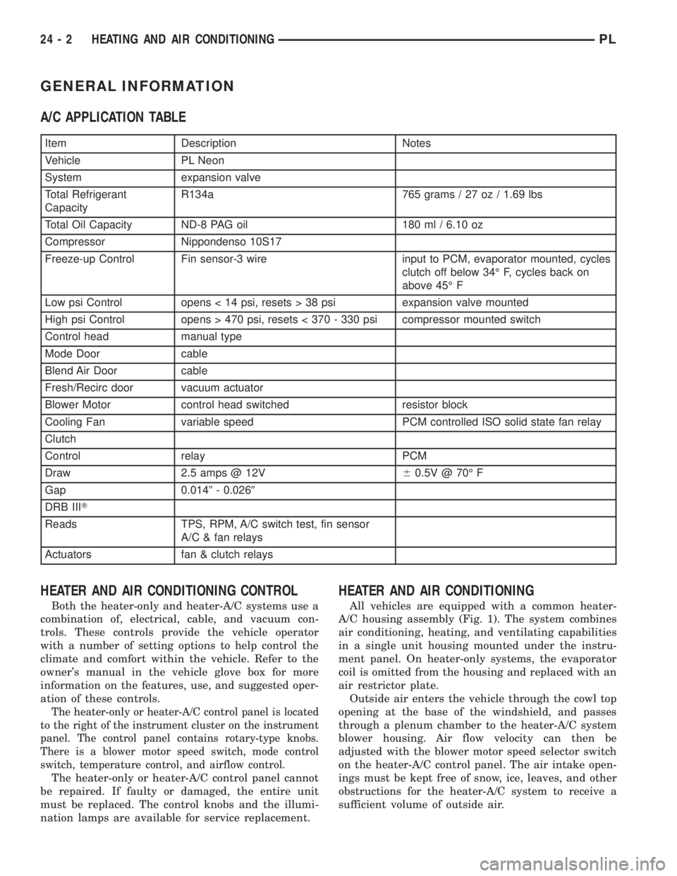
A/C APPLICATION TABLE
Item Description Notes
Vehicle PL Neon
System expansion valve
Total Refrigerant
CapacityR134a 765 grams / 27 oz / 1.69 lbs
Total Oil Capacity ND-8 PAG oil 180 ml / 6.10 oz
Compressor Nippondenso 10S17
Freeze-up Control Fin sensor-3 wire input to PCM, evaporator mounted, cycles
clutch off below 34É F, cycles back on
above 45É F
Low psi Control opens < 14 psi, resets > 38 psi expansion valve mounted
High psi Control opens > 470 psi, resets < 370 - 330 psi compressor mounted switch
Control head manual type
Mode Door cable
Blend Air Door cable
Fresh/Recirc door vacuum actuator
Blower Motor control head switched resistor block
Cooling Fan variable speed PCM controlled ISO solid state fan relay
Clutch
Control relay PCM
Draw 2.5 amps @ 12V60.5V @ 70É F
Gap 0.014º - 0.0269
DRB IIIT
Reads TPS, RPM, A/C switch test, fin sensor
A/C & fan relays
Actuators fan & clutch relays
HEATER AND AIR CONDITIONING CONTROL
Both the heater-only and heater-A/C systems use a
combination of, electrical, cable, and vacuum con-
trols. These controls provide the vehicle operator
with a number of setting options to help control the
climate and comfort within the vehicle. Refer to the
owner's manual in the vehicle glove box for more
information on the features, use, and suggested oper-
ation of these controls.
The heater-only or heater-A/C control panel is located
to the right of the instrument cluster on the instrument
panel. The control panel contains rotary-type knobs.
There is a blower motor speed switch, mode control
switch, temperature control, and airflow control.
The heater-only or heater-A/C control panel cannot
be repaired. If faulty or damaged, the entire unit
must be replaced. The control knobs and the illumi-
nation lamps are available for service replacement.
HEATER AND AIR CONDITIONING
All vehicles are equipped with a common heater-
A/C housing assembly (Fig. 1). The system combines
air conditioning, heating, and ventilating capabilities
in a single unit housing mounted under the instru-
ment panel. On heater-only systems, the evaporator
coil is omitted from the housing and replaced with an
air restrictor plate.
Outside air enters the vehicle through the cowl top
opening at the base of the windshield, and passes
through a plenum chamber to the heater-A/C system
blower housing. Air flow velocity can then be
adjusted with the blower motor speed selector switch
on the heater-A/C control panel. The air intake open-
ings must be kept free of snow, ice, leaves, and other
obstructions for the heater-A/C system to receive a
sufficient volume of outside air.
24 - 2 HEATING AND AIR CONDITIONINGPL
Page 1238 of 1285

SIDE WINDOW DEMISTERS
The demisters direct air from the unit housing
through the outlets located on the top corners of the
instrument panel. The demisters operate when the
mode selector is anywhere between floor and defrost
settings. Some air may be noticeable from the demis-
ter outlets when the mode selector is in the bilevel to
floor positions.
SYSTEM AIRFLOW
The system pulls outside (ambient) air through the
cowl opening at the base of the windshield. Then it
goes into the plenum chamber above the unit hous-
ing. On air conditioned vehicles, the air passes
through the evaporator. Air flow can be directed
either through or around the heater core. This is
done by adjusting the blend-air door with the TEMP
control on the instrument panel. The air flow can
then be directed from the panel, floor and defrost
outlets in various combinations using the mode selec-
tor. There are 17 different mode selections possible.
Air flow velocity can be adjusted with the blower
speed selector switch on the instrument panel.
On A/C equipped vehicles the ambient air intake
can be controlled by opening and closing the recircu-
lating air door. When placed in RECIRC, air that is
inside vehicle is removed continuously and recircu-
lated through unit housing. Ambient air cannot be
controlled on vehicles without A/C. The system uses
outside air at all times.
The air conditioning compressor can be engaged by
turning the fan switch counterclockwise from the off
position. It can also be engaged by placing the mode
control in the mix to defrost positions. This will
remove heat and humidity from the air before it is
directed through or around the heater core.
SYSTEM OIL LEVEL
It is important to have the correct amount of oil in
the A/C system to ensure proper lubrication of the
compressor. Too little oil will result in damage to the
compressor. Too much oil will reduce the cooling
capacity of the system and consequently result in
higher discharge air temperatures.
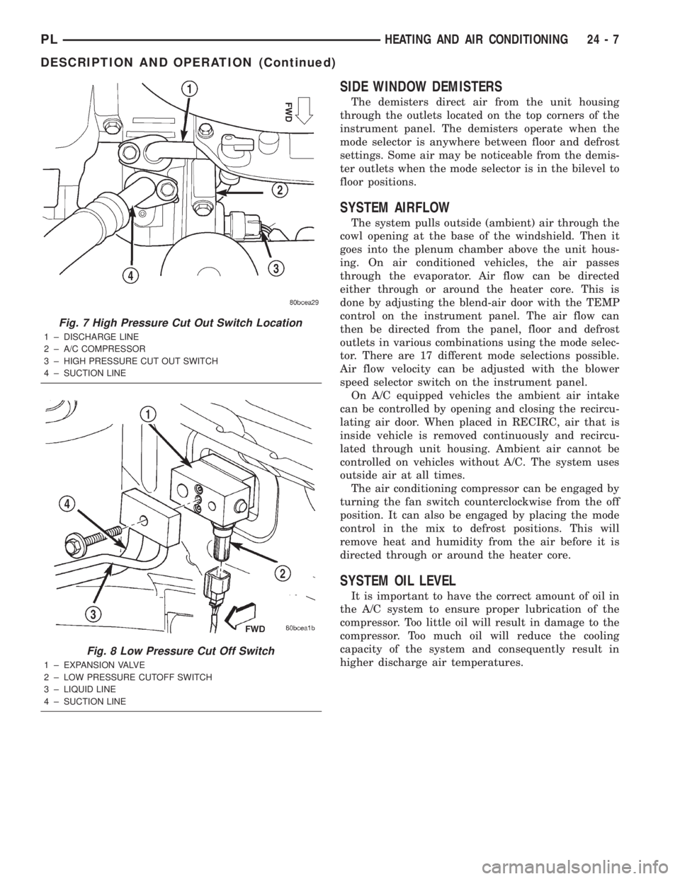
Fig. 7 High Pressure Cut Out Switch Location
1 ± DISCHARGE LINE
2 ± A/C COMPRESSOR
3 ± HIGH PRESSURE CUT OUT SWITCH
4 ± SUCTION LINE
Fig. 8 Low Pressure Cut Off Switch
1 ± EXPANSION VALVE
2 ± LOW PRESSURE CUTOFF SWITCH
3 ± LIQUID LINE
4 ± SUCTION LINE
PLHEATING AND AIR CONDITIONING 24 - 7
DESCRIPTION AND OPERATION (Continued)