Page 5 of 4592
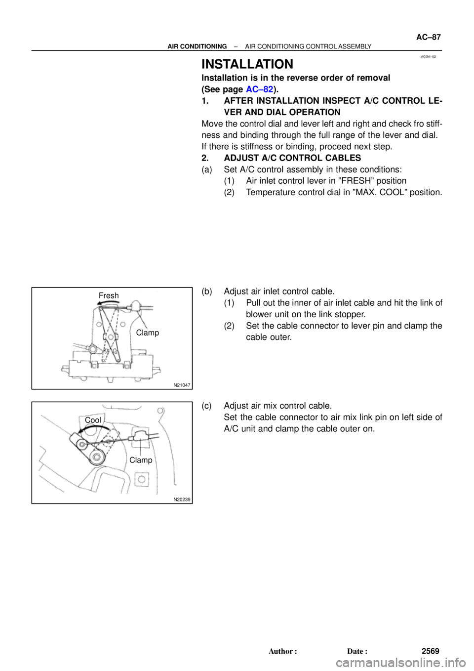
I01387
Condition : Periodically cools and then fails to cool
I01388
Condition: Insufficient cooling
± AIR CONDITIONINGAIR CONDITIONING SYSTEM
AC±5
2487 Author�: Date�:
(2) Moisture present in refrigeration system.
Symptom seen in
refrigeration systemProbable causeDiagnosisRemedy
During operation, pressure on low
pressure side sometimes become
a vacuum and sometime normal
Moisture entered in refrigeration
system freezes at expansion valve
orifice and temporarily stops cycle,
but normal state is restored after a
time when the ice melts� Drier oversaturated state
� Moisture in refrigeration system
freezes at expansion valve orifice
and blocks circulation of refriger-
ant(1) Replace receiver
(2) Remove moisture in cycle
through repeatedly evacuating air
(3) Charge proper amount of new
refrigerant
(3) Insufficient cooling
Symptom seen in
refrigeration systemProbable causeDiagnosisRemedy
� Pressure low on both low and
high pressure sides
� Bubbles seen in sight glass con-
tinuously
� Insufficient cooling performance
Gas leakage at some place in re-
frigeration system� Insufficient refrigerant in system
� Refrigerant leaking
(1) Check for gas leakage with gas
leak detector and repair if neces-
sary
(2) Charge proper amount of re-
frigerant
(3) If indicated pressure value is
near 0 when connected to gauge,
create the vacuum after inspecting
and repairing the location of the
leak
Page 9 of 4592

± AIR CONDITIONINGAIR CONDITIONING SYSTEM
AC±9
2491 Author�: Date�:
3. INSPECT IDLE±UP SPEED
(a) Warm up engine.
(b) Inspect idle±up speed when the these conditions are es-
tablished.
�Warm up engine
�Blower speed control switch at ºHIº position
�A/C switch ON
�Temperature control dial at ºCOOLº position
Magnetic clutch conditionIdle±up speed
Magnetic clutch not engaged700 ± 50 rpm
Magnetic clutch engaged700 ± 50 rpm
If idle speed is not as specified, check ISC valve and air intake
system.
4. INSPECT FOR LEAKAGE OF REFRIGERANT
(a) Perform in these conditions:
�Stop engine.
�Secure good ventilation (If not the gas leak detector
may react to volatile gases witch are not refrigerant,
such as evaporated gasoline and exhaust gas.)
�Repeat the test 2 or 3 times.
�Make sure that there is some refrigerant remaining
in the refrigeration system.
When compressor is OFF: approx. 392 ± 588 kPa
(4 ± 6 kgf/ cm
2, 57 ± 85 psi)
(b) Bring the gas leak detector close to the drain hose before
performing the test.
HINT:
�After the blower motor stopped, leave the cooling unit for
more than 15 minutes.
�Expose the gas leak detector sensor the under the drain
hose.
�When bring the gas leak detector close to the drain hose,
make sure that the gas leak detector does not react to the
volatile gases.
If such reaction is unavoidable, the vehicle must be lifted up.
(c) If gas leak is not detected on the drain hose, remove the
blower resistor from the cooling unit. Then insert the gas
leak detector sensor into the unit and perform the test.
(d) Disconnect the connector and leave the pressure switch
for approx. 20 minutes. Then bring the gas leak detector
close to the pressure switch and perform the test.
(e) Bring the gas leak detector close to the refrigerant lines
and perform the test.
Page 10 of 4592
AC0LJ±03
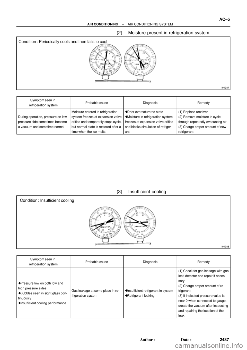
N13795
Quick Disconnect
Adapter
Charging
Service ValveHose
N13794
Vacuum Pump
Vacuum Pump Adapter
N13791
Low Pressure
Service Valve
Vacuum Pump Adapter High Pressure
Service ValveManifold
Gauge
Set
AC±10
± AIR CONDITIONINGAIR CONDITIONING SYSTEM
2492 Author�: Date�:
EVACUATING
1. CONNECT QUICK DISCONNECT ADAPTER TO
CHARGING HOSES
2. REMOVE CAPS FROM SERVICE VALVES ON RE-
FRIGERANT LINES
3. SET ON MANIFOLD GAUGE SET
(a) Close both hand valves of manifold gauge set.
(b) Connect the quick disconnect adapters to the service
valves.
4. EVACUATE AIR FROM REFRIGERATION SYSTEM
(a) Connect the vacuum pump adapter to the vacuum pump.
(b) Connect the center hose of the manifold gauge set to the
vacuum pump adapter.
(c) Open both the high and low hand valves and run the vacu-
um pump.
(d) After 10 minutes or more, check that the low pressure
gauge indicates 750 mmHg (30 in. Hg) or more.
HINT:
If the reading 750 mmHg (30 in. Hg) or more, close both hand
valves of manifold gauge set and stop the vacuum pump.
Check the system for leaks and repair necessary.
(e) Close both the high and low hand valves and stop the vac-
uum pump.
(f) Leave the system in this condition for 5 minutes or more
and check that there is no gauge indicator.
Page 42 of 4592
AC0M6±02
N20277
P19978
± AIR CONDITIONINGCOMPRESSOR AND MAGNETIC CLUTCH
AC±41
2523 Author�: Date�:
REMOVAL
1. RUN ENGINE AT IDLE SPEED WITH A/C ON FOR
APPROX.10 MINUTES
2. STOP ENGINE
3. DISCONNECT NEGATIVE (±) TERMINAL CABLE
FROM BATTERY
4. DISCHARGE REFRIGERANT FROM REFRIGERATION
SYSTEM
5. REMOVE DRIVE BELT
(See page AC±17)
6. 1MZ±FE engine models:
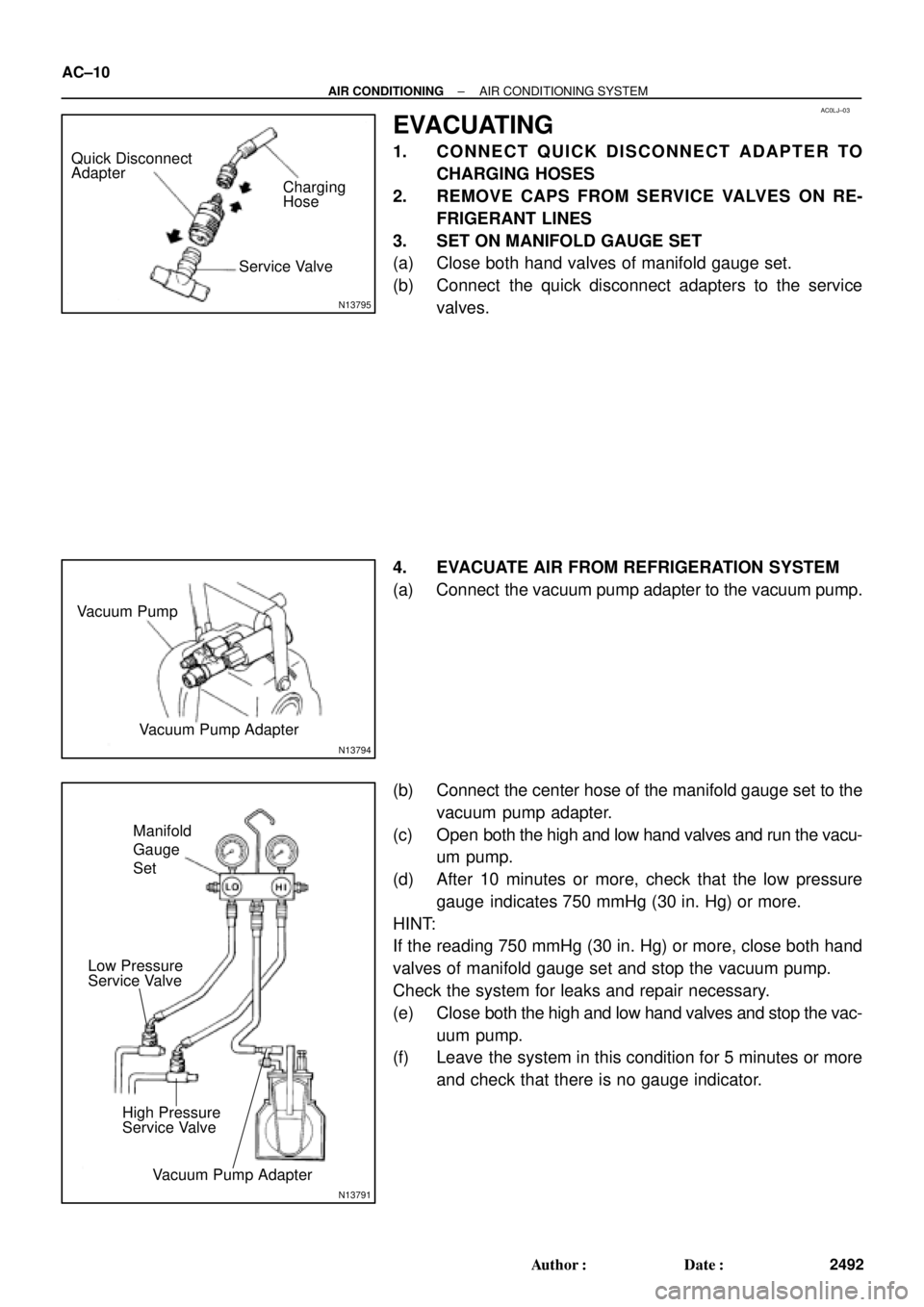
REMOVE SUCTION HOSE
(a) Remove the suction hose clamping bolt.
(b) Disconnect the wire harness clamp.
(c) Loosen the nut and bolts and remove the suction hose.
NOTICE:
Cap the open fittings immediately to keep moisture or dirt
out of the system.
7. 1MZ±FE engine models:
DISCONNECT DISCHARGE HOSE
Remove the bolt and disconnect the hose.
NOTICE:
Cap the open fittings immediately to keep moisture or dirt
out of the system.
8. 1MZ±FE engine models:
REMOVE GENERATOR
(a) Disconnect the generator connector.
(b) Remove the nut, and disconnect the generator wire.
(c) Disconnect the wire harness from the clip.
(d) Remove the pivot bolt, plate washer, adjusting lock bolt
and generator.
Page 68 of 4592
N20291
AC0N2±02
Z13470
Magnetic clutch control
Low pressure side
ON (Continuity)
196 kPa
(2.0 kgf/cm
2, 28 psi)High pressure side
3, 140 kPa
(32.0kgf/cm2, 455 psi)
OFF (No Continuity)
Z13471
1, 226 kPa
(12.5 kgf/cm2, 178 psi)OFF
(No Continuity) Condenser fan control
ON
(Continuity)150 kPa
(15.5 kgf/cm
2, 220 psi)
± AIR CONDITIONINGPRESSURE SWITCH
AC±67
2549 Author�: Date�:
PRESSURE SWITCH
ON±VEHICLE INSPECTION
1. SET ON MANIFOLD GAUGE SET
(See page AC±19)
2. DISCONNECT CONNECTOR FROM PRESSURE
SWITCH
3. RUN ENGINE AT APPROX. 1,500 RPM
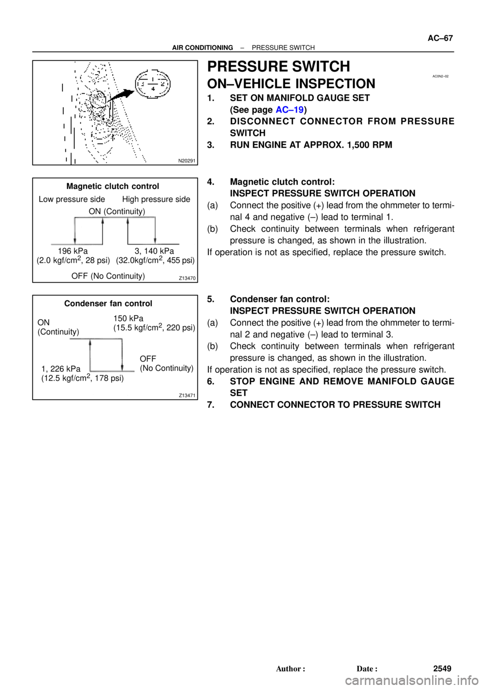
4. Magnetic clutch control:
INSPECT PRESSURE SWITCH OPERATION
(a) Connect the positive (+) lead from the ohmmeter to termi-
nal 4 and negative (±) lead to terminal 1.
(b) Check continuity between terminals when refrigerant
pressure is changed, as shown in the illustration.
If operation is not as specified, replace the pressure switch.
5. Condenser fan control:
INSPECT PRESSURE SWITCH OPERATION
(a) Connect the positive (+) lead from the ohmmeter to termi-
nal 2 and negative (±) lead to terminal 3.
(b) Check continuity between terminals when refrigerant
pressure is changed, as shown in the illustration.
If operation is not as specified, replace the pressure switch.
6. STOP ENGINE AND REMOVE MANIFOLD GAUGE
SET
7. CONNECT CONNECTOR TO PRESSURE SWITCH
Page 88 of 4592
AC0NI±02
N21047
Fresh
Clamp
N20239
Clamp Cool
± AIR CONDITIONINGAIR CONDITIONING CONTROL ASSEMBLY
AC±87
2569 Author�: Date�:
INSTALLATION
Installation is in the reverse order of removal
(See page AC±82).
1. AFTER INSTALLATION INSPECT A/C CONTROL LE-
VER AND DIAL OPERATION
Move the control dial and lever left and right and check fro stiff-
ness and binding through the full range of the lever and dial.
If there is stiffness or binding, proceed next step.
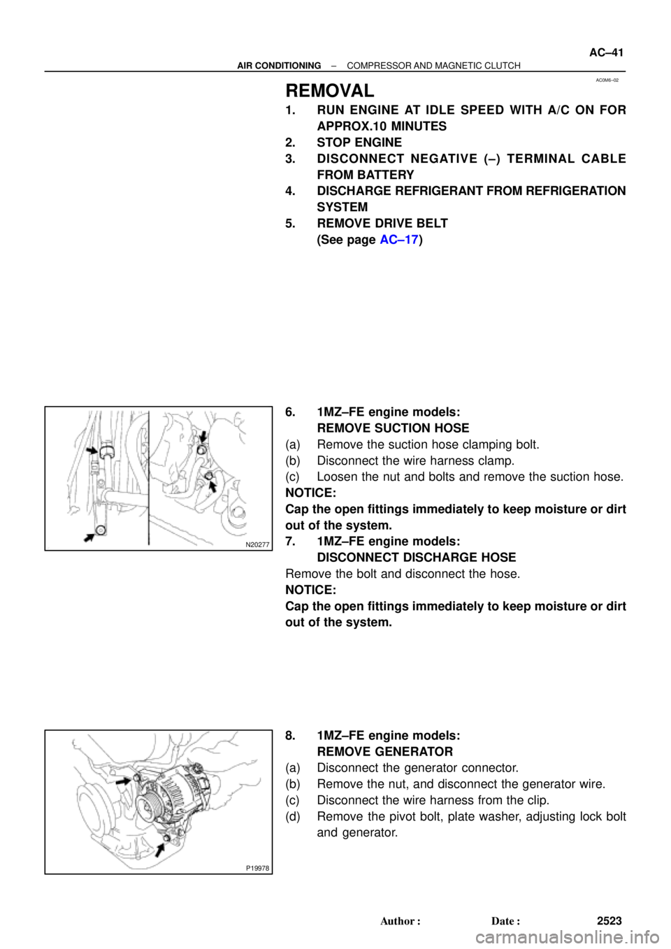
2. ADJUST A/C CONTROL CABLES
(a) Set A/C control assembly in these conditions:
(1) Air inlet control lever in ºFRESHº position
(2) Temperature control dial in ºMAX. COOLº position.
(b) Adjust air inlet control cable.
(1) Pull out the inner of air inlet cable and hit the link of
blower unit on the link stopper.
(2) Set the cable connector to lever pin and clamp the
cable outer.
(c) Adjust air mix control cable.
Set the cable connector to air mix link pin on left side of
A/C unit and clamp the cable outer on.
Page 103 of 4592
AX039±01
Q10052
Q10339
0.8 ± 1.5 mm(0.031 ± 0.059 in.)200 mm
(7.87 in.)
± AUTOMATIC TRANSAXLE (A140E)THROTTLE CABLE
AX±9
1902 Author�: Date�:
THROTTLE CABLE
ON±VEHICLE REPAIR
1. DISCONNECT THROTTLE CABLE
(a) Disconnect the cable from the throttle linkage.
(b) Disconnect the cable from the cable clamps in the engine
compartment.
2. REMOVE PARK/NEUTRAL POSITION SWITCH
(See page AX±4)
3. REMOVE VALVE BODY (See page AX±5)
4. REMOVE THROTTLE CABLE
(a) Remove the retaining bolt and plate.
(b) Pull out the cable from the transaxle case.
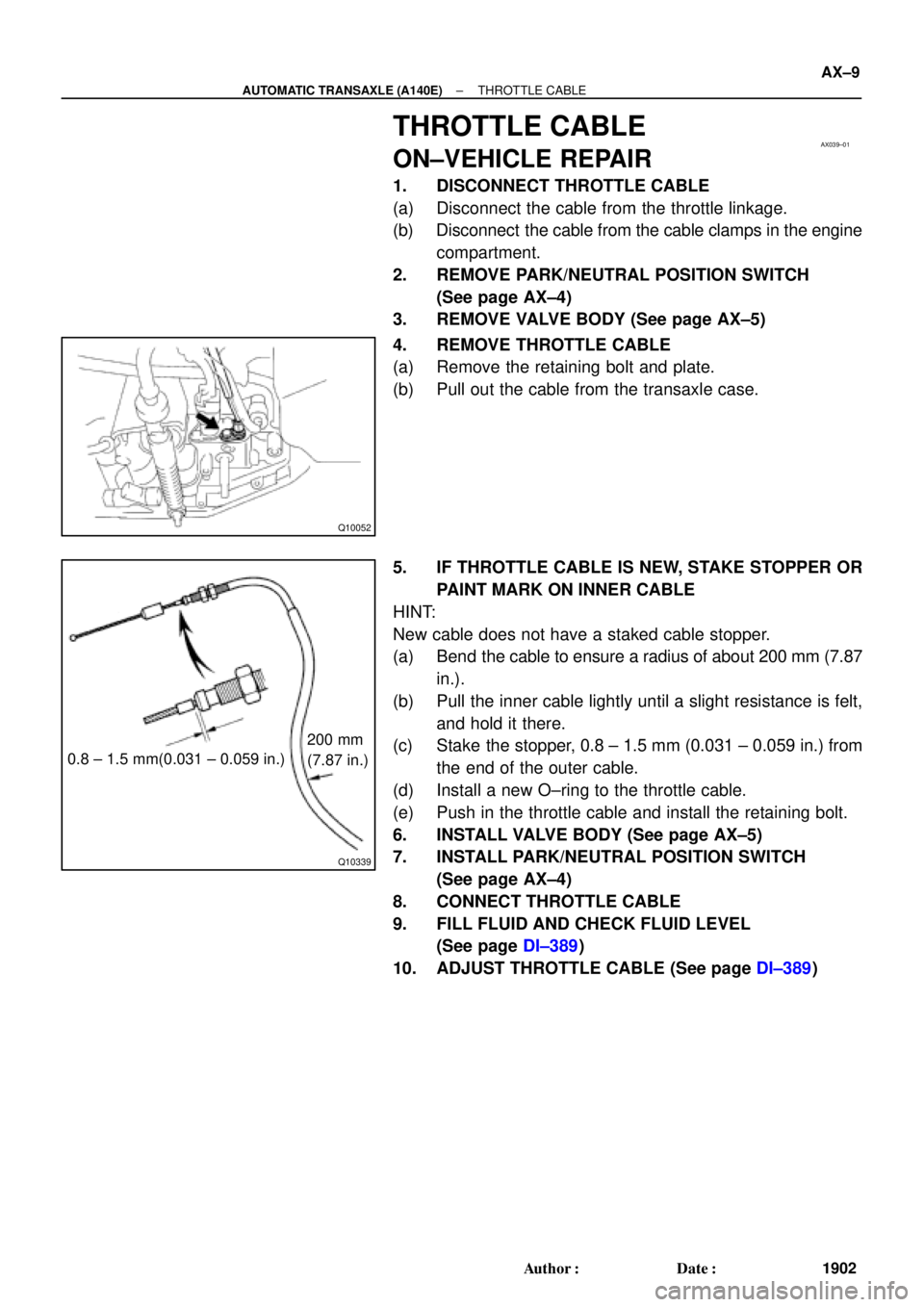
5. IF THROTTLE CABLE IS NEW, STAKE STOPPER OR
PAINT MARK ON INNER CABLE
HINT:
New cable does not have a staked cable stopper.
(a) Bend the cable to ensure a radius of about 200 mm (7.87
in.).
(b) Pull the inner cable lightly until a slight resistance is felt,
and hold it there.
(c) Stake the stopper, 0.8 ± 1.5 mm (0.031 ± 0.059 in.) from
the end of the outer cable.
(d) Install a new O±ring to the throttle cable.
(e) Push in the throttle cable and install the retaining bolt.
6. INSTALL VALVE BODY (See page AX±5)
7. INSTALL PARK/NEUTRAL POSITION SWITCH
(See page AX±4)
8. CONNECT THROTTLE CABLE
9. FILL FLUID AND CHECK FLUID LEVEL
(See page DI±389)
10. ADJUST THROTTLE CABLE (See page DI±389)
Page 106 of 4592
AX03C±01
D00760
Shift Lock Override Cover
Shift Lock Override Button
Stop Light Switch
Key Interlock Solenoid
Shift Lock
Control Unit Assembly AX±12
± AUTOMATIC TRANSAXLE (A140E)SHIFT LOCK SYSTEM (TMC Made)
1905 Author�: Date�:
SHIFT LOCK SYSTEM (TMC Made)
LOCATION