Page 129 of 4592
D01020
D01021
D01059
D01058
D01023
AX±8
± AUTOMATIC TRANSAXLE (A541E)VALVE BODY ASSEMBLY
1928 Author�: Date�:
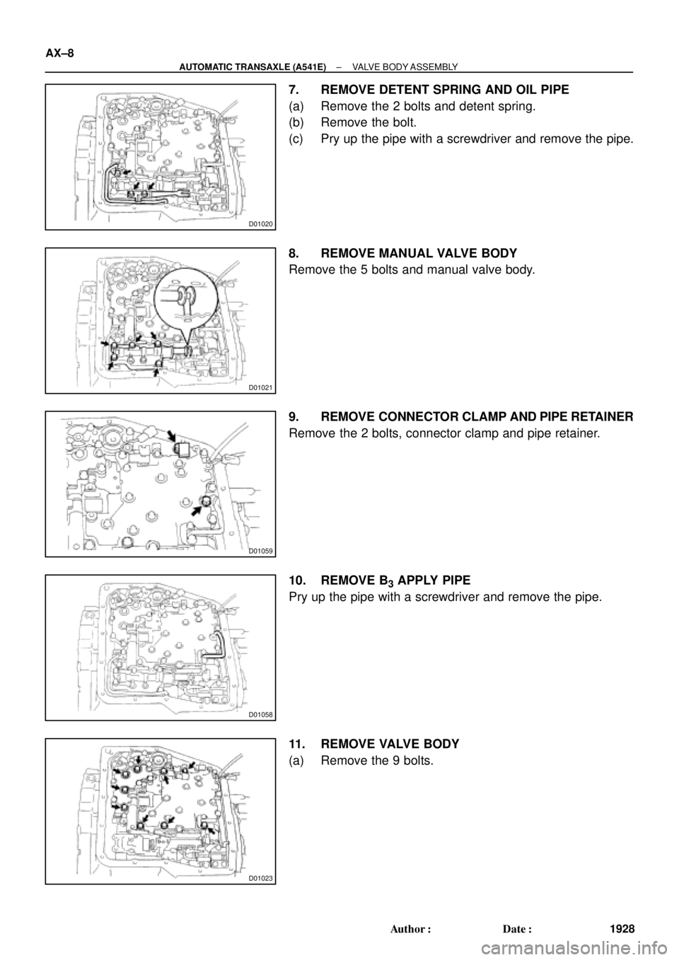
7. REMOVE DETENT SPRING AND OIL PIPE
(a) Remove the 2 bolts and detent spring.
(b) Remove the bolt.
(c) Pry up the pipe with a screwdriver and remove the pipe.
8. REMOVE MANUAL VALVE BODY
Remove the 5 bolts and manual valve body.
9. REMOVE CONNECTOR CLAMP AND PIPE RETAINER
Remove the 2 bolts, connector clamp and pipe retainer.
10. REMOVE B
3 APPLY PIPE
Pry up the pipe with a screwdriver and remove the pipe.
11. REMOVE VALVE BODY
(a) Remove the 9 bolts.
Page 1094 of 4592
P10827
SST (C)
SST (A)
Turn
P13598SST (B)
SST (A) Turn
S05070
P13490
SST CH±8
± CHARGING (5S±FE)GENERATOR
1755 Author�: Date�:
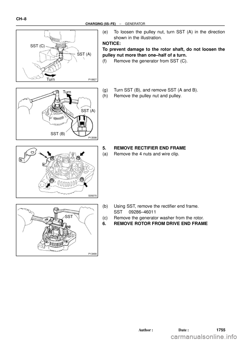
(e) To loosen the pulley nut, turn SST (A) in the direction
shown in the illustration.
NOTICE:
To prevent damage to the rotor shaft, do not loosen the
pulley nut more than one±half of a turn.
(f) Remove the generator from SST (C).
(g) Turn SST (B), and remove SST (A and B).
(h) Remove the pulley nut and pulley.
5. REMOVE RECTIFIER END FRAME
(a) Remove the 4 nuts and wire clip.
(b) Using SST, remove the rectifier end frame.
SST 09286±46011
(c) Remove the generator washer from the rotor.
6. REMOVE ROTOR FROM DRIVE END FRAME
Page 1098 of 4592
N00578
SST
P00074
SST
CH±12
± CHARGING (5S±FE)GENERATOR
1759 Author�: Date�:
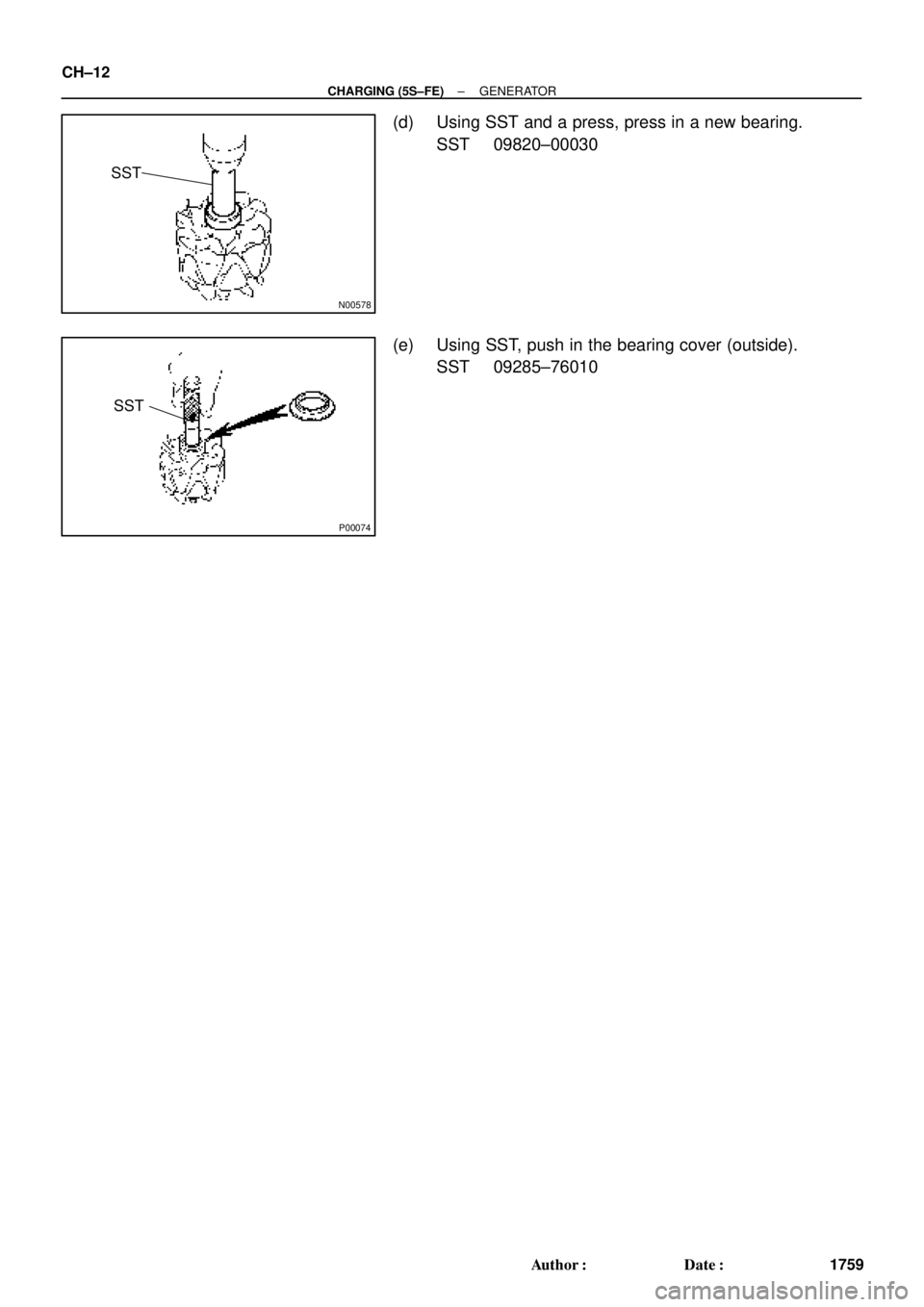
(d) Using SST and a press, press in a new bearing.
SST 09820±00030
(e) Using SST, push in the bearing cover (outside).
SST 09285±76010
Page 1110 of 4592
P10827
SST (C)
SST (A)
Turn
P10836
Turn
SST (A)
SST (B)
S05073
P01762
SST CH±8
± CHARGING (1MZ±FE)GENERATOR
1771 Author�: Date�:
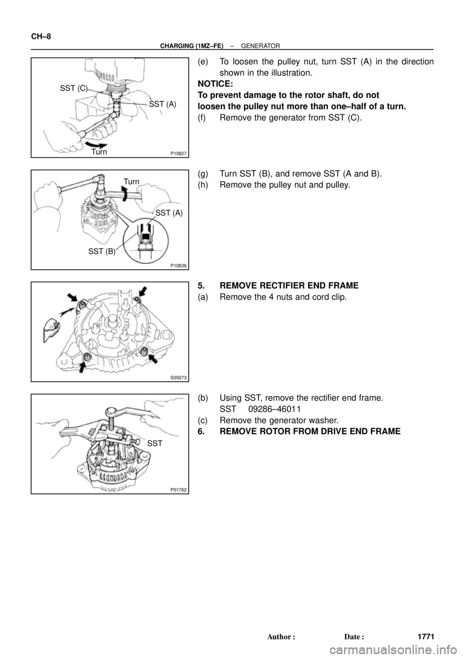
(e) To loosen the pulley nut, turn SST (A) in the direction
shown in the illustration.
NOTICE:
To prevent damage to the rotor shaft, do not
loosen the pulley nut more than one±half of a turn.
(f) Remove the generator from SST (C).
(g) Turn SST (B), and remove SST (A and B).
(h) Remove the pulley nut and pulley.
5. REMOVE RECTIFIER END FRAME
(a) Remove the 4 nuts and cord clip.
(b) Using SST, remove the rectifier end frame.
SST 09286±46011
(c) Remove the generator washer.
6. REMOVE ROTOR FROM DRIVE END FRAME
Page 1114 of 4592
N00578
SST
P00074
SST
CH±12
± CHARGING (1MZ±FE)GENERATOR
1775 Author�: Date�:
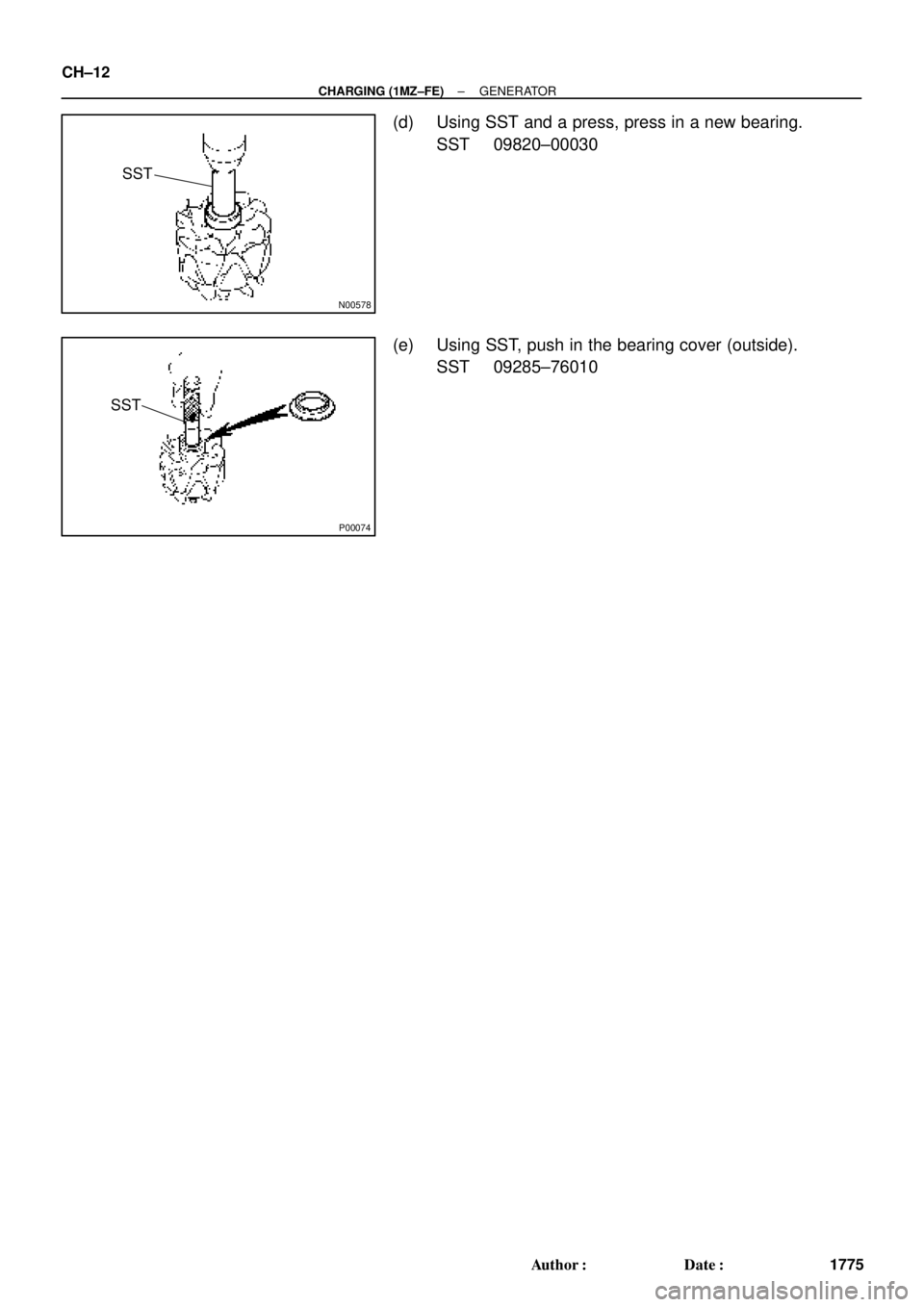
(d) Using SST and a press, press in a new bearing.
SST 09820±00030
(e) Using SST, push in the bearing cover (outside).
SST 09285±76010
Page 1148 of 4592
CO06B±03
N00918
S06015
Connect
Z19283
1
3
2
S05924
S05599
CO±8
± COOLING (5S±FE)WATER PUMP
1582 Author�: Date�:
INSTALLATION
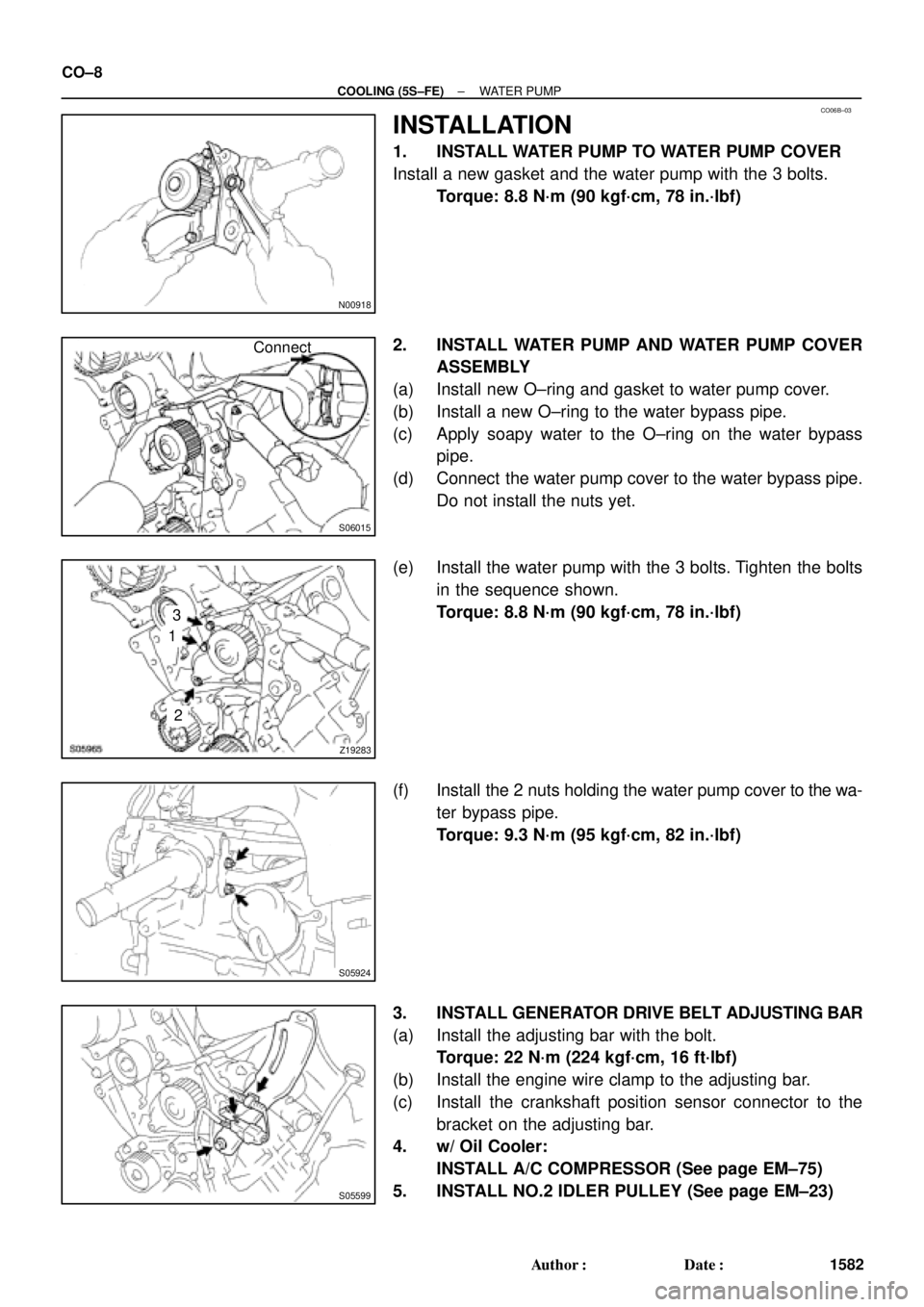
1. INSTALL WATER PUMP TO WATER PUMP COVER
Install a new gasket and the water pump with the 3 bolts.
Torque: 8.8 N´m (90 kgf´cm, 78 in.´lbf)
2. INSTALL WATER PUMP AND WATER PUMP COVER
ASSEMBLY
(a) Install new O±ring and gasket to water pump cover.
(b) Install a new O±ring to the water bypass pipe.
(c) Apply soapy water to the O±ring on the water bypass
pipe.
(d) Connect the water pump cover to the water bypass pipe.
Do not install the nuts yet.
(e) Install the water pump with the 3 bolts. Tighten the bolts
in the sequence shown.
Torque: 8.8 N´m (90 kgf´cm, 78 in.´lbf)
(f) Install the 2 nuts holding the water pump cover to the wa-
ter bypass pipe.
Torque: 9.3 N´m (95 kgf´cm, 82 in.´lbf)
3. INSTALL GENERATOR DRIVE BELT ADJUSTING BAR
(a) Install the adjusting bar with the bolt.
Torque: 22 N´m (224 kgf´cm, 16 ft´lbf)
(b) Install the engine wire clamp to the adjusting bar.
(c) Install the crankshaft position sensor connector to the
bracket on the adjusting bar.
4. w/ Oil Cooler:
INSTALL A/C COMPRESSOR (See page EM±75)
5. INSTALL NO.2 IDLER PULLEY (See page EM±23)
Page 1164 of 4592
S05959
CO06N±03
S05953
ECT Switch
Connector
Z19282
No.1
No.2Battery
Ammeter (±)
(+) (+)
(±)
Battery Ammeter CO±24
± COOLING (5S±FE)ELECTRIC COOLING FAN
1598 Author�: Date�:
ELECTRIC COOLING FAN
ON±VEHICLE INSPECTION
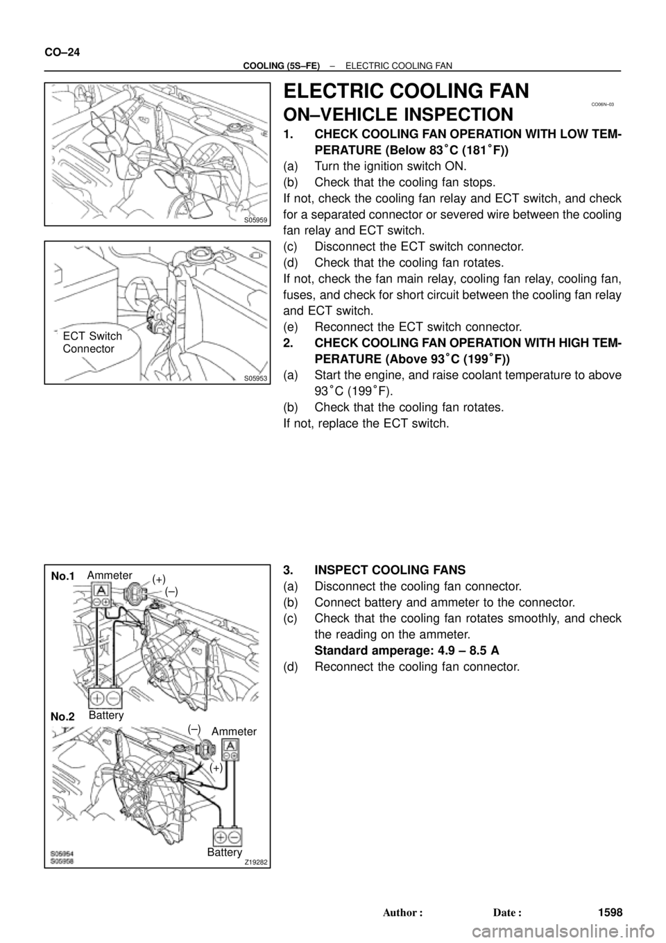
1. CHECK COOLING FAN OPERATION WITH LOW TEM-
PERATURE (Below 83°C (181°F))
(a) Turn the ignition switch ON.
(b) Check that the cooling fan stops.
If not, check the cooling fan relay and ECT switch, and check
for a separated connector or severed wire between the cooling
fan relay and ECT switch.
(c) Disconnect the ECT switch connector.
(d) Check that the cooling fan rotates.
If not, check the fan main relay, cooling fan relay, cooling fan,
fuses, and check for short circuit between the cooling fan relay
and ECT switch.
(e) Reconnect the ECT switch connector.
2. CHECK COOLING FAN OPERATION WITH HIGH TEM-
PERATURE (Above 93°C (199°F))
(a) Start the engine, and raise coolant temperature to above
93°C (199°F).
(b) Check that the cooling fan rotates.
If not, replace the ECT switch.
3. INSPECT COOLING FANS
(a) Disconnect the cooling fan connector.
(b) Connect battery and ammeter to the connector.
(c) Check that the cooling fan rotates smoothly, and check
the reading on the ammeter.
Standard amperage: 4.9 ± 8.5 A
(d) Reconnect the cooling fan connector.
Page 1232 of 4592
DI±20
± DIAGNOSTICSENGINE (5S±FE)
255 Author�: Date�:
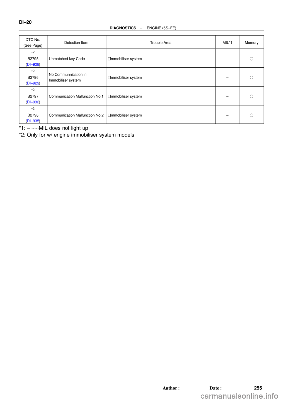
DTC No.
(See Page)Detection ItemTrouble AreaMIL*1Memory
*2
B2795
(DI±928)Unmatched key Code�Immobiliser system±�
*2
B2796
(DI±929)No Communnication in
Immobiliser system�Immobiliser system±�
*2
B2797
(DI±932)Communication Malfunction No.1�Immobiliser system±�
*2
B2798
(DI±935)Communication Malfunction No.2�Immobiliser system±�
*1: ±���MIL does not light up
*2: Only for w/ engine immobiliser system models