Page 1 of 4592

AC2810
AC0LG±02
AC2811
N11084
Wrong Okey
HI LO HILO
± AIR CONDITIONINGAIR CONDITIONING SYSTEM
AC±1
2483 Author�: Date�:
AIR CONDITIONING SYSTEM
PRECAUTION
1. DO NOT HANDLE REFRIGERANT IN AN ENCLOSED
AREA OR WEAR EYE PROTECTION
2. ALWAYS WEAR EYE PROTECTION
3. BE CAREFUL NOT TO GET LIQUID REFRIGERANT IN
YOUR EYES OR ON YOUR SKIN
If liquid refrigerant gets in your eyes or on your skin.
(a) Wash the area with lots of cool water.
CAUTION:
Do not rub your eyes or skin.
(b) Apply clean petroleum jelly to the skin.
(c) Go immediately to a physician or hospital for professional
treatment.
4. NEVER HEAT CONTAINER OR EXPOSE IT TO NAKED
FLAME
5. BE CAREFUL NOT TO DROP CONTAINER AND NOT
TO APPLY PHYSICAL SHOCKS TO IT
6. DO NOT OPERATE COMPRESSOR WITHOUT
ENOUGH REFRIGERANT IN REFRIGERATION SYS-
TEM
If there is not enough refrigerant in the refrigerant system oil lu-
brication will be insufficient and compressor burnout may occur,
so that care to avoid this, necessary care should be taken.
7. DO NOT OPEN PRESSURE MANIFOLD VALVE WHILE
COMPRESSOR IS OPERATE
If the high pressure valve is opened, refrigerant flows in the re-
verse direction and could cause the charging cylinder to rup-
ture, so open and close the only low pressure valve.
8. BE CAREFUL NOT TO OVERCHARGE SYSTEM WITH
REFRIGERANT
If refrigerant is overcharged, it causes problems such as insuffi-
cient cooling, poor fuel economy, engine overheating etc.
Page 11 of 4592
AC21S±01
N13793
Charging Cylinder High Pressure
Service Valve Low Pressure
Service ValvePush
Air
N13792
Gas Leak
Detector
± AIR CONDITIONINGAIR CONDITIONING SYSTEM
AC±11
2493 Author�: Date�:
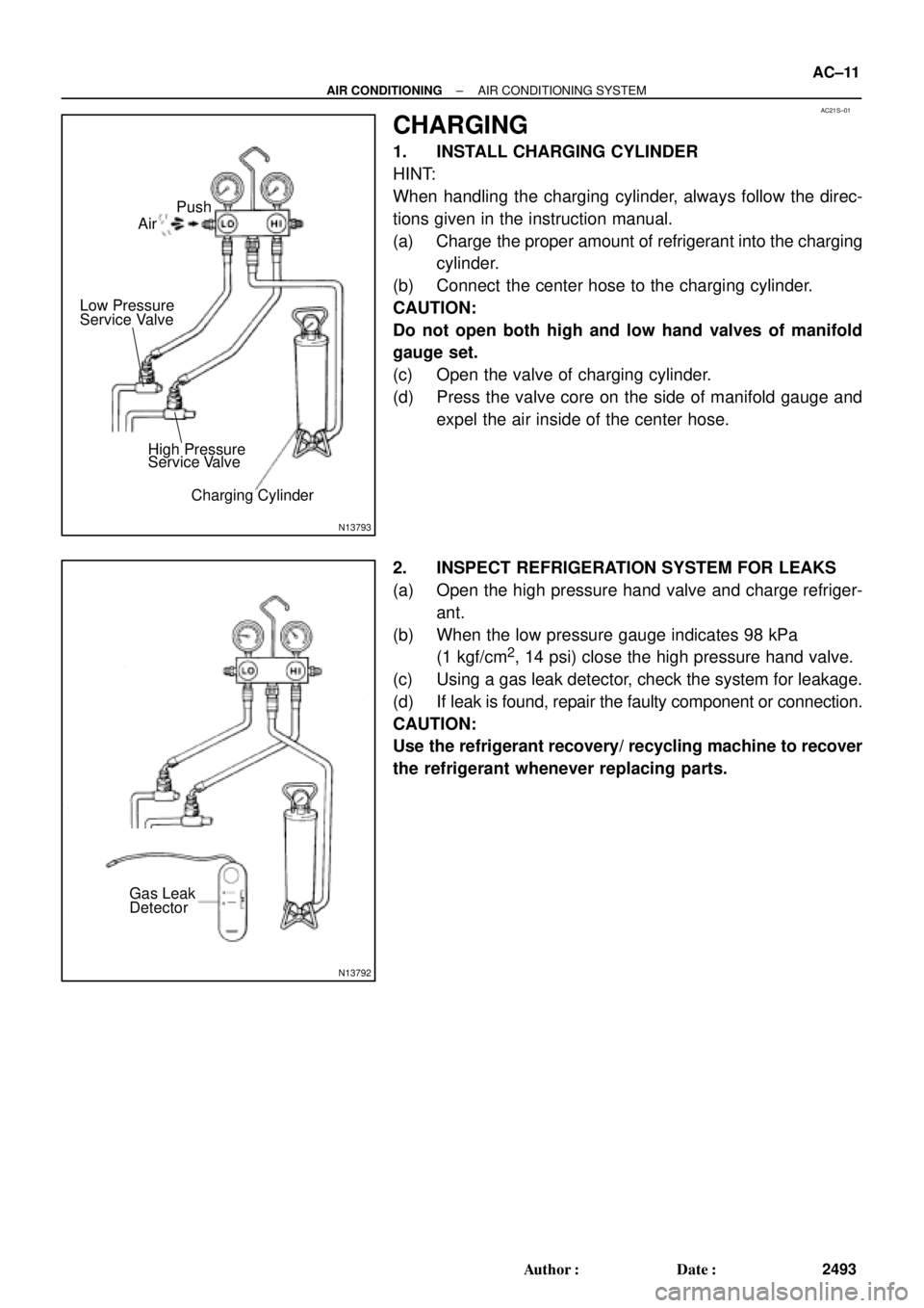
CHARGING
1. INSTALL CHARGING CYLINDER
HINT:
When handling the charging cylinder, always follow the direc-
tions given in the instruction manual.
(a) Charge the proper amount of refrigerant into the charging
cylinder.
(b) Connect the center hose to the charging cylinder.
CAUTION:
Do not open both high and low hand valves of manifold
gauge set.
(c) Open the valve of charging cylinder.
(d) Press the valve core on the side of manifold gauge and
expel the air inside of the center hose.
2. INSPECT REFRIGERATION SYSTEM FOR LEAKS
(a) Open the high pressure hand valve and charge refriger-
ant.
(b) When the low pressure gauge indicates 98 kPa
(1 kgf/cm
2, 14 psi) close the high pressure hand valve.
(c) Using a gas leak detector, check the system for leakage.
(d) If leak is found, repair the faulty component or connection.
CAUTION:
Use the refrigerant recovery/ recycling machine to recover
the refrigerant whenever replacing parts.
Page 384 of 4592
AUTOMATIC TRANSAXLEVALVE BODY ±
AX±78
2. REMOVE LOCK PLATE
3. REMOVE B
0 ACCUMULATOR ASSEMBLY
(a) Remove the 3 bolts.
(b) Remove the B
0 accumulator assembly.
4. DISASSEMBLE B
0 ACCUMULATOR ASSEMBLY
(a) Applying compressed air to the cylinder hole, remove the
piston and spring.
(b) Remove the 2 O±rings from the piston.
5. REMOVE NO.4 SOLENOID
(a) Remove the No.4 solenoid.
(b) Remove the O±ring from the solenoid.
6. REMOVE NO.1 LOWER VALVE BODY COVER
Remove the 5 bolts and No.1 lower valve body cover.
Page 390 of 4592
AUTOMATIC TRANSAXLEVALVE BODY ±
AX±84
10. INSTALL LOWER VALVE BODY COVER GASKETS
AND NO.2 PLATE
Position a new gasket and plate and then another new
gasket.
HINT: Both gaskets are identical.
11. INSTALL LOWER VALVE BODY COVER
(a) Position the lower valve body cover.
(b) Install and finger tighten the 5 bolts.
HINT: Each bolt length is indicated below.
Bolt length
Bolt A: 47 mm (1.850 in.)
Bolt B: 14 mm (0.551 in.)
12. INSTALL PRESSURE RELIEF VALVE
13. TIGHTEN BOLTS OF UPPER AND LOWER VALVE BO-
DIES
(a) Tighten the 16 bolts in the lower valve body.
Torque: 6.6 N´m (67 kgf´cm, 58 in.´lbf)
(b) Tighten the 3 bolts in the upper valve body.
Torque: 6.6 N´m (67 kgf´cm, 58 in.´lbf)
14. INSTALL B0 ACCUMULATOR ASSEMBLY
(a) Coat new O±rings with ATF and install them to the piston.
(b) Install the spring and piston into the cylinder.
Spring dimensions
mm (in.)
ColorFree lengthCoil outer diameter
Inner White47.5 (1.870)18.9 (0.744)
Outer None16.3 (0.642)20.7 (0.815)
Page 438 of 4592
AUTOMATIC TRANSAXLESERVICE SPECIFICATIONS ±
AX±132
TORQUE SPECIFICATIONS
Part tightenedN´mkgf´cmft´lbf
Oil cooler pipe union2727520
Oil pan4.95043 in.´lbf
Valve body x Transaxle case1111 08
Accumulator x Cover101007
Oil pump x Transaxle case2222516
O/D case x Transaxle case2525018
Differential LH side bearing retainer1919514
Differential RH retainer1919514
Differential carrier cover3940029
Oil pump body x Stator shaft101007
Ring gear x Differential case1241,26091
Upper valve body x Lower valve body6.66758 in.´lbf
Accumulator cylinder x Valve body6.66758 in.´lbf
Solenoid x Valve body6.66758 in.´lbf
Counter drive gear lock nut2802,855206
Carrire cover x Transaxle case3940029
Parking lock pawl bracket7.47565 in.´lbf
Oil strainer x Transaxle case1111 08
AX04N±03
Page 527 of 4592
AUTOMATIC TRANSAXLEVALVE BODY ±
AX±78
2. REMOVE LOCK PLATE
3. REMOVE B
0 ACCUMULATOR ASSEMBLY
(a) Remove the 3 bolts.
(b) Remove the B
0 accumulator assembly.
4. DISASSEMBLE B
0 ACCUMULATOR ASSEMBLY
(a) Applying compressed air to the cylinder hole, remove the
piston and spring.
(b) Remove the 2 O±rings from the piston.
5. REMOVE NO.4 SOLENOID
(a) Remove the No.4 solenoid.
(b) Remove the O±ring from the solenoid.
6. REMOVE NO.1 LOWER VALVE BODY COVER
Remove the 5 bolts and No.1 lower valve body cover.
Page 533 of 4592
AUTOMATIC TRANSAXLEVALVE BODY ±
AX±84
10. INSTALL LOWER VALVE BODY COVER GASKETS
AND NO.2 PLATE
Position a new gasket and plate and then another new
gasket.
HINT: Both gaskets are identical.
11. INSTALL LOWER VALVE BODY COVER
(a) Position the lower valve body cover.
(b) Install and finger tighten the 5 bolts.
HINT: Each bolt length is indicated below.
Bolt length
Bolt A: 47 mm (1.850 in.)
Bolt B: 14 mm (0.551 in.)
12. INSTALL PRESSURE RELIEF VALVE
13. TIGHTEN BOLTS OF UPPER AND LOWER VALVE BO-
DIES
(a) Tighten the 16 bolts in the lower valve body.
Torque: 6.6 N´m (67 kgf´cm, 58 in.´lbf)
(b) Tighten the 3 bolts in the upper valve body.
Torque: 6.6 N´m (67 kgf´cm, 58 in.´lbf)
14. INSTALL B0 ACCUMULATOR ASSEMBLY
(a) Coat new O±rings with ATF and install them to the piston.
(b) Install the spring and piston into the cylinder.
Spring dimensions
mm (in.)
ColorFree lengthCoil outer diameter
Inner White47.5 (1.870)18.9 (0.744)
Outer None16.3 (0.642)20.7 (0.815)
Page 581 of 4592
AUTOMATIC TRANSAXLESERVICE SPECIFICATIONS ±
AX±132
TORQUE SPECIFICATIONS
Part tightenedN´mkgf´cmft´lbf
Oil cooler pipe union2727520
Oil pan4.95043 in.´lbf
Valve body x Transaxle case1111 08
Accumulator x Cover101007
Oil pump x Transaxle case2222516
O/D case x Transaxle case2525018
Differential LH side bearing retainer1919514
Differential RH retainer1919514
Differential carrier cover3940029
Oil pump body x Stator shaft101007
Ring gear x Differential case1241,26091
Upper valve body x Lower valve body6.66758 in.´lbf
Accumulator cylinder x Valve body6.66758 in.´lbf
Solenoid x Valve body6.66758 in.´lbf
Counter drive gear lock nut2802,855206
Carrire cover x Transaxle case3940029
Parking lock pawl bracket7.47565 in.´lbf
Oil strainer x Transaxle case1111 08
AX04N±03