Page 1751 of 4592

DI03V±04
F00047
S-17-1 Iei-23-1-A
F00041
DLC2 DLC1
Tc E1
E1Tc
F00103
Normal Code
0.25 sec.
0.25 sec. 0.5 sec.
ON
OFF
ON
OFF0.5 sec. 0.5 sec.
Code 11 and 21
4 sec.1.5 sec.
2.5 sec.
Code 11 Code 21
H07517
TOYOTA
Hand±held Tester
DLC2
± DIAGNOSTICSANTI±LOCK BRAKE SYSTEM (BOSCH Made)
DI±539
774 Author�: Date�:
PRE±CHECK
1. DIAGNOSIS SYSTEM
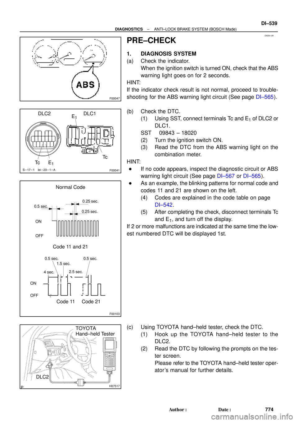
(a) Check the indicator.
When the ignition switch is turned ON, check that the ABS
warning light goes on for 2 seconds.
HINT:
If the indicator check result is not normal, proceed to trouble-
shooting for the ABS warning light circuit (See page DI±565).
(b) Check the DTC.
(1) Using SST, connect terminals Tc and E
1 of DLC2 or
DLC1.
SST 09843 ± 18020
(2) Turn the ignition switch ON.
(3) Read the DTC from the ABS warning light on the
combination meter.
HINT:
�If no code appears, inspect the diagnostic circuit or ABS
warning light circuit (See page DI±567 or DI±565).
�As an example, the blinking patterns for normal code and
codes 11 and 21 are shown on the left.
(4) Codes are explained in the code table on page
DI±542.
(5) After completing the check, disconnect terminals Tc
and E
1, and turn off the display.
If 2 or more malfunctions are indicated at the same time the low-
est numbered DTC will be displayed 1st.
(c) Using TOYOTA hand±held tester, check the DTC.
(1) Hook up the TOYOTA hand±held tester to the
DLC2.
(2) Read the DTC by following the prompts on the tes-
ter screen.
Please refer to the TOYOTA hand±held tester oper-
ator 's manual for further details.
Page 1752 of 4592

BR3890
F02201
DLC1
TsTc E1
BR3904
0.13 sec. 0.12 sec.
ON
OFF DI±540
± DIAGNOSTICSANTI±LOCK BRAKE SYSTEM (BOSCH Made)
775 Author�: Date�:
(d) Clear the DTC.
(1) Using SST, connect terminals Tc and E
1 of DLC2 or
DLC1.
SST 09843 ± 18020
(2) Turn the ignition switch ON.
(3) Clear the DTC stored in ECU by depressing the
brake pedal 8 or more times within 3 seconds.
(4) Check that the warning light shows the normal
code.
(5) Remove the SST from the terminals of DLC2 or
DLC1.
SST 09843 ± 18020
HINT:
Cancellation cannot be done by removing the battery cable or
ECU±B fuse.
2. SPEED SENSOR SIGNAL
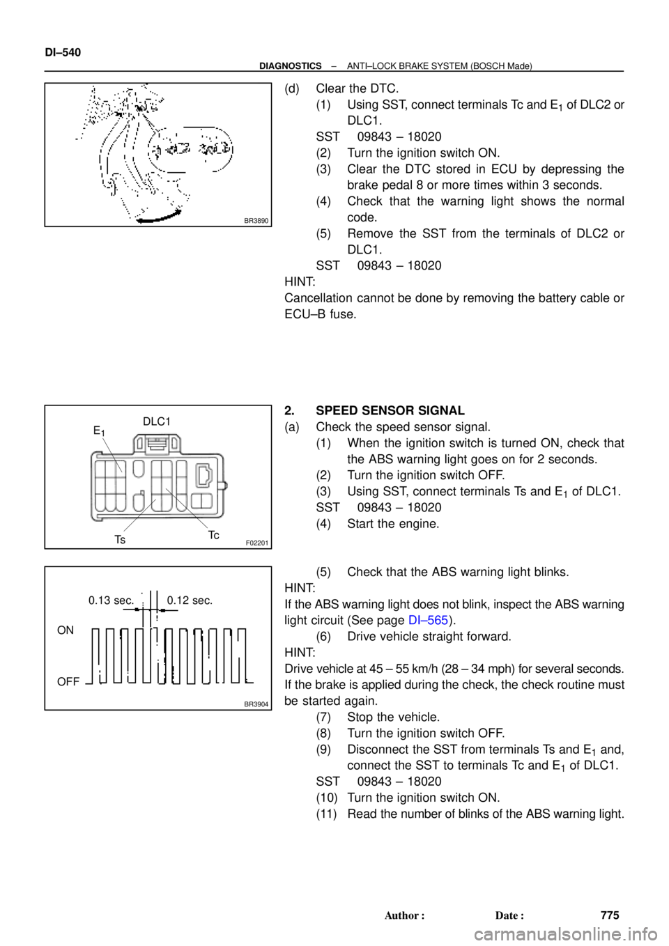
(a) Check the speed sensor signal.
(1) When the ignition switch is turned ON, check that
the ABS warning light goes on for 2 seconds.
(2) Turn the ignition switch OFF.
(3) Using SST, connect terminals Ts and E
1 of DLC1.
SST 09843 ± 18020
(4) Start the engine.
(5) Check that the ABS warning light blinks.
HINT:
If the ABS warning light does not blink, inspect the ABS warning
light circuit (See page DI±565).
(6) Drive vehicle straight forward.
HINT:
Drive vehicle at 45 ± 55 km/h (28 ± 34 mph) for several seconds.
If the brake is applied during the check, the check routine must
be started again.
(7) Stop the vehicle.
(8) Turn the ignition switch OFF.
(9) Disconnect the SST from terminals Ts and E
1 and,
connect the SST to terminals Tc and E
1 of DLC1.
SST 09843 ± 18020
(10) Turn the ignition switch ON.
(11) Read the number of blinks of the ABS warning light.
Page 1755 of 4592
DI03X±05
F01175
ABS Actuator
(w/ ECU, Relay)Front Speed Sensor
DLC1
DLC2Sensor Rotor
Rear Speed Sensor
Stop Light Switch ABS Warning Light
Sensor Rotor
Front Speed Sensor
± DIAGNOSTICSANTI±LOCK BRAKE SYSTEM (BOSCH Made)
DI±543
778 Author�: Date�:
PARTS LOCATION
Page 1756 of 4592

DI1JN±03
F00050
A6
12 345678
910 1112 13 14 15
16 17 181920 21 2223 24 2526 DI±544
± DIAGNOSTICSANTI±LOCK BRAKE SYSTEM (BOSCH Made)
779 Author�: Date�:
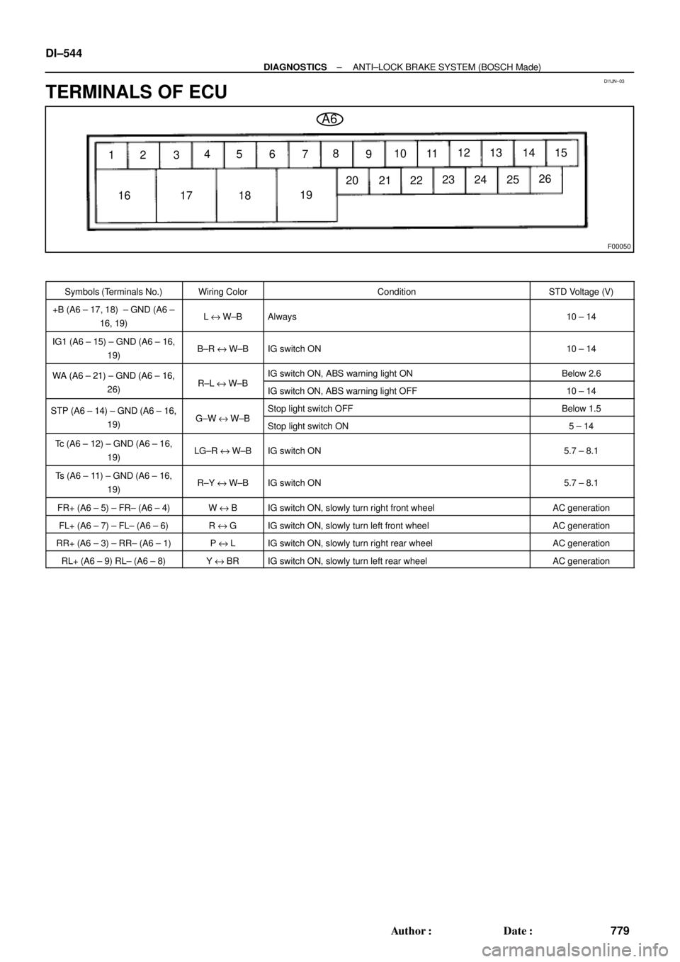
TERMINALS OF ECU
Symbols (Terminals No.)Wiring ColorConditionSTD Voltage (V)
+B (A6 ± 17, 18) ± GND (A6 ±
16, 19)L e W±BAlways10 ± 14
IG1 (A6 ± 15) ± GND (A6 ± 16,
19)B±R e W±BIG switch ON10 ± 14
WA (A6 ± 21) ± GND (A6 ± 16,RLWBIG switch ON, ABS warning light ONBelow 2.6WA (A6 21) GND (A6 16,
26)R±L e W±BIG switch ON, ABS warning light OFF10 ± 14
STP (A6 ± 14) ± GND (A6 ± 16,GWWBStop light switch OFFBelow 1.5STP (A6 14) GND (A6 16,
19)G±W e W±BStop light switch ON5 ± 14
Tc (A6 ± 12) ± GND (A6 ± 16,
19)LG±R e W±BIG switch ON5.7 ± 8.1
Ts (A6 ± 11) ± GND (A6 ± 16,
19)R±Y e W±BIG switch ON5.7 ± 8.1
FR+ (A6 ± 5) ± FR± (A6 ± 4)W e BIG switch ON, slowly turn right front wheelAC generation
FL+ (A6 ± 7) ± FL± (A6 ± 6)R e GIG switch ON, slowly turn left front wheelAC generation
RR+ (A6 ± 3) ± RR± (A6 ± 1)P e LIG switch ON, slowly turn right rear wheelAC generation
RL+ (A6 ± 9) RL± (A6 ± 8)Y e BRIG switch ON, slowly turn left rear wheelAC generation
Page 1757 of 4592

DI03Z±10
± DIAGNOSTICSANTI±LOCK BRAKE SYSTEM (BOSCH Made)
DI±545
780 Author�: Date�:
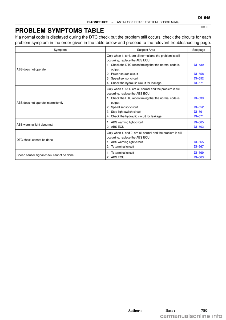
PROBLEM SYMPTOMS TABLE
If a normal code is displayed during the DTC check but the problem still occurs, check the circuits for each
problem symptom in the order given in the table below and proceed to the relevant troubleshooting page.
SymptomSuspect AreaSee page
ABS does not operate
Only when 1. to 4. are all normal and the problem is still
occurring, replace the ABS ECU.
1. Check the DTC reconfirming that the normal code is
output.
2. Power source circuit
3. Speed sensor circuit
4. Check the hydraulic circuit for leakage.
DI±539
DI±558
DI±552
DI±571
ABS does not operate intermittently
Only when 1. to 4. are all normal and the problem is still
occurring, replace the ABS ECU.
1. Check the DTC reconfirming that the normal code is
output.
2. Speed sensor circuit
3. Stop light switch circuit
4. Check the hydraulic circuit for leakage.
DI±539
DI±552
DI±561
DI±571
ABS warning light abnormal1. ABS warning light circuit
2. ABS ECUDI±565
DI±563
DTC check cannot be done
Only when 1. and 2. are all normal and the problem is still
occurring, replace the ABS ECU.
1. ABS warning light circuit
2. Tc terminal circuit
DI±565
DI±567
Speed sensor signal check cannot be done1. Ts terminal circuit
2. ABS ECUDI±569
DI±563
Page 1775 of 4592
± DIAGNOSTICSANTI±LOCK BRAKE SYSTEM (BOSCH Made)
DI±563
798 Author�: Date�:
DTC 62 ABS ECU Malfunction
CIRCUIT DESCRIPTION
DTC No.DTC Detecting ConditionTrouble Area
62ABS ECU continuously detects the proper operation of
ABS.�Battery
�ECU
Fail safe function:
If trouble occurs in the power source circuit, the ECU cuts off current to the ABS solenoid valve relay and
prohibits ABS control.
INSPECTION PROCEDURE
1 Is DTC output?
Check DTC on page DI±539.
YES Repair circuit indicated by the code output.
NO
2 Is normal code displayed?
YES Check for short circuit in harness and connec-
tor between DLC1 or DLC2 and ABS ECU
(See page IN±31).
NO
3 Does ABS warning light go off?
YES Check for open and short circuit in harness and
connector of Tc circuit between ECU and DLC2
or DLC1.
NO
DI047±06
Page 1776 of 4592
F00067
ON
IG1
(+) (±)
GND
DI±564
± DIAGNOSTICSANTI±LOCK BRAKE SYSTEM (BOSCH Made)
799 Author�: Date�:
4 Check voltage between terminals IG1 and GND of ABS actuator connector.
PREPARATION:
Disconnect ABS actuator connector.
CHECK:
(a) Turn the ignition switch ON.
(b) Measure voltage between terminals IG1 and GND of ABS
actuator harness side connector.
OK:
Voltage: 10 ± 14 V
NG Check for open and short circuit in harness and
connector between ECU±IG fuse and ABS ac-
tuator (See page IN±31).
OK
5 Check connection of ABS actuator connector.
CHECK:
Check the connection of the ABS actuator connector and check the ABS warning light goes off.
OK Repair or replace harness or connector.
NG
Check and replace ABS ECU.
Page 1777 of 4592
F00096
J/C
J4 D
ABS 7
C
R±LC10
1D
GAUGE
A6 4
DLC2ECU
Instrument
Panel J/BABS
Warning
Light
210
IG312
C10
DR±L R±L
WA 21
14 R±LJ/C
J29
C
C R±L
R±LR±L
IK3
± DIAGNOSTICSANTI±LOCK BRAKE SYSTEM (BOSCH Made)
DI±565
800 Author�: Date�:
ABS Warning Light Circuit
CIRCUIT DESCRIPTION
If the ECU detects any trouble, it lights the ABS warning light while at the same time prohibiting ABS control.
At this time, the ECU records a DTC in memory.
Connect terminals Tc and E
1 of the DLC1 or DLC2 to make the ABS warning light blink and output the DTC.
WIRING DIAGRAM
INSPECTION PROCEDURE
Troubleshoot in accordance with the chart below for each trouble symptom
ABS warning light does not light upGo to step 1
ABS warning light remains onGo to step 2
1 Check ABS warning light.
See combination meter troubleshooting on page BE±2.
NG Repair bulb or combination meter assembly.
OK
Check for open circuit in harness and connector between GAUGE fuse, DLC2 and ABS ECU
(See page IN±31).
DI048±08