Page 1476 of 4592
A02023
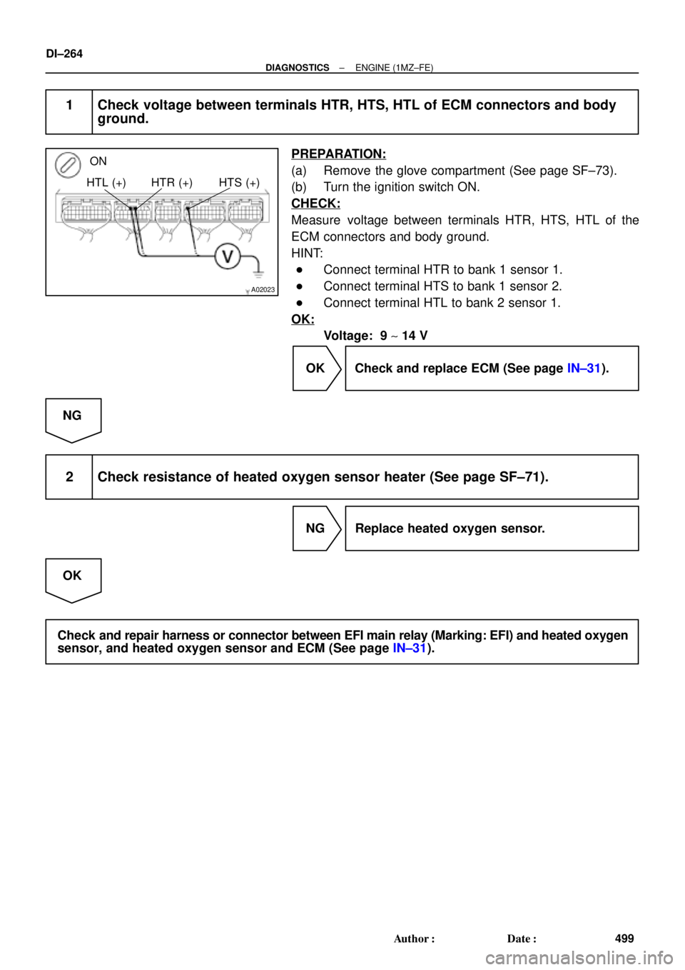
ON
HTL (+) HTR (+) HTS (+)
DI±264
± DIAGNOSTICSENGINE (1MZ±FE)
499 Author�: Date�:
1 Check voltage between terminals HTR, HTS, HTL of ECM connectors and body
ground.
PREPARATION:
(a) Remove the glove compartment (See page SF±73).
(b) Turn the ignition switch ON.
CHECK:
Measure voltage between terminals HTR, HTS, HTL of the
ECM connectors and body ground.
HINT:
�Connect terminal HTR to bank 1 sensor 1.
�Connect terminal HTS to bank 1 sensor 2.
�Connect terminal HTL to bank 2 sensor 1.
OK:
Voltage: 9 ~ 14 V
OK Check and replace ECM (See page IN±31).
NG
2 Check resistance of heated oxygen sensor heater (See page SF±71).
NG Replace heated oxygen sensor.
OK
Check and repair harness or connector between EFI main relay (Marking: EFI) and heated oxygen
sensor, and heated oxygen sensor and ECM (See page IN±31).
Page 1518 of 4592

1 V
0 V
200 m sec./Division
DI±306
± DIAGNOSTICSENGINE (1MZ±FE)
541 Author�: Date�:
(a) Connect the TOYOTA hand±held tester to the DLC3, or connect the pr")
FI6514
OX Signal Waveform (Oscilloscope)
1 V
0 V
200 m sec./Division
DI±306
± DIAGNOSTICSENGINE (1MZ±FE)
541 Author�: Date�:
(a) Connect the TOYOTA hand±held tester to the DLC3, or connect the probe of the oscilloscope between
terminals OXR1, OXL1, OXS and E1 of the ECM connector.
(b) Start engine and warm it up with all accessories switched OFF until water temp. is stable.
(c) Race the engine at 2,500 ~ 3,000 rpm for about 3 min.
(d) After confirming that the waveform of the heated oxygen sensor, bank 1, 2 sensor 1 (OXR1, OXL1),
oscillate around 0.5 V during feedback to the ECM, check the waveform of the heated oxygen sensor,
bank 1 sensor 2 (OXS).
HINT:
If there is a malfunction in the system, the waveform of the
heated oxygen sensor, bank 1 sensor 2 (OXS), is almost the
same as that of the heated oxygen sensor, bank 1, 2 sensor 1
(OXR1, OXL1), on the left.
There are some cases where, even though a malfunction
exists, the MIL may either light up or not light up.
INSPECTION PROCEDURE
HINT:
Read freeze frame data using TOYOTA hand±held theater or OBD II scan tool. Because freeze frame re-
cords the engine conditions when the malfunction is detected, when troubleshooting it is useful for determin-
ing whether the vehicle was running or stopped, the engine warmed up or not, the air±fuel ratio lean or rich,
etc. at the time of the malfunction.
1 Are there any other codes (besides DTC P0420) being output?
YES Go to relevant DTC chart.
NO
2 Check gas leakage on exhaust system.
NG Repair or replace.
OK
Page 1555 of 4592
± DIAGNOSTICSENGINE (1MZ±FE)
DI±343
578 Author�: Date�:
3 Check for open and short in harness and connector between ECM and A/F sen-
sors (bank 1, 2 sensor 1) (See page IN±31).
NG Repair or replace harness or connector.
OK
4 Check resistance of A/F sensor heater (See page SF±68).
NG Replace A/F sensor.
OK
5 Check air induction system (See page SF±1).
NG Repair or replace.
OK
6 Check EGR system (See page EC±11).
NG Replace EGR system.
OK
7 Check fuel pressure (See page SF±21).
NG Check and repair fuel pump, fuel pipe line and
filter (See page SF±1).
OK
Page 1559 of 4592
± DIAGNOSTICSENGINE (1MZ±FE)
DI±347
582 Author�: Date�:
3 Check for open and short in harness and connector between ECM and A/F sen-
sors (bank 1, 2 sensor 1) (See page IN±31).
NG Repair or replace harness or connector.
OK
4 Check resistance of A/F sensor heater (See page SF±68).
NG Replace A/F sensor.
OK
5 Check air induction system (See page SF±1).
NG Repair or replace.
OK
6 Check EGR system (See page EC±11).
NG Replace EGR system.
OK
7 Check fuel pressure (See page SF±21).
NG Check and repair fuel pump, fuel pipe line and
filter (See page SF±1).
OK
Page 1561 of 4592

HAFR (+)
± DIAGNOSTICSENGINE (1MZ±FE)
DI±349
584 Author�: Date�:
DTC P1135 A/F Sensor Heater Circuit Malfunction
(Bank 1 Sensor 1) (Only for California Spec.)
DTC P1155 A/F Sensor")
A02509
HAFL (+)
HAFR (+)
± DIAGNOSTICSENGINE (1MZ±FE)
DI±349
584 Author�: Date�:
DTC P1135 A/F Sensor Heater Circuit Malfunction
(Bank 1 Sensor 1) (Only for California Spec.)
DTC P1155 A/F Sensor Heater Circuit Malfunction
(Bank 2 Sensor 1) (Only for California Spec.)
CIRCUIT DESCRIPTION
Refer to DTC P0125 (Insufficient Coolant Temp. for Closed Loop Fuel Control (Only for California Spec.))
on page DI±249.
DTC No.DTC Detecting ConditionTrouble Area
P1135
When heater operates, heater current exceeds 8 A
(2 trip detection logic)�Open or in heater circuit of A/F sensors
(bank 1, 2 sensor 1)P1135
P1155Heater current of 0.25 A or less when heater operates
(2 trip detection logic)
(bank 1, 2 sensor 1)
�A/F sensors (bank 1, 2 sensor 1) heater
�ECM
WIRING DIAGRAM
Refer to DTC P0125 (Insufficient Coolant Temp. for Closed Loop Fuel Control (Only for California Spec.))
on page DI±249.
INSPECTION PROCEDURE
HINT:
Read freeze frame data using TOYOTA hand±held tester or OBD II scan tool. Because freeze frame records
the engine conditions when the malfunction is detected, when troubleshooting it is useful for determining
whether the vehicle was running or stopped, the engine warmed up or not, the air±fuel ratio lean or rich, etc.
at the time of the malfunction.
1 Check voltage between terminal HAFR, HAFL of ECM connector and body
ground.
PREPARATION:
(a) Remove glove compartment (See page SF±73).
(b) Turn the ignition switch ON.
CHECK:
Measure voltage between terminals HAFR, HAFL of the ECM
connector and body ground.
OK:
Voltage: 9 ~ 14 V
OK Check and replace ECM (See page IN±31).
NG
DI1K8±04
Page 1562 of 4592
DI±350
± DIAGNOSTICSENGINE (1MZ±FE)
585 Author�: Date�:
2 Check resistance of A/F sensor heaters (bank 1, 2 sensor 1) (See page SF±68).
NG Replace A/F sensors (bank 1, 2 sensor 1).
OK
Check and repair harness or connector between EFI main relay (Marking: EFI) and A/F sensors
(bank 1, 2 sensor 1), and A/F sensors (bank 1, 2 sensor 1) and ECM (See page IN±31).
Page 2001 of 4592
 (±)
H01249
ON
± DIAGNOSTICSSUPPLEMENTAL RESTRAINT SYSTEM
DI±789
1024 Author�: Date�:
2 Check source voltage.
PREPARATION:
Connect negative")
AB0119H01298H01299
Airbag Sensor Assembly
ON
ACC
IG2
(+) (±)
H01249
ON
± DIAGNOSTICSSUPPLEMENTAL RESTRAINT SYSTEM
DI±789
1024 Author�: Date�:
2 Check source voltage.
PREPARATION:
Connect negative (±) terminal cable to the battery.
CHECK:
(a) Turn ignition switch ON.
(b) Measure the voltage each of IG2 and ACC on the sensor
and operate electric system. (defogger, wiper, headlight,
heater blower, etc.)
OK:
Voltage: 10 ± 14 V
NG Check harness between battery and airbag sen-
sor assembly, and check battery and charging
system.
OK
3 Does SRS warning light turn off?
PREPARATION:
(a) Turn ignition switch to LOCK.
(b) Connect the steering wheel pad connector.
(c) Connect the front passenger airbag assembly connector.
(d) Connect the airbag sensor assembly connectors.
(e) Connect the side airbag assembly connectors.
(f) Connect the seat belt pretensioner connectors.
(g) Connect the side airbag sensor assembly connectors.
(h) Connect the front airbag sensor connectors.
(i) Turn ignition switch to ON.
CHECK:
Operate electric system (defogger, wiper, headlight, heater
blower, etc.) and check that SRS warning light goes off.
NO Check for DTCs. If a DTC is output, perform trou-
bleshooting for the DTC. If a normal code is out-
put, replace airbag sensor assembly.
YES
From the results of the above inspection, the malfunctioning part can now be considered normal.
To make sure of this, use the simulation method to check.
Page 2158 of 4592
 Prepare the TOYOTA hand±held tester.
(4) Connect the TOYOTA hand±held tester to the
DLC3 under the instrument panel lower pad.
(5) Tu")
FI3605
ON
OFFFlashing
0.13 Second
± DIAGNOSTICSENGINE
DI±7
(3) Prepare the TOYOTA hand±held tester.
(4) Connect the TOYOTA hand±held tester to the
DLC3 under the instrument panel lower pad.
(5) Turn the ignition switch ON and push the TOYOTA
hand±held tester ON.
(6) Switch the TOYOTA hand±held tester from the nor-
mal mode to the check mode. (Check that the MIL
flashes.)
NOTICE:
If the TOYOTA hand±held tester switches the ECM from
normal mode to check mode or vice±versa, or if the igni-
tion switch is turned from ON to ACC or LOCK during check
mode, the DTCs and freezed frame data will be erased.
(7) Start the engine. (The MIL goes out after the engine
start.)
(8) Simulate the conditions of the malfunction de-
scribed by the customer.
NOTICE:
Leave the ignition switch ON until you have checked the
DTC, etc.
(9) After simulating the malfunction conditions, use the
TOYOTA hand±held tester diagnosis selector to
check the DTCs and freezed frame data, etc.
HINT:
Take care not to turn the ignition switch OFF. Turning the ignition
switch OFF switches the diagnosis system from check mode to
normal mode. So all DTCs, etc. are erased.
(10) After checking the DTC, inspect the applicable cir-
cuit.
4. FAIL±SAFE CHART
If any of the following codes is recorded, the ECM enters fail±safe mode.
DTC No.Fail±Safe OperationFail±Safe Deactivation Conditions
P0105Ignition timing fixed at 5° BTDCReturned to normal condition
P0110Intake air temperature is fixed at 20°C (68°F)Returned to normal condition
P0115Engine coolant temperature is fixed at 80°(176°F)Returned to normal condition
P0120VTA is fixed at 0°The following condition must be repeated at least 2 times con-
secutively VTA ��0.1 V and � 0.95 V
P0141The heater circuit in witch an abnormality is detected is
turned offIgnition switch OFF
P1135The heater circuit in which an abnormality is detected is
turned offIgnition switch OFF
P1300
P1310Fuel cutIGF signal is detected for 2 consecutive ignitions