Page 799 of 4592

TMC made
(w/o Heater)TMMK made
(w/ Heater)1
2
2 332
± BODY")
BE0AW±03
Z16591
LR
MIRROR
OFF
LEFT SIDERIGHT SIDE
UP
OFF LEFT
RIGHT
DOWN
1 2 3
7 8 4
10 9 5
BE2357 h±10±2
6
N21184
TMMK made
(w/o Heater)
TMC made
(w/o Heater)TMMK made
(w/ Heater)1
2
2 332
± BODY ELECTRICALPOWER MIRROR CONTROL SYSTEM
BE±83
2303 Author�: Date�:
INSPECTION
1. Master switch left side:
INSPECT MIRROR CONTROL SWITCH CONTINUITY
Switch positionTester connectionSpecified condition
OFF±No continuity
UP1 ± 9, 6 ± 10Continuity
DOWN1 ± 10, 6 ± 9Continuity
LEFT5 ± 9, 6 ± 10Continuity
RIGHT5 ± 10, 6 ± 9Continuity
If continuity is not as specified, replace the switch.
2. Master switch right side:
INSPECT MIRROR CONTROL SWITCH CONTINUITY
Switch positionTester connectionSpecified condition
OFF±No continuity
UP6 ± 10, 7 ± 9Continuity
DOWN6 ± 9, 7 ± 10Continuity
LEFT6 ± 10, 8 ± 9Continuity
RIGHT6 ± 9, 8 ± 10Continuity
If continuity is not as specified, replace the switch.
3. INSPECT MIRROR MOTOR
(a) TMMK made (w/o Heater):
Connect the positive (+) lead from the battery to terminal
1 and negative (±) lead to terminal 2, check that the mirror
turns to left side.
(b) TMC made (w/o Heater):
Connect the positive (+) lead from the battery to terminal
3 and negative (±) lead to terminal 2, check that the mirror
turns to left side.
(c) TMMK made (w/ Heater):
Connect the positive (+) lead from the battery to terminal
3 and negative (±) lead to terminal 2, check that the mirror
turns to left side.
Page 800 of 4592
N21185
TMMK made
(w/o Heater)
TMC made
(w/o Heater)TMMK made
(w/ Heater)
N21186
TMMK made
(w/o Heater)
TMC made
(w/o Heater)TMMK made
(w/ Heater) BE±84
± BODY ELECTRICALPOWER MIRROR CONTROL SYSTEM
2304 Author�: Date�:
(d) Reverse the polarity and check that the mirror turns to
right side.
(e) TMMK made (w/o Heater):
Connect the positive (+) lead from the battery to terminal
3 and the negative (±) lead to terminal 2, check that the
mirror turns upward.
(f) TMC made (w/o Heater):
Connect the positive (+) lead from the battery to terminal
1 and the negative (±) lead to terminal 2, check that the
mirror turns upward.
(g) TMMK made (w/ Heater):
Connect the positive (+) lead from the battery to terminal
1 and the negative (±) lead to terminal 2, check that the
mirror turns upward.
Page 801 of 4592
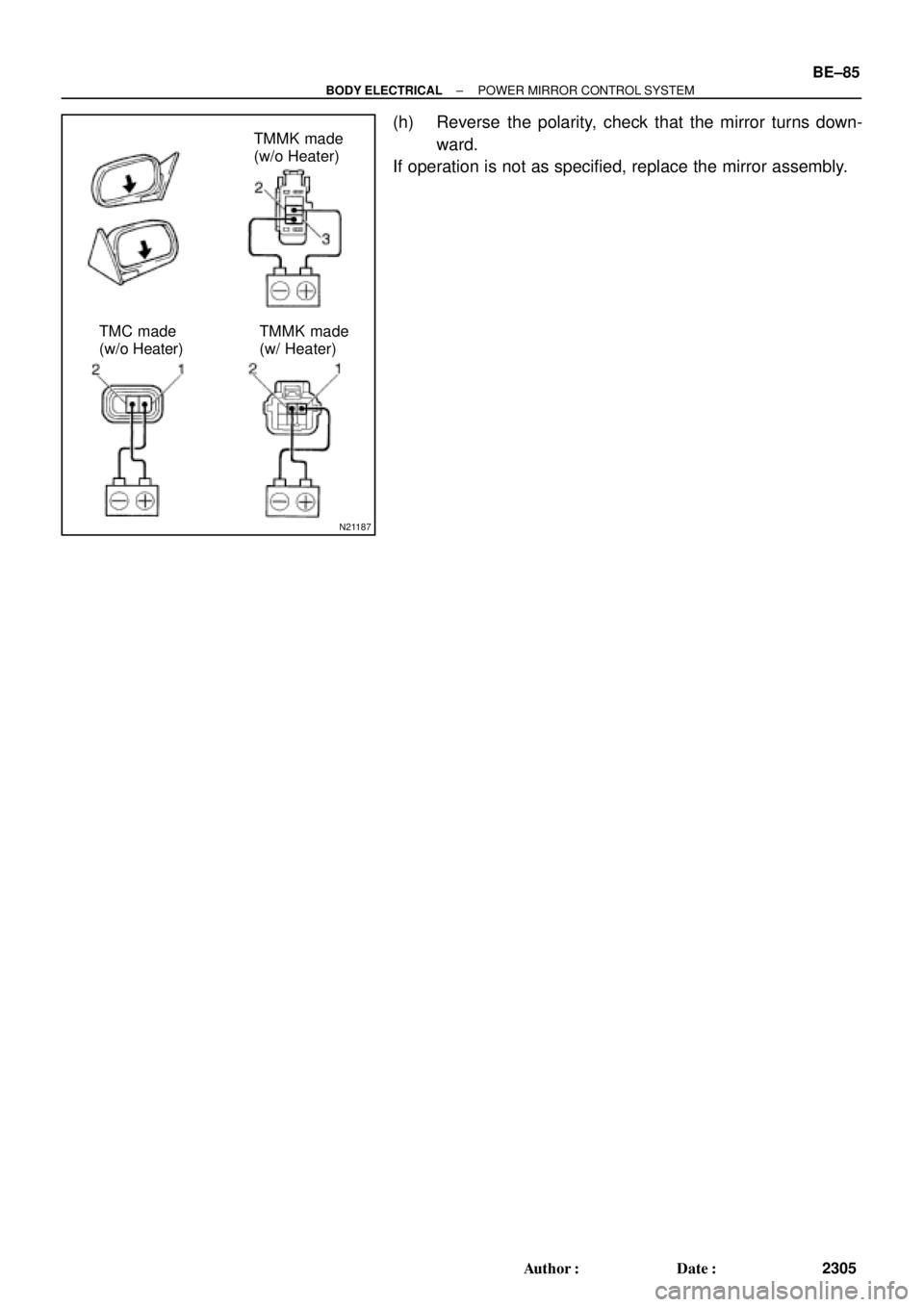
N21187
TMMK made
(w/o Heater)
TMC made
(w/o Heater)TMMK made
(w/ Heater)
± BODY ELECTRICALPOWER MIRROR CONTROL SYSTEM
BE±85
2305 Author�: Date�:
(h) Reverse the polarity, check that the mirror turns down-
ward.
If operation is not as specified, replace the mirror assembly.
Page 868 of 4592

H01759
UTA: IMI:
TOKAIRIKA:
Mirror
Mirror Shell
Gasket
Mirror w/case
Wire Retainer
Mirror w/case
Clip X4
BO0LB±01
H01760
Mirror w/caseGasket
Mirror HousingWire Retainer
H01761
Pivot Mirror Housing Forward
H01762
Mirror
Glass
Terminals
Mirror CaseScraper BO±24
± BODYOUTSIDE REAR VIEW MIRROR
2372 Author�: Date�:
DISASSEMBLY
1. IDENTIFY OUTSIDE REAR VIEW MIRROR
(a) w/ Power Rear View Mirror:
UTA:
The mirror moves smoothly when pressing the end of the
mirror inward.
(b) w/ Power Rear View Mirror:
IMI:
The mirror stutters when pressing the end of the mirror in-
ward.
(c) w/ Power Rear View Mirror:
TOKAIRIKA:
Equipped only on vehicles manufactured by TMC.
(d) w/o Power Rear View Mirror:
Mirrors manufactured by IMI
2. UTA:
DISASSEMBLE OUTSIDE REAR VIEW MIRROR
(a) Disconnect the battery.
(b) Press the inboard end of the mirror inward to access the
rear of the mirror w/case assembly.
(c) Unlatch both ends of the wire retainer, then remove the
mirror parts from the mirror housing.
NOTICE:
Be careful not to damage the wires on heated mirrors. Dis-
connect the wires from the back side of the heater.
3. IMI:
DISASSEMBLE OUTSIDE REAR VIEW MIRROR
(a) w/Heated Mirrors:
Disconnect the battery.
(b) Protect the door surface.
(c) Pivot the mirror housing to the forward position.
(d) Insert a scraper between the mirror and the case to re-
move the mirror.
NOTICE:
Be careful not to damage the wires on heated mirrors. Dis-
connect the wires from the back side of the heater.
Page 869 of 4592
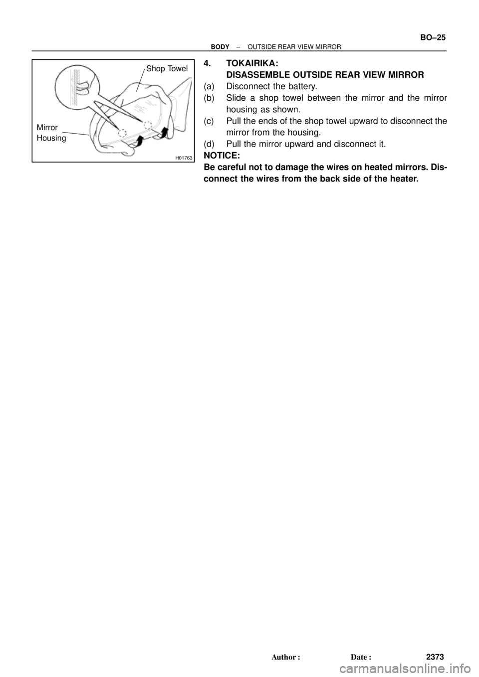
H01763
Mirror
Housing
Shop Towel
± BODYOUTSIDE REAR VIEW MIRROR
BO±25
2373 Author�: Date�:
4. TOKAIRIKA:
DISASSEMBLE OUTSIDE REAR VIEW MIRROR
(a) Disconnect the battery.
(b) Slide a shop towel between the mirror and the mirror
housing as shown.
(c) Pull the ends of the shop towel upward to disconnect the
mirror from the housing.
(d) Pull the mirror upward and disconnect it.
NOTICE:
Be careful not to damage the wires on heated mirrors. Dis-
connect the wires from the back side of the heater.
Page 870 of 4592

H01764
Gasket
Mirror w/case
Mirror HousingWire Retainer
BO0LC±01
H01765
50±60 mm
H01766
Glass
Case
Edge
H01767
Claw BClaw A BO±26
± BODYOUTSIDE REAR VIEW MIRROR
2374 Author�: Date�:
REASSEMBLY
1. UTA:
ASSEMBLE OUTSIDE REAR VIEW MIRROR
(a) w/Heated Mirrors:
Connect the heater wires.
(b) Install the wire retainer onto the mirror w/case assembly,
then press the mirror firmly into place to engage the 6 lugs
of the wire retainer.
NOTICE:
Pull the mirror edges to confirm the wire retainer lugs com-
pletely engage with the mirror housing.
(c) Reconnect the battery, then operate the mirror to its full
stop position.
2. IMI:
ASSEMBLE OUTSIDE REAR VIEW MIRROR
(a) From a distance of 50±60 mm, use a heat gun or hair dry-
er to heat the edge of the mirror case until the mirror case
becomes soft.
CAUTION:
Use extreme caution when using a heat gun or hair dryer.
Holding it too close can melt the mirror case.
(b) w/ Heated Mirrors:
Connect the heater wires.
(c) Before the the case cools down, position and snap the
new mirror glass into the case.
NOTICE:
Verify the glass case edge completely surrounds the mirror
glass.
(d) Allow the case to cool down before moving the mirror
back to its operating position.
(e) Recheck the fit between the glass and the case.
(f) Reconnect the battery, then operate the mirror to its full
stop position.
3. TOKAIRIKA:
ASSEMBLE OUTSIDE REAR VIEW MIRROR
(a) w/ Heated Mirrors:
Connect the heater wires.
(b) Connect the claws (A) and install the mirror into the mirror
housing.
(c) Push the mirror inward to connect the claws (B) onto the
mirror housing.
(d) Reconnect the battery, then operate the mirror to its full
stop position.
Page 917 of 4592
N20951
A
Instrument Panel Wire Harness
No.1 Defroster Nozzle Garnish
Defroster Nozzle Assembly A
A
RH Side Defroster Duct Nozzle
No.1
Side Defroster
Duct Nozzle
A
A
A
A
A
ANo.2 Heater Duct to
Register
No.3 Instrument
Panel Register
Assembly K
K
K
K
K
K
No.1 Heater Duct to
RegisterAAA
No.1 Instrument Panel
Regigter AssemblyNo.2 Instrument
Panel Register
AssemblyInstrument
Panel Center
Bracket
Instrument PanelGlove Box
Light Assembly
± BODYINSTRUMENT PANEL
BO±73
2421 Author�: Date�:
Page 923 of 4592
BO0MD±01
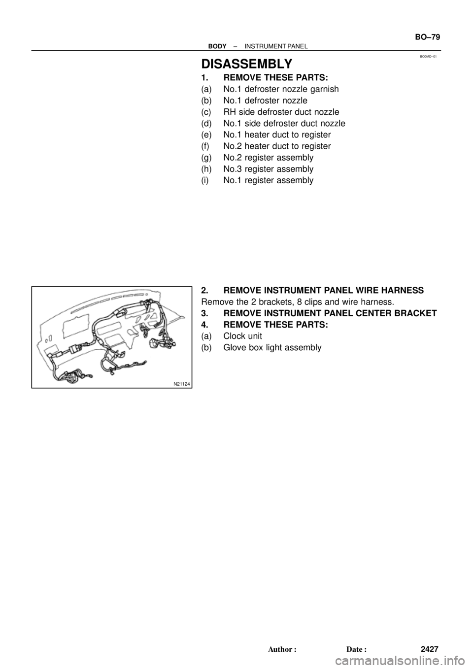
N21124
± BODYINSTRUMENT PANEL
BO±79
2427 Author�: Date�:
DISASSEMBLY
1. REMOVE THESE PARTS:
(a) No.1 defroster nozzle garnish
(b) No.1 defroster nozzle
(c) RH side defroster duct nozzle
(d) No.1 side defroster duct nozzle
(e) No.1 heater duct to register
(f) No.2 heater duct to register
(g) No.2 register assembly
(h) No.3 register assembly
(i) No.1 register assembly
2. REMOVE INSTRUMENT PANEL WIRE HARNESS
Remove the 2 brackets, 8 clips and wire harness.
3. REMOVE INSTRUMENT PANEL CENTER BRACKET
4. REMOVE THESE PARTS:
(a) Clock unit
(b) Glove box light assembly

TMC made
(w/o Heater)TMMK made
(w/ Heater)
N21186
TMMK made
(w/o Heater)
TMC made
(w/o Heater)TMMK made
(w/ Heater) BE±84
± BODY ELECTRICALPOWER MIRROR CONTROL SYSTEM
2")