Page 32 of 4592
N20283
N20245
Pin
Pin AC±32
± AIR CONDITIONINGAIR CONDITIONING UNIT
2514 Author�: Date�:
(e) Lubricate 2 new O±rings with compressor oil and install
the expansion valve.
(f) Install the expansion valve with the tubes to evaporator
with the 2 bolts.
Torque: 5.4 N´m (55 kgf´cm, 48 in.´lbf)
NOTICE:
When installing the expansion valve, take care so that the
packing is not jammed with the evaporator.
(g) Peel off the remaining packing paper and apply the pack-
ing to expansion valve.
4. INSTALL HEATER RADIATOR
(a) Install the heater radiator to heater case.
(b) Install the heater radiator pipe with 2 clips.
(c) Install the 3 clamps with the 3 screws.
5. INSTALL MODE SERVOMOTOR
(a) Install the servomotor with the 3 screws.
(b) Insert the drain of the plate to the pin and install plate.
Page 57 of 4592
AC21Z±01
N20692
I09156
I09155
I09154
AC±56
± AIR CONDITIONINGHEATER RADIATOR
2538 Author�: Date�:
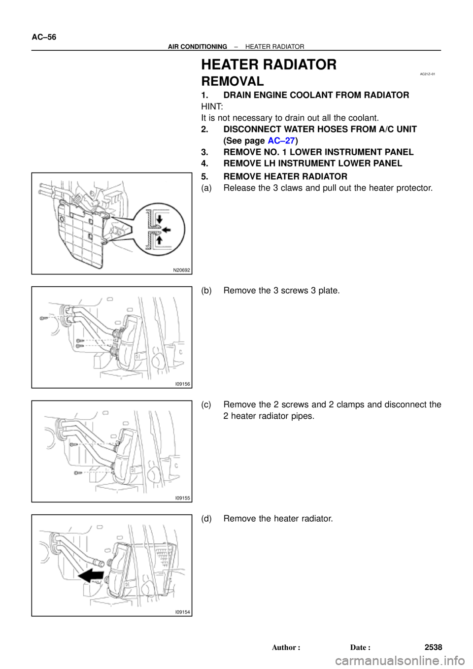
HEATER RADIATOR
REMOVAL
1. DRAIN ENGINE COOLANT FROM RADIATOR
HINT:
It is not necessary to drain out all the coolant.
2. DISCONNECT WATER HOSES FROM A/C UNIT
(See page AC±27)
3. REMOVE NO. 1 LOWER INSTRUMENT PANEL
4. REMOVE LH INSTRUMENT LOWER PANEL
5. REMOVE HEATER RADIATOR
(a) Release the 3 claws and pull out the heater protector.
(b) Remove the 3 screws 3 plate.
(c) Remove the 2 screws and 2 clamps and disconnect the
2 heater radiator pipes.
(d) Remove the heater radiator.
Page 58 of 4592
AC0MK±01
± AIR CONDITIONINGHEATER RADIATOR
AC±57
2539 Author�: Date�:
INSPECTION
INSPECT FINS FOR BLOCKAGE
If the fins are clogged, clean them with compressed air.
Page 59 of 4592
AC0ML±01
AC±58
± AIR CONDITIONINGHEATER RADIATOR
2540 Author�: Date�:
INSTALLATION
Installation is in the reverse order of removal (See page AC±56).
Page 71 of 4592
I09189
Heater Main
Relay
AC224±01
Z19533
34
5
1212 34 5 AC±70
± AIR CONDITIONINGHEATER MAIN RELAY
2552 Author�: Date�:
HEATER MAIN RELAY
INSPECTION
1. REMOVE HEATER MAIN RELAY FROM ENGINE
ROOM RELAY BLOCK NO. 1
2. INSPECT HEATER MAIN RELAY
(Marking: HTR RLY) CONTINUITY
ConditionTester connectionSpecified condition
Constant1 ± 3
2 ± 4Continuity
Apply B+ between
terminals 1 and 3.4 ± 5Continuity
If continuity is not as specified, replace the relay.
Page 72 of 4592
I09189
Magnetic Clutch
Relay
AC225±01
Z18060
35
1212 3
5
± AIR CONDITIONINGMAGNETIC CLUTCH RELAY
AC±71
2553 Author�: Date�:
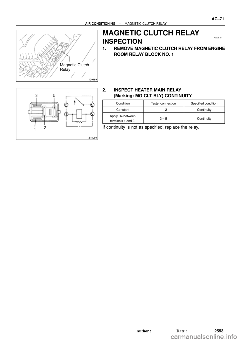
MAGNETIC CLUTCH RELAY
INSPECTION
1. REMOVE MAGNETIC CLUTCH RELAY FROM ENGINE
ROOM RELAY BLOCK NO. 1
2. INSPECT HEATER MAIN RELAY
(Marking: MG CLT RLY) CONTINUITY
ConditionTester connectionSpecified condition
Constant1 ± 2Continuity
Apply B+ between
terminals 1 and 2.3 ± 5Continuity
If continuity is not as specified, replace the relay.
Page 82 of 4592
AC0ND±02
Z19017
LH Lower Instrument
Panel
No.1 Lower Finish
Panel
Cowl Side Trim
Front Door Inside
Scuff PlateCenter Cluster Finish Panel
A/C Control Assembly
Glove Compartment
Cowl Side Trim
Air Inlet Damper Control Cable
Air Inlet Control Lever
Mode Switch
A/C Switch
Defogger Switch
Heater Control
Name Sheet
Heater Control Knob Heater Control BaseBlower Speed Control
SwitchFront Door Inside Scuff Plate
± AIR CONDITIONINGAIR CONDITIONING CONTROL ASSEMBLY
AC±81
2563 Author�: Date�:
COMPONENTS
Page 84 of 4592
AC0NF±02
± AIR CONDITIONINGAIR CONDITIONING CONTROL ASSEMBLY
AC±83
2565 Author�: Date�:
DISASSEMBLY
1. REMOVE A/C SWITCH AND DEFOGGER SWITCH
Using a screwdriver, release the claw and pull out the switch backward.
HINT:
Tape the screwdriver tip before use.
2. REMOVE HEATER CONTROL KNOBS
3. REMOVE HEATER CONTROL CABLE
4. REMOVE BLOWER SPEED CONTROL SWITCH
Remove the 2 screws and pull out the switch.
5. REMOVE MODE SWITCH
Remove the 2 screws and pull out the switch.
6. REMOVE HEATER CONTROL NAME SHEET
(a) Remove the 2 screws.
(b) Using a screwdriver, release the 4 claws and heater control name sheet.
HINT:
Tape the screwdriver tip before use.