Page 2510 of 4592
AB0119
I00145
I00177
ON
CMS
(±) (+)
DI±358
± DIAGNOSTICSCRUISE CONTROL SYSTEM
Main Switch Circuit (Cruise Control Switch)
CIRCUIT DESCRIPTION
When the cruise control main switch is turned OFF, the cruise control does not operate.
WIRING DIAGRAM
See page DI±340.
INSPECTION PROCEDURE
1 Check voltage between terminal CMS of cruise control ECU connector and body
ground.
PREPARATION:
(a) Remove the ECU with connector still connected.
(b) Turn ignition switch ON.
CHECK:
Measure voltage between terminal CMS of cruise control ECU
connector when main switch is held ON and OFF.
OK:
Main switchVoltage
OFF10 ± 14 V
ONBelow 0.5 V
OK Proceed to next circuit inspection shown on
problem symptoms table (See page DI±328).
NG
DI08Z±17
Page 2512 of 4592
I08465
Battery FL MAINB±G1
F9FL BLOCK
ALT1
F14 R±L
Instrument Panel J/B
2
1D
1K1
GAUGE
B±YIgnition Switch
4 IG1 AM1 2
W
B±RInstrument Panel J/B
1
1BAM12
1K CRUISE MAIN
Indicator Light
(in Combination Meter)
D DJ/CJ3
R±L10 7
C12 C12IE25
OODD
O J/CJ1
4
C16
Cruise Control ECU
PI DI±360
± DIAGNOSTICSCRUISE CONTROL SYSTEM
CRUISE MAIN Indicator Light Circuit
CIRCUIT DESCRIPTION
When the cruise control main switch is turned ON, CRUISE MAIN indicator light lights up.
WIRING DIAGRAM
DI090±20
Page 2513 of 4592
AB0119
I00144
I00178
ON
PI
(±) (+)
± DIAGNOSTICSCRUISE CONTROL SYSTEM
DI±361
INSPECTION PROCEDURE
1 Check voltage between terminals PI and GND of cruise control ECU connector.
PREPARATION:
Tun ignition switch ON.
CHECK:
Measure voltage between terminals PI and GND of cruise con-
trol ECU connector when main switch is ON and OFF.
OK:
Switch positionVoltage
OFF10 ± 16 V
ONBelow 1.2 V
OK Proceed to next circuit inspection shown on
problem symptoms table (See page DI±328).
NG
2 Check combination meter (See page BE±1).
NG Replace combination meter.
OK
Check and replace cruise control ECU
(See page IN±29).
Page 2515 of 4592
AB0119
I00169
I00179
ON
TC E1
± DIAGNOSTICSCRUISE CONTROL SYSTEM
DI±363
INSPECTION PROCEDURE
1 Check voltage between terminals Tc and E1 of DLC2.
PREPARATION:
Turn ignition switch ON.
CHECK:
Measure voltage between terminals Tc and E1 of DLC2.
OK:
Voltage: 10 ± 14 V
OK Proceed to next circuit inspection shown on
problem symptoms table (See page DI±328).
NG
2 Check harness and connector between cruise control ECU and DLC2, DLC2 and
body ground (See page IN±29).
NG Repair or replace harness or connector.
OK
Check and replace cruise control ECU
(See page IN±29).
Page 2544 of 4592
EC0AW±01
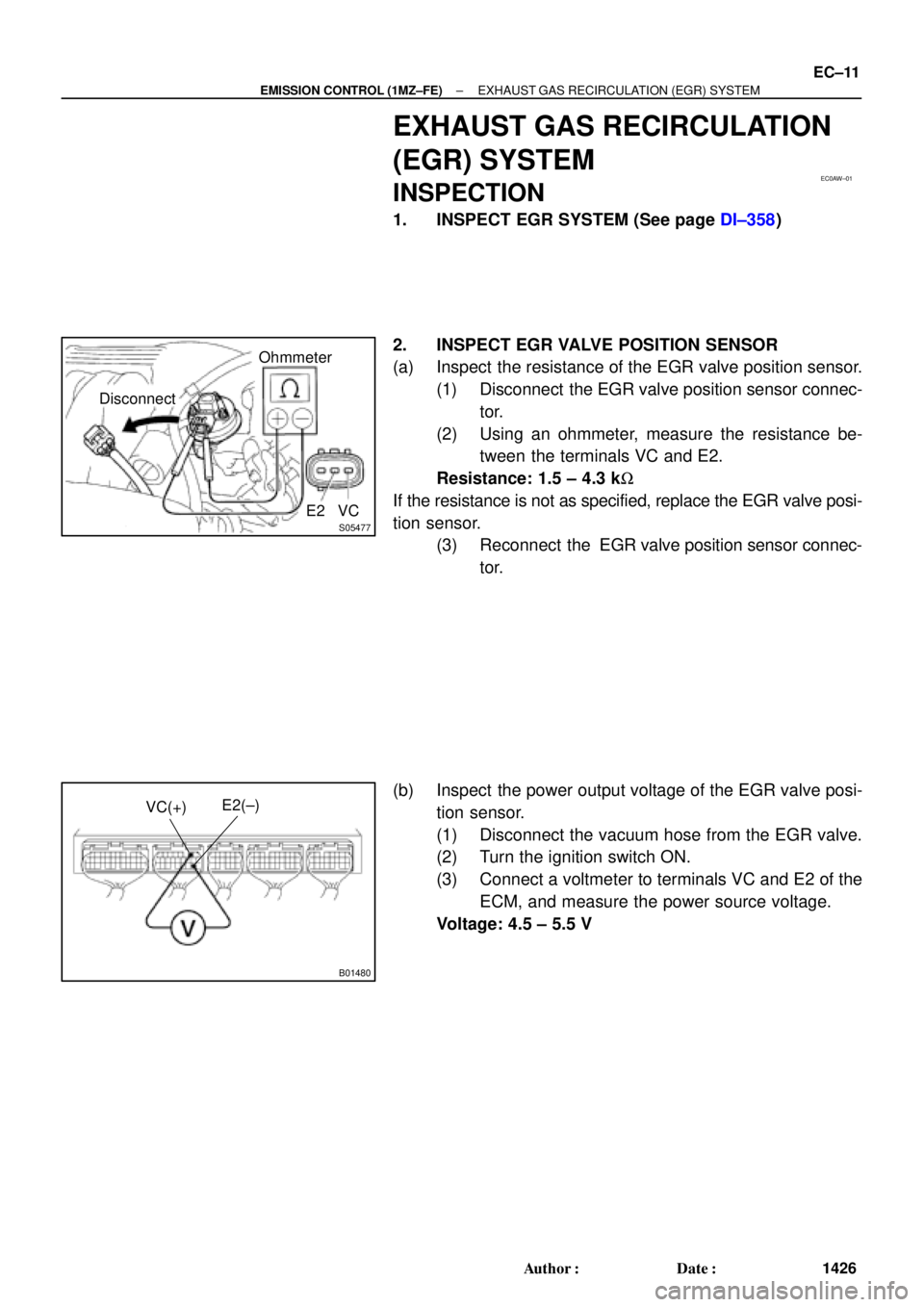
S05477
DisconnectOhmmeter
E2 VC
B01480
E2(±)
VC(+)
± EMISSION CONTROL (1MZ±FE)EXHAUST GAS RECIRCULATION (EGR) SYSTEM
EC±11
1426 Author�: Date�:
EXHAUST GAS RECIRCULATION
(EGR) SYSTEM
INSPECTION
1. INSPECT EGR SYSTEM (See page DI±358)
2. INSPECT EGR VALVE POSITION SENSOR
(a) Inspect the resistance of the EGR valve position sensor.
(1) Disconnect the EGR valve position sensor connec-
tor.
(2) Using an ohmmeter, measure the resistance be-
tween the terminals VC and E2.
Resistance: 1.5 ± 4.3 kW
If the resistance is not as specified, replace the EGR valve posi-
tion sensor.
(3) Reconnect the EGR valve position sensor connec-
tor.
(b) Inspect the power output voltage of the EGR valve posi-
tion sensor.
(1) Disconnect the vacuum hose from the EGR valve.
(2) Turn the ignition switch ON.
(3) Connect a voltmeter to terminals VC and E2 of the
ECM, and measure the power source voltage.
Voltage: 4.5 ± 5.5 V
Page 2552 of 4592
CO/HC
EM±1
1173 Author�: Date�:
CO/HC
INSPECTION
HINT:
This check is used only to determine whether or not the idle CO/
HC complies with regu")
EM07X±05
S04994
CO/HC Meter
± ENGINE MECHANICAL (5S±FE)CO/HC
EM±1
1173 Author�: Date�:
CO/HC
INSPECTION
HINT:
This check is used only to determine whether or not the idle CO/
HC complies with regulations.
1. INITIAL CONDITIONS
(a) Engine at normal operating temperature
(b) Air cleaner installed
(c) All pipes and hoses of air induction system connected
(d) All accessories switched OFF
(e) All vacuum lines properly connected
HINT:
All vacuum hoses for EGR system, etc. should be properly con-
nected.
(f) SFI system wiring connectors fully plugged
(g) Ignition timing checked correctly
(h) Transmission in neutral position
(i) Tachometer and CO/HC meter calibrated by hand
2. START ENGINE
3. RACE ENGINE AT 2,500 RPM FOR APPROX. 180 SE-
CONDS
4. INSERT CO/HC METER TESTING PROBE AT LEAST
40 cm (1.3 ft) INTO TAILPIPE DURING IDLING
5. IMMEDIATELY CHECK CO/HC CONCENTRATION AT
IDLE AND/OR 2,500 RPM
Complete the measuring within 3 minutes.
HINT:
When performing the 2 mode (2,500 rpm and idle) test, follow
the measurement order prescribed by the applicable local regu-
lations.
Page 2553 of 4592
CO/HC
1174 Author�: Date�:
If the CO/HC concentration does not comply with regulations,
troubleshoot in the order given below.
(1) Check oxygen sensor operation.
(Se")
EM±2
± ENGINE MECHANICAL (5S±FE)CO/HC
1174 Author�: Date�:
If the CO/HC concentration does not comply with regulations,
troubleshoot in the order given below.
(1) Check oxygen sensor operation.
(See page DI±66)
(2) See the table below for possible causes, then in-
spect and correct the applicable causes if neces-
sary.
COHCSymptomCauses
NormalHighRough idle1. Faulty ignitions:
� Incorrect timing
� Fouled, shorted or improperly gapped plugs
� Open or crossed hi
gh±tension cords� Oen or crossed high±tension cords
2. Incorrect valve clearance
3. Leaky EGR valve
4. Leaky intake and exhaust valves
5. Leaky cylinder
LowHighRough idle
(Fluctuating HC reading)1. Vacuum leaks:
� PCV hose
� EGR valve
� Intake manifold
� Throttle body
� IAC valve
� Brake booster line
2. Lean mixture causing misfire
HighHighRough idle
(Black smoke from exhaust)1. Restricted air filter
2. Faulty SFI system
� Faulty pressure regulator
� Defective ECT sensor
� Defective IAT sensor
� Faulty ECM
� Faulty injector
� Faulty throttle position sensor
� MAP sensor
Page 2554 of 4592
COMPRESSION
EM±3
1175 Author�: Date�:
COMPRESSION
INSPECTION
HINT:
If there is lack of power, excessive oil consumption or poor fuel
ec")
EM07Y±05
S05312
Compression
Gauge
± ENGINE MECHANICAL (5S±FE)COMPRESSION
EM±3
1175 Author�: Date�:
COMPRESSION
INSPECTION
HINT:
If there is lack of power, excessive oil consumption or poor fuel
economy, measure the compression pressure.
1. WARM UP AND STOP ENGINE
Allow the engine to warm up to normal operating temperature.
2. DISCONNECT IGNITION COIL CONNECTORS
3. REMOVE SPARK PLUGS (See page IG±1)
4. INSPECT CYLINDER COMPRESSION PRESSURE
(a) Insert a compression gauge into the spark plug hole.
(b) Fully open the throttle.
(c) While cranking the engine, measure the compression
pressure.
HINT:
Always use a fully charged battery to obtain engine speed of
250 rpm or more.
(d) Repeat steps (a) through (c) for each cylinder.
NOTICE:
This measurement must be done in as short a time as pos-
sible.
Compression pressure:
1,226 kPa (12.5 kgf/cm
2, 178 psi) or more
Minimum pressure: 981 kPa (10.0 kgf/cm
2, 142 psi)
Difference between each cylinder:
98 kPa (1.0 kgf/cm
2, 14 psi) or less
(e) If the cylinder compression in one or more cylinders is low,
pour a small amount of engine oil into the cylinder through
the spark plug hole and repeat steps (a) through (c) for
cylinders with low compression.
�If adding oil helps the compression, it is likely that
the piston rings and/or cylinder bore are worn or
damaged.
�If pressure stays low, a valve may be sticking or
seating is improper, or there may be leakage past
the gasket.
5. REINSTALL SPARK PLUGS (See page IG±1)
6. RECONNECT IGNITION COIL CONNECTORS
 (+)
DI±358
± DIAGNOSTICSCRUISE CONTROL SYSTEM
Main Switch Circuit (Cruise Control Switch)
CIRCUIT DESCRIPTION
When the cruise control main switch is turned OFF, the")

 (+)
± DIAGNOSTICSCRUISE CONTROL SYSTEM
DI±361
INSPECTION PROCEDURE
1 Check voltage between terminals PI and GND of cruise control ECU connector.
PREPARATION:
Tun igni")