Page 3575 of 4592

SA±19
1970 Author�: Date�:
DISASSEMBLY
1. CHECK DRIVE SHAFT
(a) Check to see that there is no pla")
SA08R±01
N00191
FA1615
Matchmarks
SA1443
Matchmarks
± SUSPENSION AND AXLEFRONT DRIVE SHAFT (5S±FE)
SA±19
1970 Author�: Date�:
DISASSEMBLY
1. CHECK DRIVE SHAFT
(a) Check to see that there is no play in the outboard joint
shaft.
(b) Check to see that the inboard joint shaft slides smoothly
in the thrust direction.
(c) Check to see that there is no remarkable play in the radial
direction of the inboard joint shaft.
(d) Check for damage to boots.
2. REMOVE INBOARD AND OUTBOARD JOINT BOOT
CLAMPS
(a) Using pliers, draw the hooks together and remove the
large inboard joint boot clamp.
(b) Using a side cutter, cut the small inboard and 2 outboard
joint boot clamps and remove them.
3. REMOVE INBOARD JOINT SHAFT
(a) Place matchmarks on the tripod, inboard and outboard-
joint shafts.
NOTICE:
Do not punch the marks.
(b) Remove the inboard joint shaft from the outboard joint
shaft.
4. REMOVE TRIPOD
(a) Using a snap ring expander, remove the snap ring.
(b) Using a snap ring expander, temporarily slide the snap
ring toward the outboard joint shaft side.
(c) Place matchmarks on the outboard joint shaft and tripod.
(d) Using a brass bar and hammer, remove the tripod from
the outboard joint shaft.
(e) Using a snap ring expander, remove the snap ring.
5. REMOVE INBOARD AND OUTBOARD JOINT BOOTS
Slide out the 2 boots.
NOTICE:
Do not disassemble the outboard joint.
Page 3578 of 4592

1973 Author�: Date�:
4. TEMPORARILY INSTALL OUTBOARD AND INBOARD
JOINT BOOTS AND")
F01747
Inboard Joint BootOutboard Joint Boot
Vinyl tape
R00764
SA±22
± SUSPENSION AND AXLEFRONT DRIVE SHAFT (5S±FE)
1973 Author�: Date�:
4. TEMPORARILY INSTALL OUTBOARD AND INBOARD
JOINT BOOTS AND NEW BOOT CLAMPS
HINT:
�Before installing the boots, wrap the spline of the drive
shaft in vinyl tape to prevent the boots from being dam-
aged.
�Before installing the boots, place 3 new clamps to the
small boot ends and large end (wheel side) and then
install boots to drive shaft.
5. INSTALL TRIPOD
(a) Using a snap ring expander, install a new snap ring.
(b) Place the beveled side of the tripod axial spline toward the
outboard joint shaft.
(c) Align the matchmarks placed before removal.
(d) Using a brass bar and hammer, tap in the tripod to the out-
board joint shaft.
NOTICE:
Do not tap the roller.
(e) Using a snap ring expander, install a new snap ring.
6. INSTALL BOOT TO OUTBOARD JOINT SHAFT
Before assembling the boot, coat the outboard joint and boot
with grease in the boot kit.
Grease capacity: (Color = Black)
100 ± 120 g (3.5 ± 4.2 oz.)
7. INSTALL INBOARD JOINT SHAFT TO OUTBOARD
JOINT SHAFT
(a) Coat the inboard joint and boot with grease in the boot kit.
Grease capacity: (Color = Yellow ocher)
125 ± 155 g (4.4 ± 5.5 oz)
(b) Align the matchmarks placed before removal, and install
the inboard joint shaft to the outboard joint shaft.
(c) Install the boot to the inboard joint shaft.
8. ASSEMBLE BOOT CLAMPS TO BOTH BOOTS
(a) Make sure that the 2 boots are on the shaft groove.
(b) Make sure that the 2 boots are not stretched or contracted
when the drive shaft is at standard length.
Drive shaft standard length
LH609.2 ± 2.0 mm (23.984 ± 0.079 in.)
RH867.3 ± 2.0 mm (34.146 ± 0.079 in.)
Page 3579 of 4592
F00615
R10353
SST
F00616
Clearance
SST
ABC
± SUSPENSION AND AXLEFRONT DRIVE SHAFT (5S±FE)
SA±23
1974 Author�: Date�:
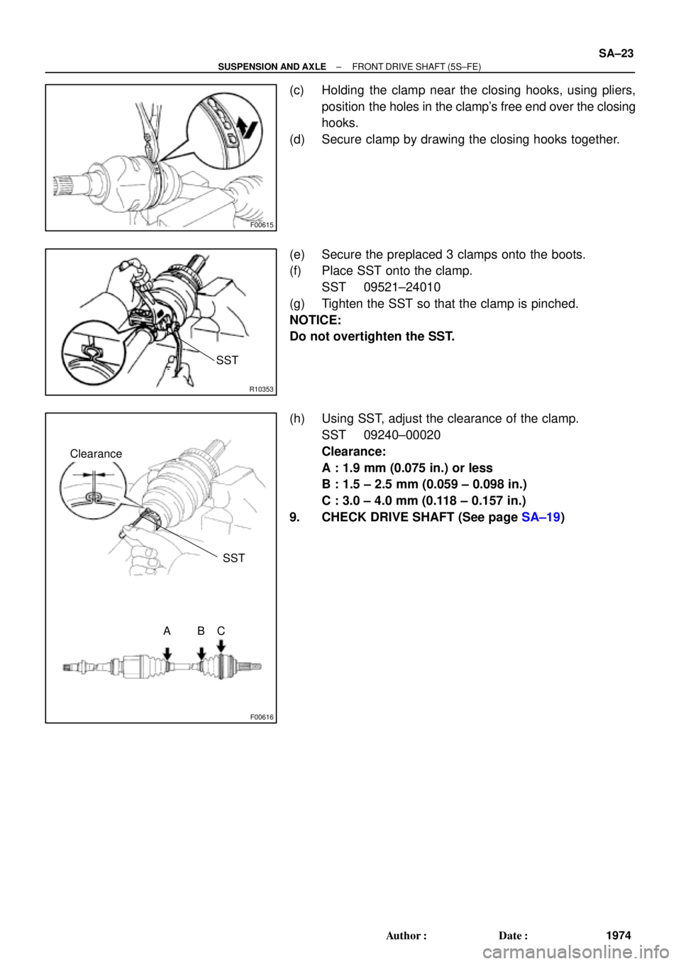
(c) Holding the clamp near the closing hooks, using pliers,
position the holes in the clamp's free end over the closing
hooks.
(d) Secure clamp by drawing the closing hooks together.
(e) Secure the preplaced 3 clamps onto the boots.
(f) Place SST onto the clamp.
SST 09521±24010
(g) Tighten the SST so that the clamp is pinched.
NOTICE:
Do not overtighten the SST.
(h) Using SST, adjust the clearance of the clamp.
SST 09240±00020
Clearance:
A : 1.9 mm (0.075 in.) or less
B : 1.5 ± 2.5 mm (0.059 ± 0.098 in.)
C : 3.0 ± 4.0 mm (0.118 ± 0.157 in.)
9. CHECK DRIVE SHAFT (See page SA±19)
Page 3581 of 4592
SA07H±01
W03141
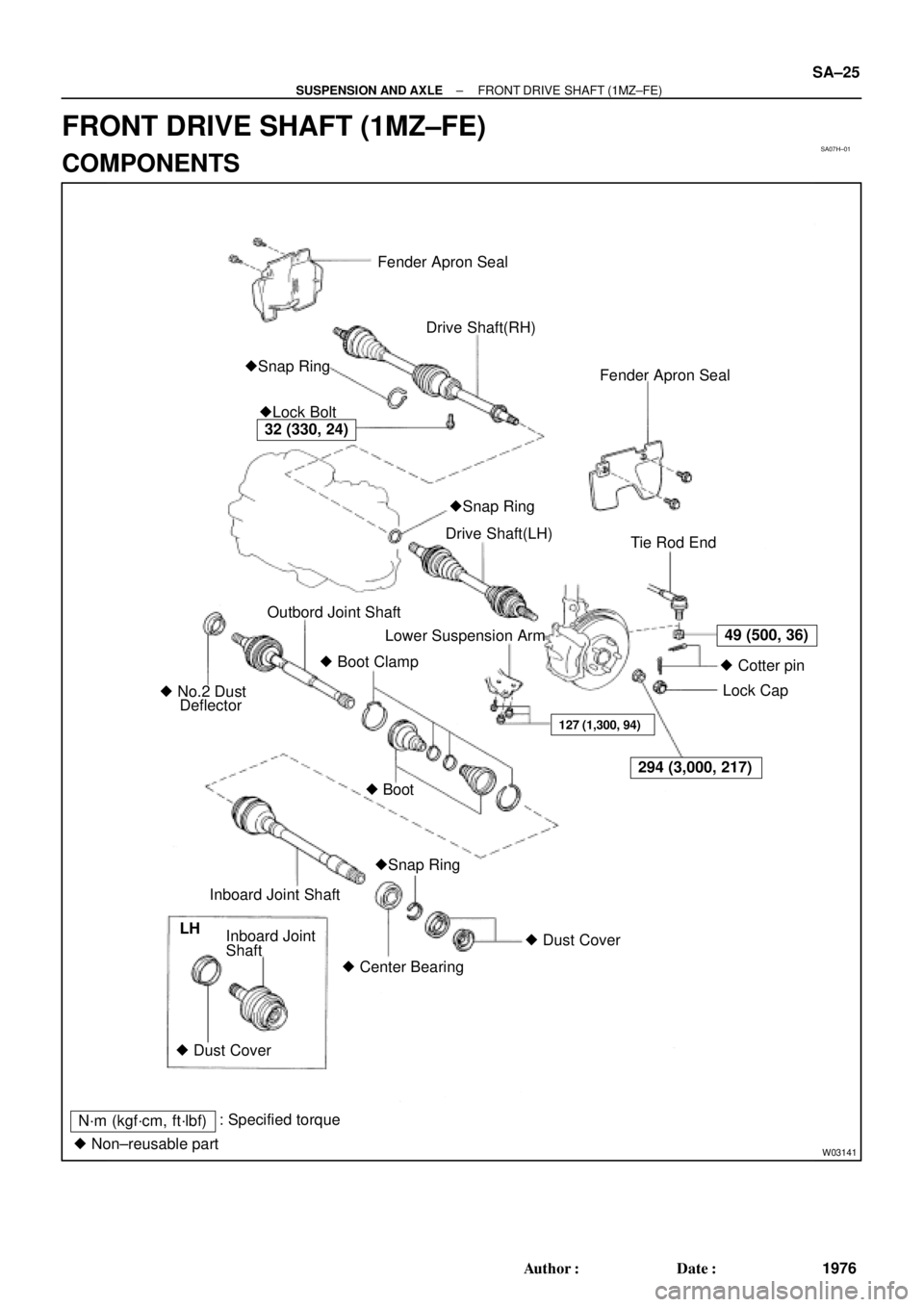
Fender Apron Seal
Drive Shaft(RH)
Fender Apron Seal
�Lock Bolt �Snap Ring
Tie Rod End
Lower Suspension Arm
� Boot Clamp Outbord Joint Shaft
� No.2 Dust
DeflectorDrive Shaft(LH)
�Snap Ring � Boot
32 (330, 24)
49 (500, 36)
294 (3,000, 217)
127 (1,300, 94)
� Cotter pin
Lock Cap
� Dust Cover
� Center Bearing Inboard Joint Shaft
Shaft Inboard Joint
� Dust Cover LH
N´m (kgf´cm, ft´lbf): Specified torque
� Non±reusable part�Snap Ring
± SUSPENSION AND AXLEFRONT DRIVE SHAFT (1MZ±FE)
SA±25
1976 Author�: Date�:
FRONT DRIVE SHAFT (1MZ±FE)
COMPONENTS
Page 3583 of 4592

SA±27
1978 Author�: Date�:
DISASSEMBLY
1. CHECK DRIVE SHAFT
(a) Check to see that there is no pl")
SA07J±01
R14967
W03190
matchmarks
SA0689
R09717
SST
± SUSPENSION AND AXLEFRONT DRIVE SHAFT (1MZ±FE)
SA±27
1978 Author�: Date�:
DISASSEMBLY
1. CHECK DRIVE SHAFT
(a) Check to see that there is no play in the outboard joint
shaft.
(b) Check to see that the inboard joint shaft slides smoothly
in the thrust direction.
(c) Check to see that there is no remarkable play in the radial
direction of the inboard joint shaft.
(d) Check for damage to boots.
2. REMOVE INBOARD AND OUTBOARD JOINT BOOT
CLAMPS
(a) Using pliers, draw the hooks together and remove the
large inboard joint boot clamp.
(b) Using a side cutter, cut the small inboard and 2 outboard
joint boot clamps and remove them.
3. REMOVE INBOARD JOINT SHAFT FROM OUTBOARD
JOINT SHAFT
(a) Place matchmarks on the inboard and outboard joint
shafts.
NOTICE:
Do not punch the marks.
(b) Using a snap ring expander, pull out the outboard joint
shaft expanding the snap ring.
4. REMOVE INBOARD AND OUTBOARD JOINT BOOTS
Slide out the 2 boots.
5. REMOVE DUST COVER
�(LH drive shaft)
Using a screwdriver and hammer, remove the dust cover from
the inboard joint shaft.
�(RH drive shaft)
Using a press, remove the dust cover from the inboard joint
shaft.
6. RH DRIVE SHAFT:
DISASSEMBLE INBOARD JOINT SHAFT
(a) Using SST and a press, remove the dust cover.
SST 09950±00020
(b) Using a snap ring expander, remove the snap ring.
Page 3586 of 4592

1981 Author�: Date�:
4. TEMPORARILY INSTALL OUTBOARD AND INBOARD
JOINT BO")
W03195
Inboard Joint BootOutboard Joint Boot
Vinyl Tape
W03196
R14973
SA±30
± SUSPENSION AND AXLEFRONT DRIVE SHAFT (1MZ±FE)
1981 Author�: Date�:
4. TEMPORARILY INSTALL OUTBOARD AND INBOARD
JOINT BOOTS AND NEW BOOT CLAMPS
HINT:
�Before installing the boots, wrap the spline of the drive
shaft in vinyl tape to prevent the boots from being dam-
aged.
�Before installing the boots, place 3 new clamps to the
small boot ends and large end (wheel side) and then
install boots to drive shaft.
5. INSTALL INBOARD JOINT SHAFT TO OUTBOARD
JOINT SHAFT
Align the matchmarks placed at removal, and using a snap ring
expander, put in the inboard joint shaft expanding the snap ring.
6. INSTALL BOOT TO OUTBOARD JOINT
Before assembling the boot, pack the outboard joint and boot
with grease in the boot kit.
Grease capacity: (Color = Black)
105 ± 125 g (3.7 ± 4.4 oz.)
7. INSTALL BOOT TO INBOARD JOINT SHAFT
(a) Pack the inboard joint and boot with grease in the boot kit.
Grease capacity: (Color = Gray)
Joint side: 142.5 ± 157.5 g (5.0 ± 5.6 oz.)
Boot side: 52.5 ± 57.5 g (2.1 ± 2.3 oz.)
(b) Install the boot to the inboard joint shaft.
8. ASSEMBLE BOOT CLAMPS TO BOTH BOOTS
(a) Make sure that the 2 boots are on the shaft groove.
(b) Make sure that the 2 boots are not stretched or contracted
when the drive shaft is at standard length.
Drive shaft standard length:
M/T LH601.5 ± 2.0 mm (23.681 ± 0.079 in.)
RH871.6 ± 2.0 mm (34.315 ± 0.079 in.)
A/T LH586.0 ± 2.0 mm (23.071 ± 0.079 in.)
RH881.6 ± 2.0 mm (34.709 ± 0.079 in.)
(c) Holding the clamp near the closing hooks, using pliers,
position the holes in the clamp's free end over the closing
hooks.
(d) Secure clamp by drawing the closing hooks together.
Page 3587 of 4592
R10353
SST
F02023
Clearance
SST
ABC
± SUSPENSION AND AXLEFRONT DRIVE SHAFT (1MZ±FE)
SA±31
1982 Author�: Date�:
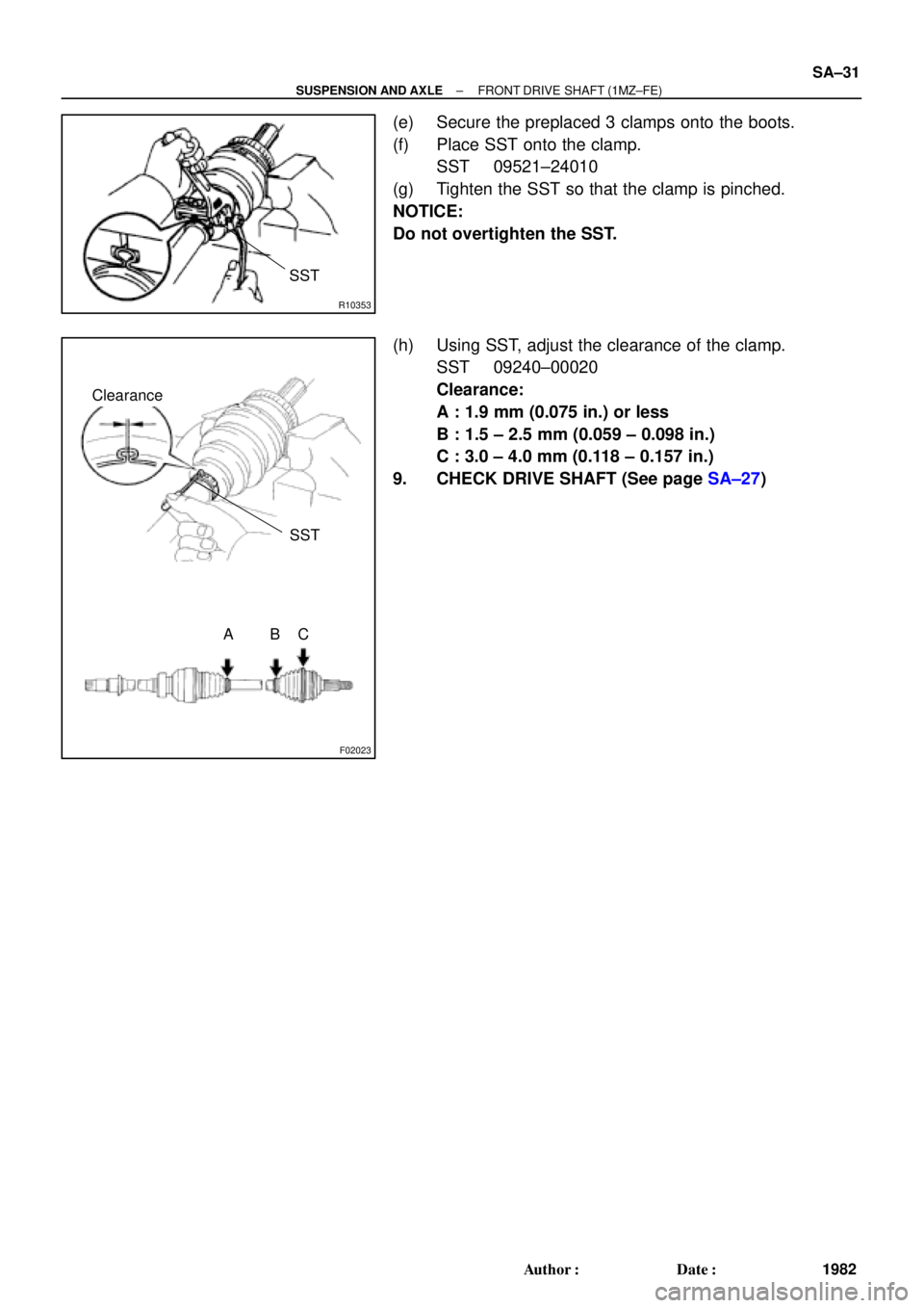
(e) Secure the preplaced 3 clamps onto the boots.
(f) Place SST onto the clamp.
SST 09521±24010
(g) Tighten the SST so that the clamp is pinched.
NOTICE:
Do not overtighten the SST.
(h) Using SST, adjust the clearance of the clamp.
SST 09240±00020
Clearance:
A : 1.9 mm (0.075 in.) or less
B : 1.5 ± 2.5 mm (0.059 ± 0.098 in.)
C : 3.0 ± 4.0 mm (0.118 ± 0.157 in.)
9. CHECK DRIVE SHAFT (See page SA±27)
Page 3631 of 4592
A + B: 0° �")
SA3213
Front A
DB
C
F02245
F02246
SA0028
Front AB
A B
A: Inside
B: Outside
± SUSPENSION AND AXLEFRONT WHEEL ALIGNMENT
SA±3
510 Author�: Date�:
5. INSPECT TOE±IN
Toe±in:
Toe±in
(total)A + B: 0° ± 12' (0° ± 0.2°)
C ± D: 0 ± 2 mm (0 ± 0.08 in.)
If the toe±in is not within the specified value, adjust it at the rack
ends.
6. ADJUST TOE±IN
(a) Using pliers, remove the rack boot set clips.
(b) Loosen the tie rod end lock nuts.
(c) Turn the right and left rack ends by an equal amount to
adjust the toe±in.
HINT:
Try to adjust the toe±in to the center of the specified value.
(d) Make sure that the lengths of the right and left rack ends
are the same.
Rack end length difference: 1.5 mm (0.059 in.) or less
(e) Torque the tie rod end lock nuts.
Torque: 74 N´m (750 kgf´cm, 54 ft´lbf)
(f) Place the boots on the seats and using pliers, install the
clips.
HINT:
Make sure that the boots are not twisted.
7. INSPECT WHEEL ANGLE
Turn the steering wheel fully, and measure the turning angle.
Wheel turning angle:
Inside wheel35°50' ± 2° (35.84° ± 2°)
Outside wheel: Reference31°28' (31.47°)
If the right and left inside wheel angles differ from the specified
value, check the right and left rack end lengths.