Page 2682 of 4592
A01804
A05053
P12764
SST RH
P12762
SST LH
A05055
± ENGINE MECHANICAL (1MZ±FE)TIMING BELT
EM±17
1303 Author�: Date�:
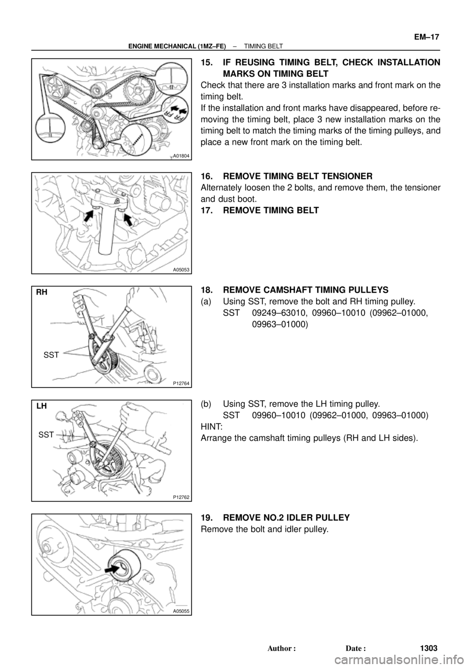
15. IF REUSING TIMING BELT, CHECK INSTALLATION
MARKS ON TIMING BELT
Check that there are 3 installation marks and front mark on the
timing belt.
If the installation and front marks have disappeared, before re-
moving the timing belt, place 3 new installation marks on the
timing belt to match the timing marks of the timing pulleys, and
place a new front mark on the timing belt.
16. REMOVE TIMING BELT TENSIONER
Alternately loosen the 2 bolts, and remove them, the tensioner
and dust boot.
17. REMOVE TIMING BELT
18. REMOVE CAMSHAFT TIMING PULLEYS
(a) Using SST, remove the bolt and RH timing pulley.
SST 09249±63010, 09960±10010 (09962±01000,
09963±01000)
(b) Using SST, remove the LH timing pulley.
SST 09960±10010 (09962±01000, 09963±01000)
HINT:
Arrange the camshaft timing pulleys (RH and LH sides).
19. REMOVE NO.2 IDLER PULLEY
Remove the bolt and idler pulley.
Page 2688 of 4592
A02338
5th4th3rd
2nd
6th
1st
A05064
1.27 mm
Hexagon
Wrench
A05065
A05066
1.27 mm
Hexagon
Wrench
± ENGINE MECHANICAL (1MZ±FE)TIMING BELT
EM±23
1309 Author�: Date�:
7. INSTALL TIMING BELT
NOTICE:
The engine should be cold.
(a) Remove any oil or water on the pulleys, and keep them
clean.
NOTICE:
Only wipe the pulleys; do not use any cleansing agent.
(b) Face the front mark on the timing belt forward.
(c) Align the installation mark on the timing belt with the tim-
ing mark of the crankshaft timing pulley.
(d) Align the installation marks on the timing belt with the tim-
ing marks of the camshaft timing pulleys.
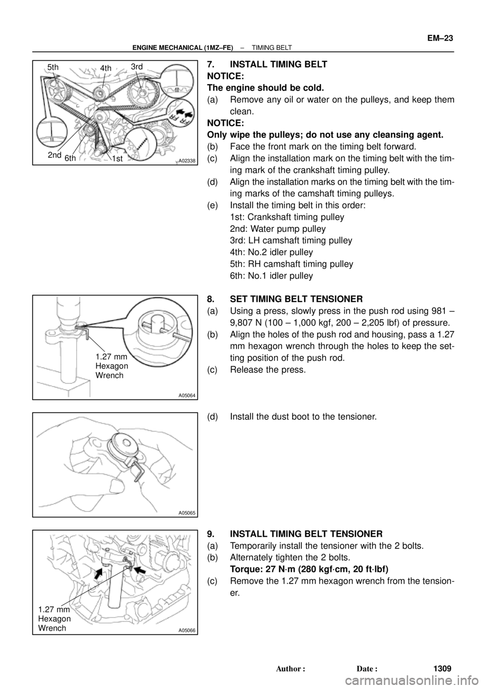
(e) Install the timing belt in this order:
1st: Crankshaft timing pulley
2nd: Water pump pulley
3rd: LH camshaft timing pulley
4th: No.2 idler pulley
5th: RH camshaft timing pulley
6th: No.1 idler pulley
8. SET TIMING BELT TENSIONER
(a) Using a press, slowly press in the push rod using 981 ±
9,807 N (100 ± 1,000 kgf, 200 ± 2,205 lbf) of pressure.
(b) Align the holes of the push rod and housing, pass a 1.27
mm hexagon wrench through the holes to keep the set-
ting position of the push rod.
(c) Release the press.
(d) Install the dust boot to the tensioner.
9. INSTALL TIMING BELT TENSIONER
(a) Temporarily install the tensioner with the 2 bolts.
(b) Alternately tighten the 2 bolts.
Torque: 27 N´m (280 kgf´cm, 20 ft´lbf)
(c) Remove the 1.27 mm hexagon wrench from the tension-
er.
Page 2694 of 4592
A05070
Timing Belt
Gasket No.2 Timing Belt Cover
RH Engine Mounting Bracket
Crankshaft
Pulley No.1 Timing Belt Cover
Gasket
Engine Wire
Protector
No.2 Idler Pulley
RH Camshaft Timing Pulley
LH Camshaft
Timing Pulley
Timing Belt TensionerTiming Belt Guide
No.2 Generator
Bracket
Dust Boot
N´m (kgf´cm, ft´lbf) : Specified torque
* For use with SST� Non±reusable part
28 (290, 21)
215 (2,200, 159)
125 (1,300, 94)
*88 (900, 65)
27 (280, 20)
43 (440, 32)
125 (1,300, 94)
± ENGINE MECHANICAL (1MZ±FE)CYLINDER HEAD
EM±29
1315 Author�: Date�:
Page 2779 of 4592
S05295
CORRECT
WRONG
S05542
Ohmmeter
IG0147
Megger
Ground
S03776
IG±2
± IGNITION (5S±FE)IGNITION SYSTEM
1684 Author�: Date�:
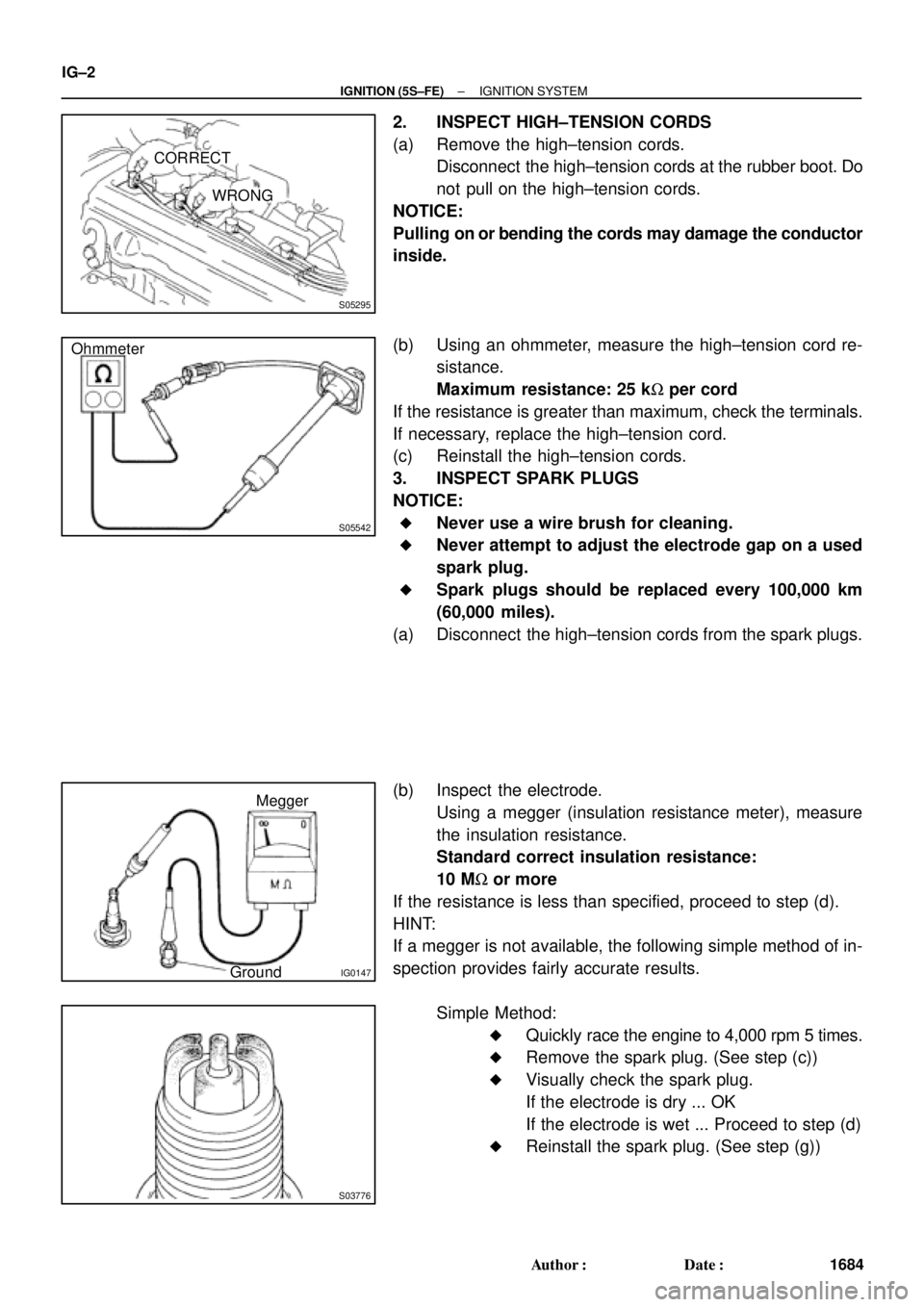
2. INSPECT HIGH±TENSION CORDS
(a) Remove the high±tension cords.
Disconnect the high±tension cords at the rubber boot. Do
not pull on the high±tension cords.
NOTICE:
Pulling on or bending the cords may damage the conductor
inside.
(b) Using an ohmmeter, measure the high±tension cord re-
sistance.
Maximum resistance: 25 kW per cord
If the resistance is greater than maximum, check the terminals.
If necessary, replace the high±tension cord.
(c) Reinstall the high±tension cords.
3. INSPECT SPARK PLUGS
NOTICE:
�Never use a wire brush for cleaning.
�Never attempt to adjust the electrode gap on a used
spark plug.
�Spark plugs should be replaced every 100,000 km
(60,000 miles).
(a) Disconnect the high±tension cords from the spark plugs.
(b) Inspect the electrode.
Using a megger (insulation resistance meter), measure
the insulation resistance.
Standard correct insulation resistance:
10 MW or more
If the resistance is less than specified, proceed to step (d).
HINT:
If a megger is not available, the following simple method of in-
spection provides fairly accurate results.
Simple Method:
�Quickly race the engine to 4,000 rpm 5 times.
�Remove the spark plug. (See step (c))
�Visually check the spark plug.
If the electrode is dry ... OK
If the electrode is wet ... Proceed to step (d)
�Reinstall the spark plug. (See step (g))
Page 2804 of 4592
IN00U±22
N17080
Filler Cap
Float
Reservoir Tank
� Grommet
Clip
Slotted Spring Pin
: Specified torque
� Non±reusable partCylinder
Piston
Push Rod
Washer
Snap Ring
Boot
� Gasket
Lock Nut
Clevis Pin
Clevis
N´m (kgf´cm, ft´lbf)
12 (120, 9)
15 (155, 11)
± INTRODUCTIONHOW TO USE THIS MANUAL
IN±1
1 Author�: Date�:
HOW TO USE THIS MANUAL
GENERAL INFORMATION
1. INDEX
An INDEX is provided on the first page of each section to guide you to the item to be repaired. To assist you
in finding your way through the manual, the Section Title and major heading are given at the top of every
page.
2. GENERAL DESCRIPTION
At the beginning of each section, a General Description is given that pertains to all repair operations con-
tained in that section.
Read these precautions before starting any repair task.
3. TROUBLESHOOTING
TROUBLESHOOTING tables are included for each system to help you diagnose the problem and find the
cause. The fundamentals of how to proceed with troubleshooting are described on page IN±21.
Be sure to read this before performing troubleshooting.
4. PREPARATION
Preparation lists the SST (Special Service Tools), recommended tools, equipment, lubricant and SSM (Spe-
cial Service Materials) which should be prepared before beginning the operation and explains the purpose
of each one.
5. REPAIR PROCEDURES
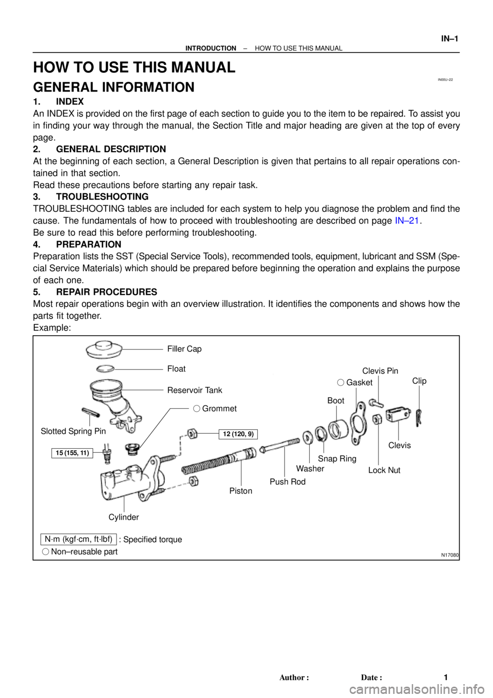
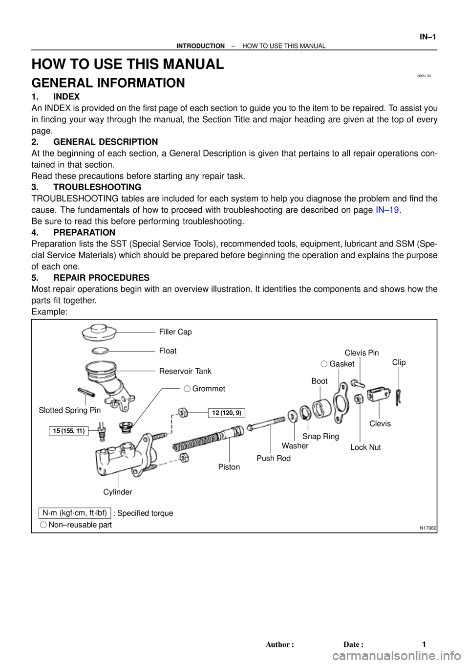
Most repair operations begin with an overview illustration. It identifies the components and shows how the
parts fit together.
Example:
Page 2847 of 4592
IN00U±30
N17080
Filler Cap
Float
Reservoir Tank
� Grommet
Clip
Slotted Spring Pin
: Specified torque
� Non±reusable partCylinder
Piston
Push Rod
Washer
Snap Ring
Boot
� Gasket
Lock Nut
Clevis Pin
Clevis
N´m (kgf´cm, ft´lbf)
12 (120, 9)
15 (155, 11)
± INTRODUCTIONHOW TO USE THIS MANUAL
IN±1
1 Author�: Date�:
HOW TO USE THIS MANUAL
GENERAL INFORMATION
1. INDEX
An INDEX is provided on the first page of each section to guide you to the item to be repaired. To assist you
in finding your way through the manual, the Section Title and major heading are given at the top of every
page.
2. GENERAL DESCRIPTION
At the beginning of each section, a General Description is given that pertains to all repair operations con-
tained in that section.
Read these precautions before starting any repair task.
3. TROUBLESHOOTING
TROUBLESHOOTING tables are included for each system to help you diagnose the problem and find the
cause. The fundamentals of how to proceed with troubleshooting are described on page IN±19.
Be sure to read this before performing troubleshooting.
4. PREPARATION
Preparation lists the SST (Special Service Tools), recommended tools, equipment, lubricant and SSM (Spe-
cial Service Materials) which should be prepared before beginning the operation and explains the purpose
of each one.
5. REPAIR PROCEDURES
Most repair operations begin with an overview illustration. It identifies the components and shows how the
parts fit together.
Example:
Page 2911 of 4592
B06384
No.2 Timing Belt CoverTiming Belt
Gasket
Timing Belt Guide
No.2 Generator
Bracket RH Engine Mounting Bracket
Crankshaft
PulleyGasket
Engine Wire
Protector
RH Camshaft Timing Pulley
No.2 Idler Pulley
Crankshaft
Timing PulleyDust Boot
Timing Belt Plate Plate Washer
�
Timing Belt Tensioner
N´m (kgf´cm, ft´lbf) : Specified torque
� Non±reusable part No.1 Timing Belt Cover
LH Camshaft
Timing Pulley
No.1 Idler Pulley
� Precoated part
* For use with SST
28 (290, 21)
215 (2,200, 159)
125 (1,300, 94)*88 (900, 65)43 (440, 32)
34 (350, 25)
27 (280, 20)
125 (1,300, 94)
LU±6
± LUBRICATION (1MZ±FE)OIL PUMP
1670 Author�: Date�:
Page 2930 of 4592
MA00N±01
N01022
± MAINTENANCECHASSIS
MA±7
50 Author�: Date�:
CHASSIS
INSPECTION
1. INSPECT STEERING LINKAGE
(a) Check the steering wheel freeplay. (See page SR±8)
(b) Check the steering linkage for looseness or damage.
Check that:
�Tie rod ends do not have excessive play.
�Dust seals and boots are not damaged.
�Boot clamps are not loose.
2. INSPECT SRS AIRBAG (See page RS±2)
3. INSPECT STEERING GEAR HOUSING OIL
Check the steering gear housing for oil leakage.
4. INSPECT DRIVE SHAFT BOOTS
Check the drive shaft boots for clamp looseness, leakage or
damage.
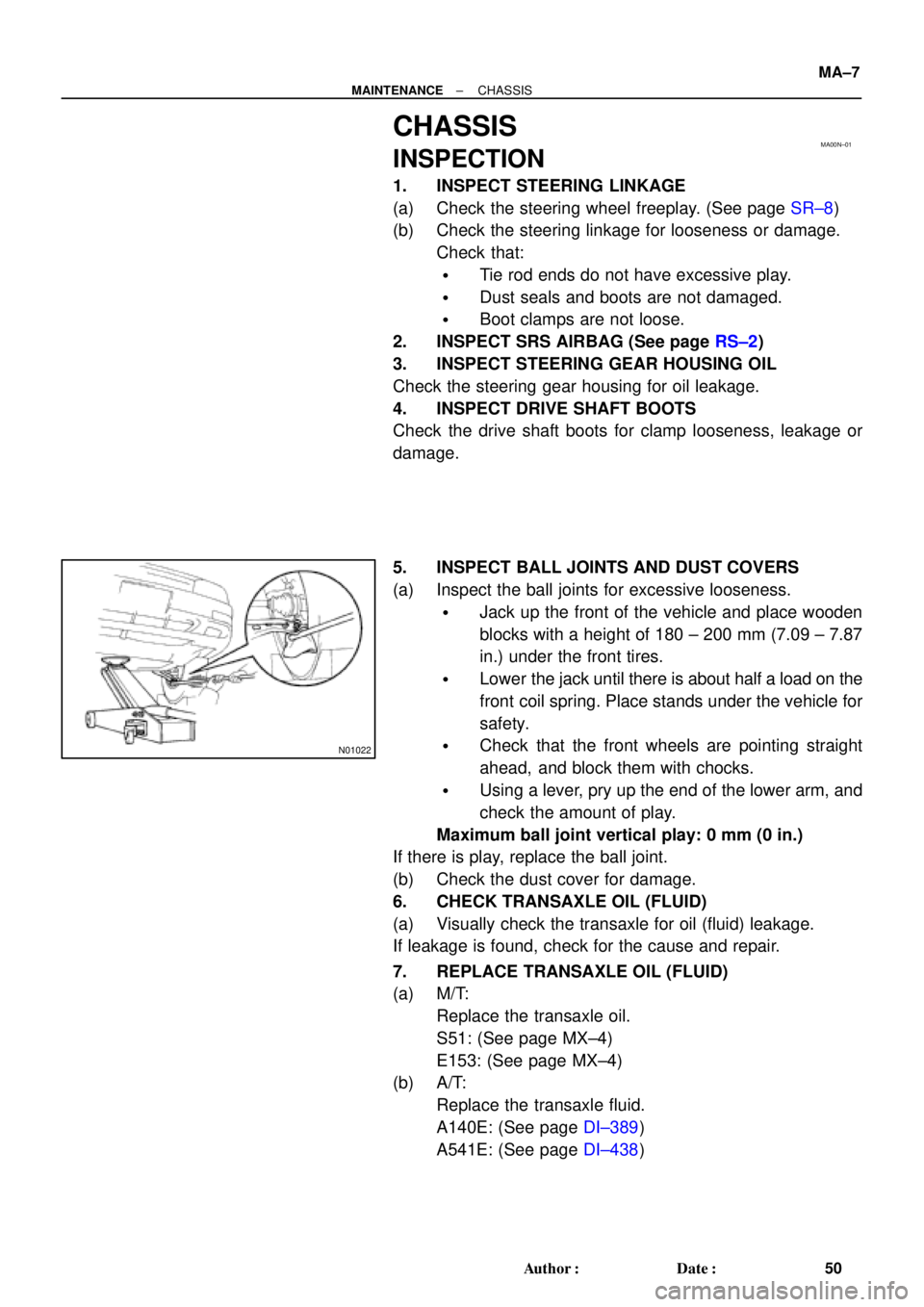
5. INSPECT BALL JOINTS AND DUST COVERS
(a) Inspect the ball joints for excessive looseness.
�Jack up the front of the vehicle and place wooden
blocks with a height of 180 ± 200 mm (7.09 ± 7.87
in.) under the front tires.
�Lower the jack until there is about half a load on the
front coil spring. Place stands under the vehicle for
safety.
�Check that the front wheels are pointing straight
ahead, and block them with chocks.
�Using a lever, pry up the end of the lower arm, and
check the amount of play.
Maximum ball joint vertical play: 0 mm (0 in.)
If there is play, replace the ball joint.
(b) Check the dust cover for damage.
6. CHECK TRANSAXLE OIL (FLUID)
(a) Visually check the transaxle for oil (fluid) leakage.
If leakage is found, check for the cause and repair.
7. REPLACE TRANSAXLE OIL (FLUID)
(a) M/T:
Replace the transaxle oil.
S51: (See page MX±4)
E153: (See page MX±4)
(b) A/T:
Replace the transaxle fluid.
A140E: (See page DI±389)
A541E: (See page DI±438)