Page 3292 of 4592

217 Author�: Date�:
AUTOMATIC TRANSAXLE (A140E)
SERVICE DATA
Line pressure (Wheel locked)
Engine idling
D position
R position
at s")
SS0AS±01
SS±54
± SERVICE SPECIFICATIONSAUTOMATIC TRANSAXLE (A140E)
217 Author�: Date�:
AUTOMATIC TRANSAXLE (A140E)
SERVICE DATA
Line pressure (Wheel locked)
Engine idling
D position
R position
at stall (Throttle valve fully opened)
D position
R position
363 ± 422 kPa (3.7 ± 4.3 kgf/cm2, 53 ± 61 psi)
618 ± 794 kPa (6.3 ± 8.1 kgf/cm2, 90 ± 115 psi)
735 ± 862 kPa (7.5 ± 8.8 kgf/cm
2, 107 ± 125 psi)
1,373 ± 1,608 kPa (14.0 ± 16.4 kgf/cm2, 199 ± 233 psi)
Engine stall revolution D and R positions2,450 ± 150 rpm
Time lag N " D position
N " R positionLess than 1.2 seconds
Less than 1.5 seconds
Engine idle speed A/C OFF and N range750 ± 50 rpm
Throttle cable adjustment
(Throttle valve fully opened)Between boot end face and inner cable stopper
0 ± 1 mm (0 ± 0.04 in.)
Drive plate runoutMax.
Torque converter runout Max.
Torque converter installation distance0.20 mm (0.0079 in.)
0.30 mm (0.0118 in.)
More than 13.0 mm (0.512 in.)
Differential oil seal drive in depth LH side
RH side2.7 ± 0.5 mm (0.106 ± 0.020 in.)
0 ± 0.5 mm (0 ± 0.020 in.)
Shift point
D position
(Throttle valve fully opened) 1 " 2
2 " 3
3 " O/D
O/D " 3
3 " 2
2 " 1
(Throttle valve fully closed) O/D " 3
3 " O/D
2 position
(Throttle valve fully opened) 1 " 2
3 " 2
2 " 1
L position
(Throttle valve fully opened) 2 "1
*1: The maximum vehicle speed for manual shift down when shifting down
from D to 2.
*2: The maximum vehicle speed for manual shift down when shifting down
from 2 to L.
58 ± 63 km/h (36 ± 39 mph)
109 ± 117 km/h (68 ± 73 mph)
145 ± 151 km/h (90 ± 94 mph)
138 ± 146 km/h (86 ± 91 mph)
100 ± 108 km/h (62 ± 67 mph)
51 ± 56 km/h (32 ± 35 mph)
38 ± 43 km/h (24 ± 27 mph)
18 ± 22 km/h (11 ± 14 mph)
58 ± 63 km/h (36 ± 39 mph)
106 ± 114 km/h (66 ± 71 mph)
51 ± 56 km/h (32 ± 35 mph)
47 ± 51 km/h (29 ± 32 mph)
Lock±up point (Throttle valve fully opened)
D position
3rd Gear (O/D main switch OFF)
Lock±up ON
Lock±up OFF
O/D gear
Lock±up ON
Lock±up OFF
67 ± 72 km/h (42 ± 45 mph)
64 ± 69 km/h (40 ± 43 mph)
67 ± 72 km/h (42 ± 45 mph)
64 ± 69 km/h (40 ± 43 mph)
Page 3294 of 4592

219 Author�: Date�:
AUTOMATIC TRANSAXLE (A541E)
SERVICE DATA
Line pressure (wheel locked)Engine idling
D position
R position
at st")
SS0BL±01
SS±56
± SERVICE SPECIFICATIONSAUTOMATIC TRANSAXLE (A541E)
219 Author�: Date�:
AUTOMATIC TRANSAXLE (A541E)
SERVICE DATA
Line pressure (wheel locked)Engine idling
D position
R position
at stall (Throttle valve fully opened)
D position
R position
401 ± 461 kPa (4.1 ± 4.7 kgf/cm2, 58 ± 66 psi)
804 ± 882 kPa (8.2 ± 9.0 kgf/cm2, 117 ± 128 psi)
1,138 ± 1,236 kPa (11.6 ± 12.6 kgf/cm
2, 165 ± 179 psi)
1,716 ± 1,854 kPa (17.5 ± 18.9 kgf/cm2, 249 ± 269 psi)
Engine stall revolution2,600 ± 150 rpm
Time lag N " D position
N " R positionLess than 1.2 seconds
Less than 1.5 seconds
Engine idle speed (A/C OFF)
N position
700 ± 50 rpm
Throttle cable adjustment (Throttle valve fully opened)Between boot and face and inner cable stopper
0 ± 1 mm (0 ± 0.04 in.)
Drive plate runoutMax.
Torque converter clutch runout Max.
Torque converter clutch installation distance0.3 mm (0.0118 in.)
0.20 mm (0.0079 in.)
More than 13.7 mm (0.539 in.)
Lock±up point (Throttle valve opening 5%)
3rd gear (O/D main switch OFF) Lock±up ON
Lock±up OFF
O/D gear Lock±up ON
Lock±up OFF
60 ± 65 km/h (37 ± 40 mph)
53 ± 58 km/h (33 ± 36 mph)
60 ± 64 km/h (37 ± 40 mph)
53 ± 58 km/h (33 ± 36 mph)
Shift schedule
D position
(Throttle valve fully opened) 1 "2
2 "3
3 "O/D
O/D "3
3 "2
2 "1
(Throttle valve fully closed) 3 "O/D
O/D "3
2 position
(Throttle valve fully opened) 1 "2
3 "2
2 "1
L position
(Throttle valve fully opened) 3 "2
2 "1
60 ± 66 km/h (37 ± 41 mph)
112 ± 121 km/h (70 ± 75 mph)
174 ± 183 km/h (108 ± 114 mph)
167 ± 176 km/h (104 ± 109 mph)
104 ± 112 km/h (65 ± 70 mph)
50 ± 55 km/h (31 ± 34 mph)
35 ± 40 km/h (22 ± 25 mph)
20 ± 25 km/h (12 ± 16 mph)
60 ± 66 km/h (37 ± 41 mph)
122 ± 130 km/h (76 ± 81 mph)
50 ± 55 km/h (31 ± 34 mph)
106 ± 115 km/h (66 ± 71 mph)
54 ± 59 km/h (34 ± 37 mph)
Page 3538 of 4592
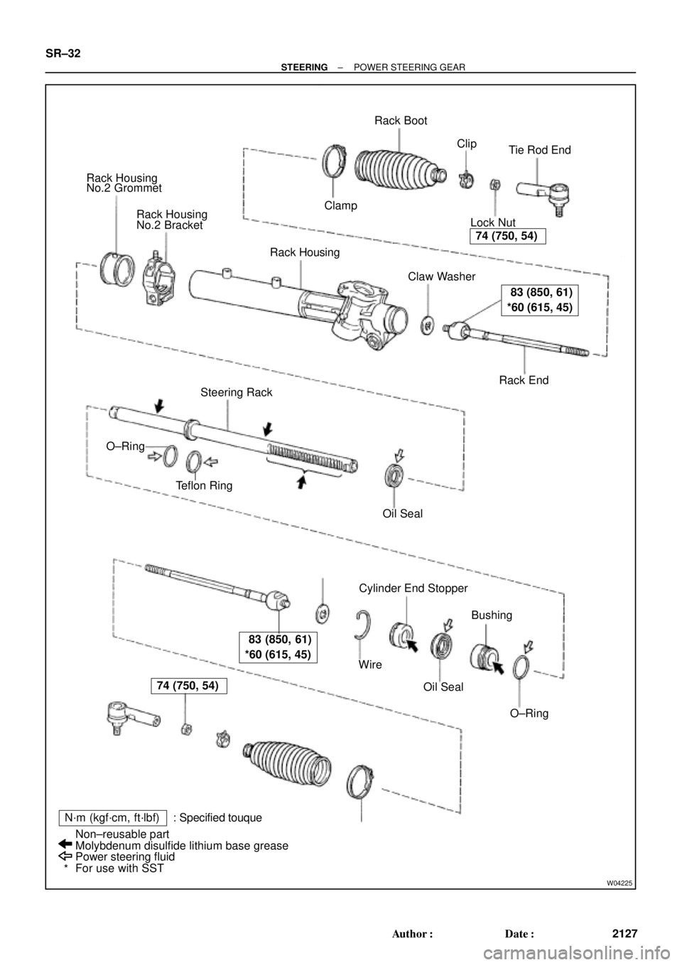
W04225
Rack Housing
No.2 Grommet
Rack Housing
No.2 Bracket
Rack Housing
� Claw Washer
Rack End Lock NutTie Rod End Rack Boot
� ClampClip
Steering Rack
� Teflon Ring
� Oil Seal
Cylinder End Stopper
Bushing
� O±Ring � Oil Seal � Wire �
�
N´m (kgf´cm, ft´lbf) : Specified touque
Power steering fluid
For use with SST Non±reusable part
Molybdenum disulfide lithium base grease �
*
74 (750, 54)
83 (850, 61)
*60 (615, 45)
83 (850, 61)
*60 (615, 45)
74 (750, 54)
� O±Ring SR±32
± STEERINGPOWER STEERING GEAR
2127 Author�: Date�:
Page 3541 of 4592
SR06V±01
W04228
SST
W04229
SST
R00429
Matchmarks
W04230
R11644
Claw Washer
± STEERINGPOWER STEERING GEAR
SR±35
2130 Author�: Date�:
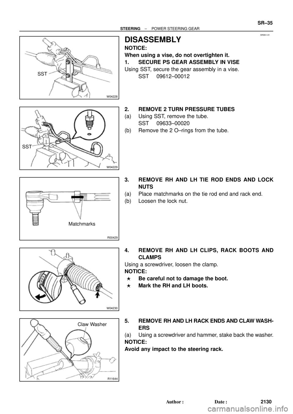
DISASSEMBLY
NOTICE:
When using a vise, do not overtighten it.
1. SECURE PS GEAR ASSEMBLY IN VISE
Using SST, secure the gear assembly in a vise.
SST 09612±00012
2. REMOVE 2 TURN PRESSURE TUBES
(a) Using SST, remove the tube.
SST 09633±00020
(b) Remove the 2 O±rings from the tube.
3. REMOVE RH AND LH TIE ROD ENDS AND LOCK
NUTS
(a) Place matchmarks on the tie rod end and rack end.
(b) Loosen the lock nut.
4. REMOVE RH AND LH CLIPS, RACK BOOTS AND
CLAMPS
Using a screwdriver, loosen the clamp.
NOTICE:
�Be careful not to damage the boot.
�Mark the RH and LH boots.
5. REMOVE RH AND LH RACK ENDS AND CLAW WASH-
ERS
(a) Using a screwdriver and hammer, stake back the washer.
NOTICE:
Avoid any impact to the steering rack.
Page 3554 of 4592

or less
SST
W04231
Fulcrum
LengthSST SR±48
± STEERINGPOWER STEERING GEAR
2143 Author�: Date�:
18. INSTALL RH AND LH RACK BOOTS, CLAMPS AND
CLIPS
(a) Ensure that the ste")
R11669
W04223
2 mm
(0.79 in.)
or less
SST
W04231
Fulcrum
LengthSST SR±48
± STEERINGPOWER STEERING GEAR
2143 Author�: Date�:
18. INSTALL RH AND LH RACK BOOTS, CLAMPS AND
CLIPS
(a) Ensure that the steering rack hole is not clogged with
grease.
HINT:
If the hole is clogged, the pressure inside the boot will change
after it is assembled and the steering wheel is turned.
(b) Install the boot.
NOTICE:
Be careful not to damage or twist the boot.
(c) Using SST, tighten the clamp as shown in the illustration.
SST 09521±24010
19. INSTALL RH AND LH TIE ROD ENDS AND LOCK NUTS
(a) Screw the lock nut and tie rod end onto the rack end until
the matchmarks are aligned.
(b) After adjusting toe±in, torque the nut.
(See page SA±4)
Torque: 74 N´m (750 kgf´cm, 54 ft´lbf)
20. INSTALL 2 TURN PRESSURE TUBES
(a) Coat 2 new O±rings with power steering fluid and install
them to the tube.
(b) Using SST, install the tube.
SST 09633±00020
Torque: 10 N´m (102 kgf´cm, 7 ft´lbf)
HINT:
�Use a torque wrench with a fulcrum length of 250 mm
(9.84 in.).
�This torque value is effective in case that SST is parallel
to a torque wrench.
Page 3562 of 4592
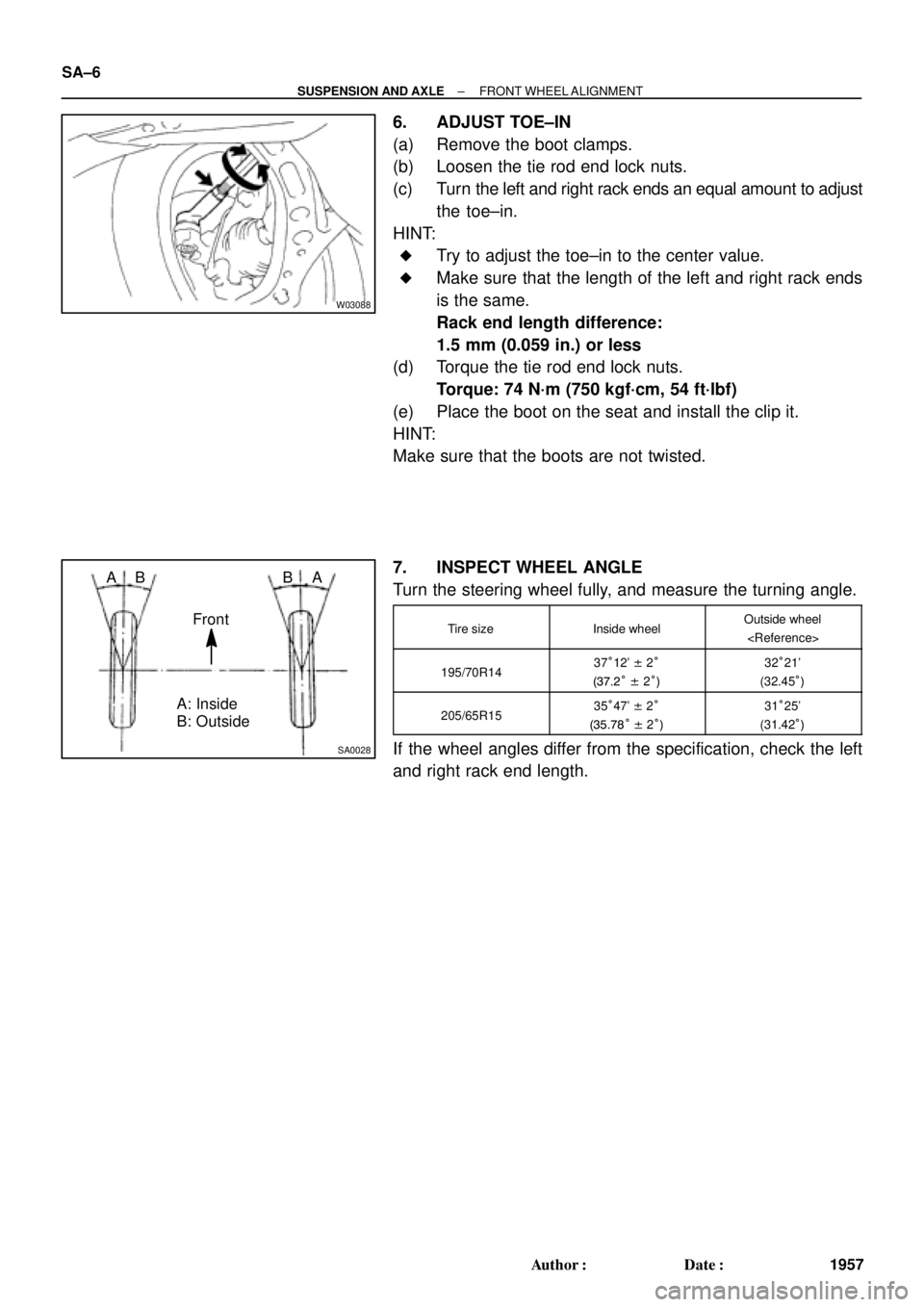
W03088
SA0028
A: Inside
B: Outside AB
Front BA SA±6
± SUSPENSION AND AXLEFRONT WHEEL ALIGNMENT
1957 Author�: Date�:
6. ADJUST TOE±IN
(a) Remove the boot clamps.
(b) Loosen the tie rod end lock nuts.
(c) Turn the left and right rack ends an equal amount to adjust
the toe±in.
HINT:
�Try to adjust the toe±in to the center value.
�Make sure that the length of the left and right rack ends
is the same.
Rack end length difference:
1.5 mm (0.059 in.) or less
(d) Torque the tie rod end lock nuts.
Torque: 74 N´m (750 kgf´cm, 54 ft´lbf)
(e) Place the boot on the seat and install the clip it.
HINT:
Make sure that the boots are not twisted.
7. INSPECT WHEEL ANGLE
Turn the steering wheel fully, and measure the turning angle.
Tire sizeInside wheelOutside wheel
195/70R1437°12' ± 2°
(37.2° ± 2°)32°21'
(32.45°)
205/65R1535°47' ± 2°
(35.78° ± 2°)31°25'
(31.42°)
If the wheel angles differ from the specification, check the left
and right rack end length.
Page 3572 of 4592
SA08P±01
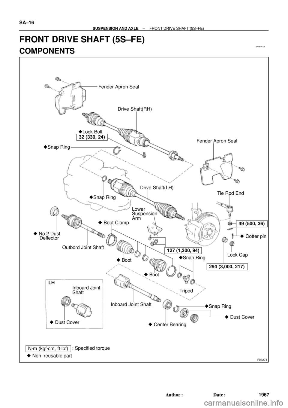
F03274
Fender Apron Seal
Drive Shaft(RH)
Fender Apron Seal �Lock Bolt
�Snap Ring
Tie Rod End
Lower
Suspension
Arm
� Boot Clamp
Outbord Joint Shaft � No.2 Dust
Deflector�Snap RingDrive Shaft(LH)
�Snap Ring
�Snap Ring � Boot
� Boot
294 (3,000, 217)� Cotter pin
Lock Cap
Tripod
� Dust Cover
� Center Bearing Inboard Joint Shaft Shaft Inboard Joint
� Dust Cover LH
N´m (kgf´cm, ft´lbf): Specified torque
� Non±reusable part
49 (500, 36)
127 (1,300, 94)
32 (330, 24)
SA±16
± SUSPENSION AND AXLEFRONT DRIVE SHAFT (5S±FE)
1967 Author�: Date�:
FRONT DRIVE SHAFT (5S±FE)
COMPONENTS
Page 3573 of 4592

SA±17
1968 Author�: Date�:
REMOVAL
NOTICE:
The hub bearing could be damaged if it is subjected to the
vehicle weig")
SA08Q±01
FA1535
SST
W03093
W03142
± SUSPENSION AND AXLEFRONT DRIVE SHAFT (5S±FE)
SA±17
1968 Author�: Date�:
REMOVAL
NOTICE:
The hub bearing could be damaged if it is subjected to the
vehicle weight, such as when moving the vehicle with the
drive shaft removed.
Therefore, if it is absolutely necessary to place the vehicle
weight on the hub bearing, first support it with SST.
SST 09608±16042 (09608±02021, 09608±02041)
1. REMOVE FRONT WHEEL AND FRONT FENDER
APRON SEAL
Torque: 103 N´m (1,050 kgf´cm, 76 ft´lbf)
2. REMOVE DRIVE SHAFT LOCK NUT
(a) Remove the cotter pin and lock cap.
(b) With applying the brakes, remove the nut.
Torque: 294 N´m (3,000 kgf´cm, 217 ft´lbf)
3. DRAIN GEAR OIL (M/T) or ATF (A/T)
4. DISCONNECT TIE ROD END FROM STEERING
KNUCKLE (See page SA±10)
5. DISCONNECT LOWER BALL JOINT FROM LOWER
SUSPENSION ARM (See page SA±10)
6. DISCONNECT DRIVE SHAFT FROM AXLE HUB
(a) Using a plastic hammer, disconnect the drive shaft from
the axle hub.
NOTICE:
Cover the drive shaft boot with cloth to protect it from dam-
age.
(b) Push the front axle hub toward the outside of the vehicle,
and separate the drive shaft from the axle hub.