Page 1124 of 4592
CL038±01
Q10083
Q05039
CL±6
± CLUTCHCLUTCH MASTER CYLINDER
1785 Author�: Date�:
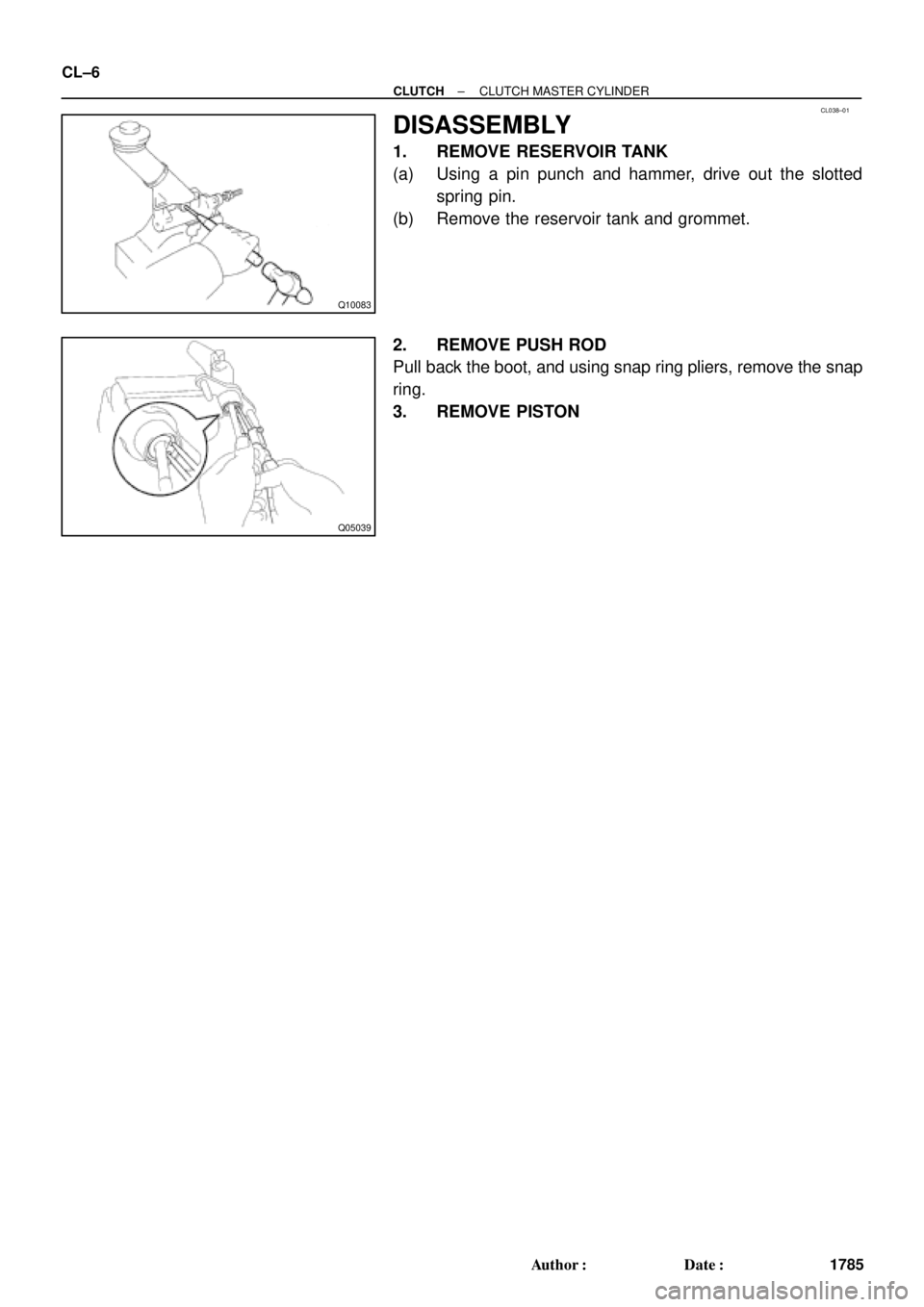
DISASSEMBLY
1. REMOVE RESERVOIR TANK
(a) Using a pin punch and hammer, drive out the slotted
spring pin.
(b) Remove the reservoir tank and grommet.
2. REMOVE PUSH ROD
Pull back the boot, and using snap ring pliers, remove the snap
ring.
3. REMOVE PISTON
Page 1127 of 4592
CL03B±01
Q10016
Clutch Line
15 (155, 11)
12 (120, 9)
Bleeder Plug
8.4 (85, 74 in.´lbf)
Release Cylinder Body
Piston
Spring
Push RodBoot
N´m (kgf´cm, ft´lbf)
: Specified torque
± CLUTCHCLUTCH RELEASE CYLINDER
CL±9
1788 Author�: Date�:
CLUTCH RELEASE CYLINDER
COMPONENTS
Page 1129 of 4592
CL03D±01
Q05878
± CLUTCHCLUTCH RELEASE CYLINDER
CL±11
1790 Author�: Date�:
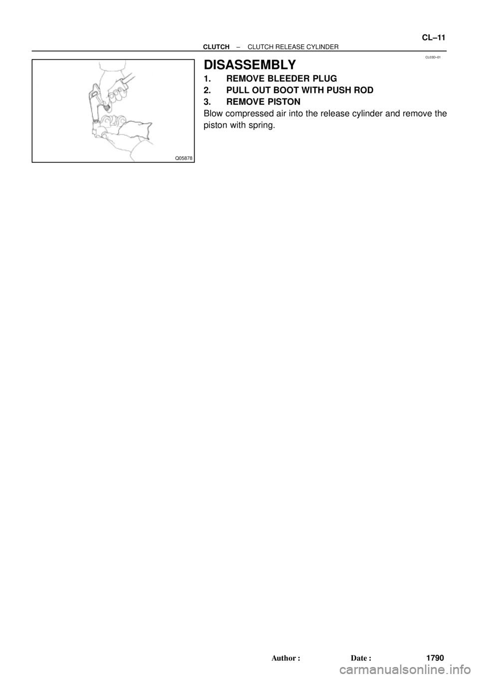
DISASSEMBLY
1. REMOVE BLEEDER PLUG
2. PULL OUT BOOT WITH PUSH ROD
3. REMOVE PISTON
Blow compressed air into the release cylinder and remove the
piston with spring.
Page 1130 of 4592
CL03E±01
Q06048
CL±12
± CLUTCHCLUTCH RELEASE CYLINDER
1791 Author�: Date�:
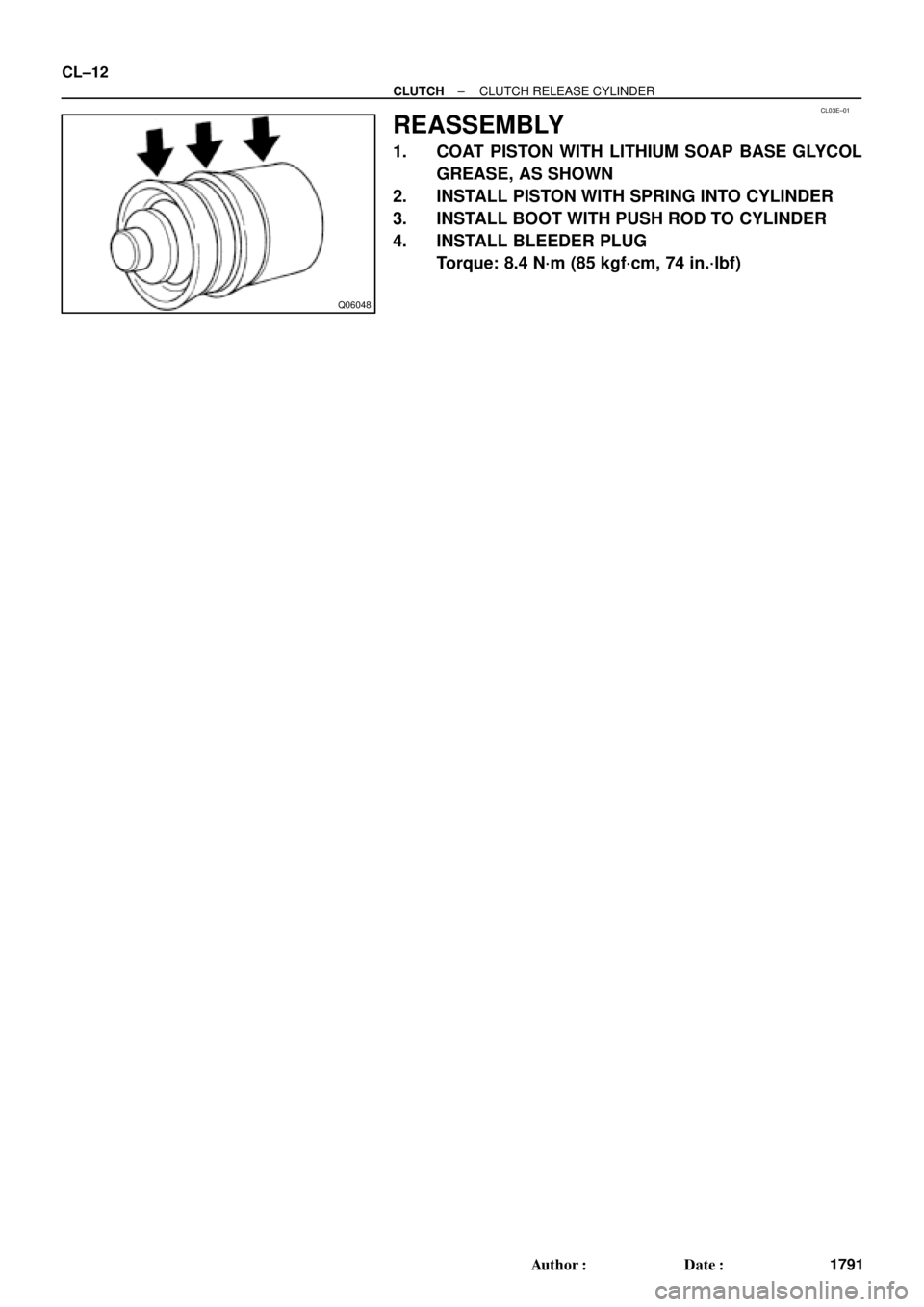
REASSEMBLY
1. COAT PISTON WITH LITHIUM SOAP BASE GLYCOL
GREASE, AS SHOWN
2. INSTALL PISTON WITH SPRING INTO CYLINDER
3. INSTALL BOOT WITH PUSH ROD TO CYLINDER
4. INSTALL BLEEDER PLUG
Torque: 8.4 N´m (85 kgf´cm, 74 in.´lbf)
Page 1135 of 4592
CL03J±01
Q10017
Flywheel
Clutch Disc
19 (195, 14)
47 (480, 35)
Clutch Coverx 6
Release Bearing and Hub
Release Fork5S±FE :
Release Fork
39 (400, 29)
5S±FE :
Clutch Disc
N´m (kgf´cm, ft´lbf) : Specified torqueBoot
± CLUTCHCLUTCH UNIT
CL±17
1796 Author�: Date�:
CLUTCH UNIT
COMPONENTS
Page 1136 of 4592
CL03K±01
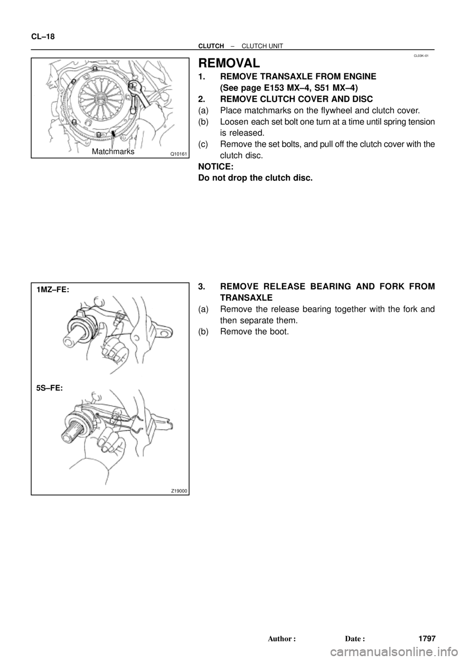
Q10161Matchmarks
Z19000
1MZ±FE:
5S±FE: CL±18
± CLUTCHCLUTCH UNIT
1797 Author�: Date�:
REMOVAL
1. REMOVE TRANSAXLE FROM ENGINE
(See page E153 MX±4, S51 MX±4)
2. REMOVE CLUTCH COVER AND DISC
(a) Place matchmarks on the flywheel and clutch cover.
(b) Loosen each set bolt one turn at a time until spring tension
is released.
(c) Remove the set bolts, and pull off the clutch cover with the
clutch disc.
NOTICE:
Do not drop the clutch disc.
3. REMOVE RELEASE BEARING AND FORK FROM
TRANSAXLE
(a) Remove the release bearing together with the fork and
then separate them.
(b) Remove the boot.
Page 1178 of 4592
B06388
No.2 Timing Belt CoverTiming Belt
Gasket
Timing Belt Guide
No.2 Generator
Bracket RH Engine Mounting Bracket
Crankshaft
PulleyGasket
Engine Wire Protector
RH Camshaft Timing PulleyNo.2 Idler Pulley
Dust Boot
Timing Belt Tensioner
� Non±reusable part
*For use with SSTNo.1 Timing Belt Cover
LH Camshaft
Timing Pulley
N´m (kgf´cm, ft´lbf) : Specified torque
28 (290, 21)
215 (2,200, 159)
125 (1,300, 94)*88 (900, 65)
43 (440, 32)
27 (280, 20)
125 (1,300, 94)
CO±4
± COOLING (1MZ±FE)WATER PUMP
1612 Author�: Date�:
Page 2679 of 4592
B06384
No.2 Timing Belt CoverTiming Belt
Gasket
Timing Belt Guide
No.2 Generator
Bracket RH Engine Mounting Bracket
Crankshaft
PulleyGasket
Engine Wire
Protector
RH Camshaft Timing Pulley
No.2 Idler Pulley
Crankshaft
Timing PulleyDust Boot
Timing Belt Plate Plate Washer
�
Timing Belt Tensioner
N´m (kgf´cm, ft´lbf)
: Specified torque
� Non±reusable part No.1 Timing Belt Cover
LH Camshaft
Timing Pulley
No.1 Idler Pulley
� Precoated part
* For use with SST
28 (290, 21)
215 (2,200, 159)
125 (1,300, 94)*88 (900, 65)43 (440, 32)
34 (350, 25)
27 (280, 20)
125 (1,300, 94)
EM±14
± ENGINE MECHANICAL (1MZ±FE)TIMING BELT
1300 Author�: Date�:

12 (120, 9)
Bleeder Plug
8.4 (85, 74 in.´lbf)
Release Cylinder Body
Piston
Spring
Push RodBoot
N´m (kgf´cm, ft´lbf)
: Specified torque
± CLUTCHCLUTCH REL")

47 (480, 35)
Clutch Coverx 6
Release Bearing and Hub
Release Fork5S±FE :
Release Fork
39 (400, 29)
5S±FE :
Clutch Disc
N´m (kgf´cm, ft´lbf) : Sp")