Page 3633 of 4592
SA08P±02
F03274
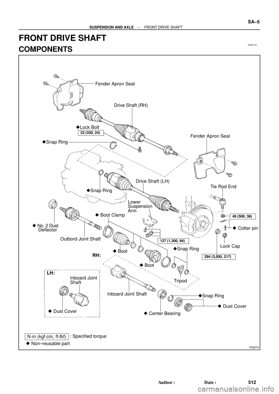
Fender Apron Seal
Drive Shaft (RH)
Fender Apron Seal �Lock Bolt
�Snap Ring
Tie Rod End
Lower
Suspension
Arm
� Boot Clamp
Outbord Joint Shaft � No. 2 Dust
Deflector�Snap RingDrive Shaft (LH)
�Snap Ring
�Snap Ring � Boot
� Boot� Cotter pin
Lock Cap
Tripod
� Dust Cover
� Center Bearing Inboard Joint Shaft Shaft Inboard Joint
� Dust Cover LH:
N´m (kgf´cm, ft´lbf): Specified torque
� Non±reusable part
32 (330, 24)
49 (500, 36)
294 (3,000, 217)
127 (1,300, 94)
RH:
± SUSPENSION AND AXLEFRONT DRIVE SHAFT
SA±5
512 Author�: Date�:
FRONT DRIVE SHAFT
COMPONENTS
Page 3635 of 4592
W03142
R00647
LH:
W03144
RH:
± SUSPENSION AND AXLEFRONT DRIVE SHAFT
SA±7
6. DISCONNECT DRIVE SHAFT FROM AXLE HUB
(a) Using a plastic hammer, disconnect the drive shaft from
the axle hub.
NOTICE:
Be careful not to damage the boot and ABS speed sensor
rotor.
(b) Push the front axle hub toward the outside of the vehicle,
and separate the drive shaft from the axle hub.
7. REMOVE LH DRIVE SHAFT
(a) Using a hub nut wrench and wooden block or an equiva-
lent, remove the drive shaft.
(b) Using a screwdriver, remove the snap ring from the in-
board joint shaft.
NOTICE:
Be careful not to damage the boot and ABS speed sensor
rotor.
8. REMOVE RH DRIVE SHAFT
(a) Remove the bearing lock bolt.
(b) Using pliers, remove the snap ring and drive shaft.
NOTICE:
Be careful not to damage the boot and ABS speed sensor
rotor.
Page 3636 of 4592
 Check to see that there is no remarkable play in the o")
SA1EA±02
N00191
F06526
BA
FA1615
Matchmarks
SA1443
Matchmarks
SA±8
± SUSPENSION AND AXLEFRONT DRIVE SHAFT
DISASSEMBLY
1. CHECK DRIVE SHAFT
(a) Check to see that there is no remarkable play in the out-
board joint.
(b) Check to see that the inboard joint slides smoothly in the
thrust direction.
(c) Check to see that there is no remarkable play in the radial
direction of the inboard joint.
(d) Check the boots for damage.
2. REMOVE INBOARD AND OUTBOARD JOINT BOOT
CLAMPS
(a) Using pliers, pinch the claw A and B to compress the large
inboard joint boot clamp and remove it.
(b) Using a side cutter, cut the small inboard joint boot clamp
and remove it.
(c) Using a side cutter, cut the 2 outboard joint boot clamps
and remove them.
3. REMOVE INBOARD JOINT SHAFT
(a) Place matchmarks on the tripod, inboard and outboard
joint shafts.
NOTICE:
Do not punch the marks.
(b) Remove the inboard joint shaft from the outboard joint
shaft.
4. REMOVE TRIPOD
(a) Using a snap ring expander, remove the inboard joint side
snap ring.
(b) Using a snap ring expander, temporarily slide the out-
board joint side snap ring toward the outboard joint side.
(c) Place matchmarks on the outboard joint shaft and tripod.
NOTICE:
Do not punch the marks.
(d) Using a brass bar and hammer, remove the tripod from
the outboard joint shaft.
NOTICE:
Do not tap the roller.
(e) Using a snap ring expander, remove the snap ring.
Page 3637 of 4592
R09716
SST
SA1446
R09717
SST
SA1451
± SUSPENSION AND AXLEFRONT DRIVE SHAFT
SA±9
5. REMOVE INBOARD AND OUTBOARD JOINT BOOTS
Slide out the 2 boots.
NOTICE:
Do not disassemble the outboard joint.
6. LH drive shaft:
REMOVE DUST COVER
Using SST and a press, remove the dust cover from the inboard
joint shaft.
SST 09950±00020
7. RH drive shaft:
DISASSEMBLE INBOARD JOINT SHAFT
(a) Using a press, remove the transaxle side dust cover from
the inboard joint shaft.
(b) Using SST and a press, remove the bearing side dust
cover.
SST 09950±00020
(c) Using a snap ring expander, remove the snap ring.
(d) Using a press, remove the bearing.
(e) Remove the snap ring.
Page 3640 of 4592

F01747
Inboard Joint BootOutboard Joint Boot
Vinyl tape
R00764
SA±12
± SUSPENSION AND AXLEFRONT DRIVE SHAFT
4. TEMPORARILY INSTALL OUTBOARD AND INBOARD
JOINT BOOTS AND NEW BOOT CLAMPS
HINT:
�Before installing the boots, wrap the spline of the out-
board joint shaft with vinyl tape to prevent the boots from
being damaged.
�Before installing the boots, place 3 new clamps to the
small boot ends and large boot end (outboard joint side).
5. INSTALL TRIPOD
(a) Using a snap ring expander, install a new snap ring.
(b) Place the beveled side of the tripod axial spline toward the
outboard joint.
(c) Align the matchmarks placed before removal.
(d) Using a brass bar and hammer, tap in the tripod to the out-
board joint shaft.
NOTICE:
Do not tap the roller.
(e) Using a snap ring expander, install a new snap ring.
6. INSTALL BOOT TO OUTBOARD JOINT
Before assembling the boot, pack the outboard joint and boot
with grease in the boot kit.
Grease capacity (Color = Black):
100 ± 120 g (3.5 ± 4.2 oz.)
7. INSTALL INBOARD JOINT SHAFT TO OUTBOARD
JOINT SHAFT
(a) Pack the inboard joint and boot with grease in the boot kit.
Grease capacity (Color = Yellow ocher):
125 ± 155 g (4.4 ± 5.5 oz.)
(b) Align the matchmarks placed before removal, and install
the inboard joint shaft to the outboard joint shaft.
(c) Temporarily install the boot to the inboard joint shaft.
8. CHECK DRIVE SHAFT LENGTH
(a) Make sure that the 2 boots are on the shaft groove.
(b) Make sure that the 2 boots are not stretched or contracted
when the drive shaft is at standard length.
Drive shaft standard length:
LH609.2 ± 2.0 mm (23.984 ± 0.079 in.)
RH842.9 ± 2.0 mm (33.185 ± 0.079 in.)
Page 3641 of 4592
F06527
C
B
C'
A
R10353
SST
F00616
Clearance
SST
ABC
± SUSPENSION AND AXLEFRONT DRIVE SHAFT
SA±13
9. Large inboard joint boot clamp:
INSTALL BOOT CLAMP TO INBOARD JOINT SHAFT
BOOT
(a) Place the large inboard joint boot clamp.
(b) Using pliers, pinch the claw A and B to compress the
clamp and engage the claw C and C'.
10. Others:
INSTALL BOOT CLAMPS TO BOTH BOOTS
(a) Secure the preplaced 3 clamps onto the boots.
(b) Place SST onto the clamp.
SST 09521±24010
(c) Tighten the SST so that the clamp is pinched.
NOTICE:
Do not overtighten the SST.
(d) Using SST, adjust the clearance of the clamp.
SST 09240±00020
Clearance:
A : 1.9 mm (0.075 in.) or less
B : 1.5 ± 2.5 mm (0.059 ± 0.098 in.)
C : 3.0 ± 4.0 mm (0.118 ± 0.157 in.)
11. CHECK DRIVE SHAFT (See page SA±8)
Page 3642 of 4592
 Install a new snap ring to the inboard joint shaft.
(b) Coat the gear oil")
SA1EC±02
SA±14
± SUSPENSION AND AXLEFRONT DRIVE SHAFT
INSTALLATION
1. LH drive shaft:
INSTALL DRIVE SHAFT TO TRANSAXLE
(a) Install a new snap ring to the inboard joint shaft.
(b) Coat the gear oil to the inboard joint shaft and differential case sliding surface.
(c) Set the snap ring with opening side facing downward.
(d) Using a brass bar and hammer, install the drive shaft.
NOTICE:
Be careful not to damage the dust cover of the drive shaft and oil seal lip of the transaxle.
HINT:
Whether the inboard joint shaft is in contact with the pinion shaft or not can be known from the sound or feel-
ing when driving it in.
(e) Check that there is 2 ± 3 mm (0.08 ± 0.12 in.) of play in the axial direction.
(f) Check that the drive shaft cannot be removed by hand.
2. RH drive shaft:
INSTALL DRIVE SHAFT TO TRANSAXLE
(a) Install the drive shaft.
NOTICE:
Be careful not to damage the dust cover of the drive shaft and oil seal lip of the transaxle.
(b) Using pliers, install a new snap ring.
(c) Install a new bearing lock bolt.
Torque: 32 N´m (330 kgf´cm, 24 ft´lbf)
3. CONNECT DRIVE SHAFT TO AXLE HUB
NOTICE:
Be careful not to damage the boot and ABS speed sensor rotor.
4. CONNECT LOWER SUSPENSION ARM TO LOWER BALL JOINT
Torque: 127 N´m (1,300 kgf´cm, 94 ft´lbf)
5. CONNECT TIE ROD END TO STEERING KNUCKLE
(a) Connect the tie rod end to the steering knuckle.
(b) Install the nut and a new cotter pin.
If the holes for the cotter pin are not aligned, tighten the nut further up to 60°.
Torque: 49 N´m (500 kgf´cm, 36 ft´lbf)
6. INSTALL DRIVE SHAFT LOCK NUT
(a) While applying brakes, install the nut.
Torque: 294 N´m (3,000 kgf´cm, 217 ft´lbf)
(b) Install the lock cap and a new cotter pin.
If the holes for the cotter pin are not aligned, tighten the nut further up to 60°.
7. FILL AND CHECK ATF (See page DI±133)
8. INSTALL FRONT FENDER APRON SEAL
9. INSTALL FRONT WHEEL
Torque: 103 N´m (1,050 kgf´cm, 76 ft´lbf)
10. CHECK FRONT WHEEL ALIGNMENT (See page SA±1)
11. CHECK ABS SPEED SENSOR SIGNAL (See page DI±177)
Page 3898 of 4592

SUSPENSION BALL JOINT INSPECTION ± PG027-02December 4, 2002
Page 7 of 8
2. Inspect Upper Ball Joint Free Play
A. Move the upper arm by hand
(models with the LOWER control
arm linked by a torsion bar, and
all models using a coil spring).
a. Remove the front tire.
b. Inspect the free play while
moving the upper arm up and
down at a force of 67 lbf
(294 N, 30 kgf).
B. Move the tire with a lever (models
with the UPPER control arm
linked by a torsion bar).
a. Lift up the vehicle.
b. Place the lever under the tire,
and inspect the free play while
lifting the tire using a wooden
stick, etc., as a fulcrum.
3. Inspect the Suspension Arm Ball
Joint Free Play
A. Lift up the vehicle.
B. Inspect the free play while moving
the control arm by hand.
(Reference)
Free Play Inspection Method
(Gauge Installation)
�Position the dial gauge between the
arm (upper or lower) and the knuckle,
and measure free play.
(This illustration shows how to
measure free play for vehicles with
double wishbone type suspension
with coil spring.)
4. Inspect Ball Joint Dust Cover
Check for cracks and grease leaks on
the dust cover (boots).On±Vehicle
Inspection
(Continued)
 Using a plastic hammer, disconnect the drive shaft from
the axle hub.
NOTICE:
Be")

 Place the large")