Page 2962 of 4592
INPUT SHAFT
MX±29
1830 Author�: Date�:
REASSEMBLY
HINT:
Coat all of the sliding and rotating surfaces with gear oil before
rea")
MX059±02
Q00383
Front
MT0790
Q00183SST
Q00116
± MANUAL TRANSAXLE (E153)INPUT SHAFT
MX±29
1830 Author�: Date�:
REASSEMBLY
HINT:
Coat all of the sliding and rotating surfaces with gear oil before
reassembly.
1. INSTALL NO.2 CLUTCH HUB INTO HUB SLEEVE
(a) Install the 3 springs and shifting keys to the clutch hub.
(b) Install the hub sleeve to the clutch hub.
HINT:
Direct identification groove of the hub sleeve to front of the
transmission.
2. INSTALL NEEDLE ROLLER BEARING, 3RD GEAR,
SYNCHRONIZER RING AND NO.2 HUB SLEEVE AS-
SEMBLY TO INPUT SHAFT
(a) Apply MP grease to the needle roller bearing.
(b) Assemble the needle roller bearings into the 3rd gear.
(c) Place the synchronizer rings on the gear and align the
ring slots with the shifting keys.
(d) Using SST and a press, install the 3rd gear and No.2 hub
sleeve.
SST 09506±35010
3. INSTALL SNAP RING
(a) Select a snap ring that allows the minimum axial play.
MarkThickness mm (in.)MarkThickness mm (in.)
H2.30 (0.0906)M2.50 (0.0984)
J2.35 (0.0925)N2.55 (0.1004)
K2.40 (0.0945)P2.60 (0.1024)
L2.45 (0.0965)±±
(b) Using a screwdriver and hammer, tap in the snap ring.
Page 2963 of 4592
N00494
SST
Q00116
MX±30
± MANUAL TRANSAXLE (E153)INPUT SHAFT
1831 Author�: Date�:
4. MEASURE 3RD GEAR THRUST CLEARANCE
(See page MX±24)
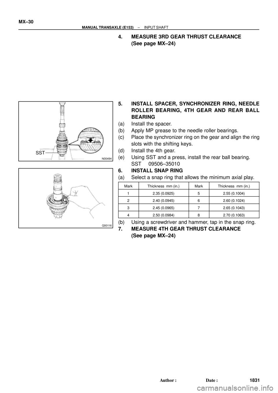
5. INSTALL SPACER, SYNCHRONIZER RING, NEEDLE
ROLLER BEARING, 4TH GEAR AND REAR BALL
BEARING
(a) Install the spacer.
(b) Apply MP grease to the needle roller bearings.
(c) Place the synchronizer ring on the gear and align the ring
slots with the shifting keys.
(d) Install the 4th gear.
(e) Using SST and a press, install the rear ball bearing.
SST 09506±35010
6. INSTALL SNAP RING
(a) Select a snap ring that allows the minimum axial play.
MarkThickness mm (in.)MarkThickness mm (in.)
12.35 (0.0925)52.55 (0.1004)
22.40 (0.0945)62.60 (0.1024)
32.45 (0.0965)72.65 (0.1043)
42.50 (0.0984)82.70 (0.1063)
(b) Using a screwdriver and hammer, tap in the snap ring.
7. MEASURE 4TH GEAR THRUST CLEARANCE
(See page MX±24)
Page 2964 of 4592
MX05A±01
N00785
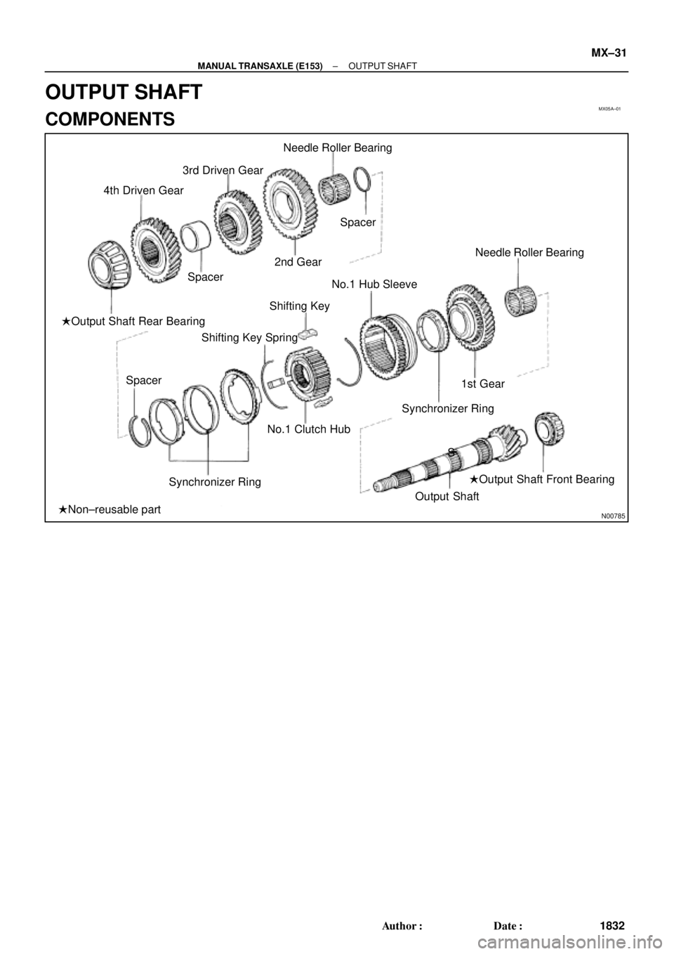
Needle Roller Bearing
Spacer
2nd Gear 3rd Driven Gear
Spacer 4th Driven Gear
�Output Shaft Rear Bearing
Spacer
Synchronizer RingNo.1 Clutch Hub Shifting Key Spring
S Shifting KeyNo.1 Hub Sleeve
Synchronizer Ring1st GearNeedle Roller Bearing
Output Shaft�Output Shaft Front Bearing
�Non±reusable part
± MANUAL TRANSAXLE (E153)OUTPUT SHAFT
MX±31
1832 Author�: Date�:
OUTPUT SHAFT
COMPONENTS
Page 2969 of 4592
OUTPUT SHAFT
1837 Author�: Date�:
REASSEMBLY
HINT:
Coat all of the sliding and rotating surfaces with gear oil before
r")
MX05D±01
Q00384
Front
Z00225
Z00385
SST
Z00386
MX±36
± MANUAL TRANSAXLE (E153)OUTPUT SHAFT
1837 Author�: Date�:
REASSEMBLY
HINT:
Coat all of the sliding and rotating surfaces with gear oil before
reassembly.
1. INSTALL NO.1 CLUTCH HUB INTO HUB SLEEVE
(a) Install the clutch hub and shifting keys to the hub sleeve.
(b) Install the shifting key springs under the shifting keys.
NOTICE:
Position the key springs so that their end gaps are not
aligned.
2. INSTALL NEEDLE ROLLER BEARING, 1ST GEAR,
SYNCHRONIZER RING AND NO.1 HUB SLEEVE TO
OUTPUT SHAFT
(a) Apply MP grease to the needle roller bearing.
(b) Install the 1st gear.
(c) Place the synchronizer ring (for the 1st gear) on the gear
and align the ring slots with the shifting keys.
(d) Using SST and a press, install the 1st gear and No.1 hub
sleeve.
SST 09316±60011 (09316±00041)
3. INSTALL SNAP RING
(a) Select a snap ring that allows the minimum axial play.
MarkThickness mm (in.)MarkThickness mm (in.)
A2.80 (0.1102)E3.00 (0.1181)
B2.85 (0.1122)F3.05 (0.1201)
C2.90 (0.1142)G3.10 (0.1220)
D2.95 (0.1161)±±
(b) Using a snap ring expander, install the snap ring.
Page 3002 of 4592
MX04J±01
Q02560
Synchronizer RingSpacer
Needle Roller Bearing
4th Gear
Snap Ring
Input Shaft
3rd Gear
No.2 Hub Sleeve
Key Spring Shifting Key Synchronizer Ring
Needle Roller BearingSnap Ring Rear Bearing
No.2 Clutch Hub
MX±20
± MANUAL TRANSAXLE (S51)INPUT SHAFT
1870 Author�: Date�:
INPUT SHAFT
COMPONENTS
Page 3004 of 4592
CM0064
SST
SM0269
MX±22
± MANUAL TRANSAXLE (S51)INPUT SHAFT
1872 Author�: Date�:
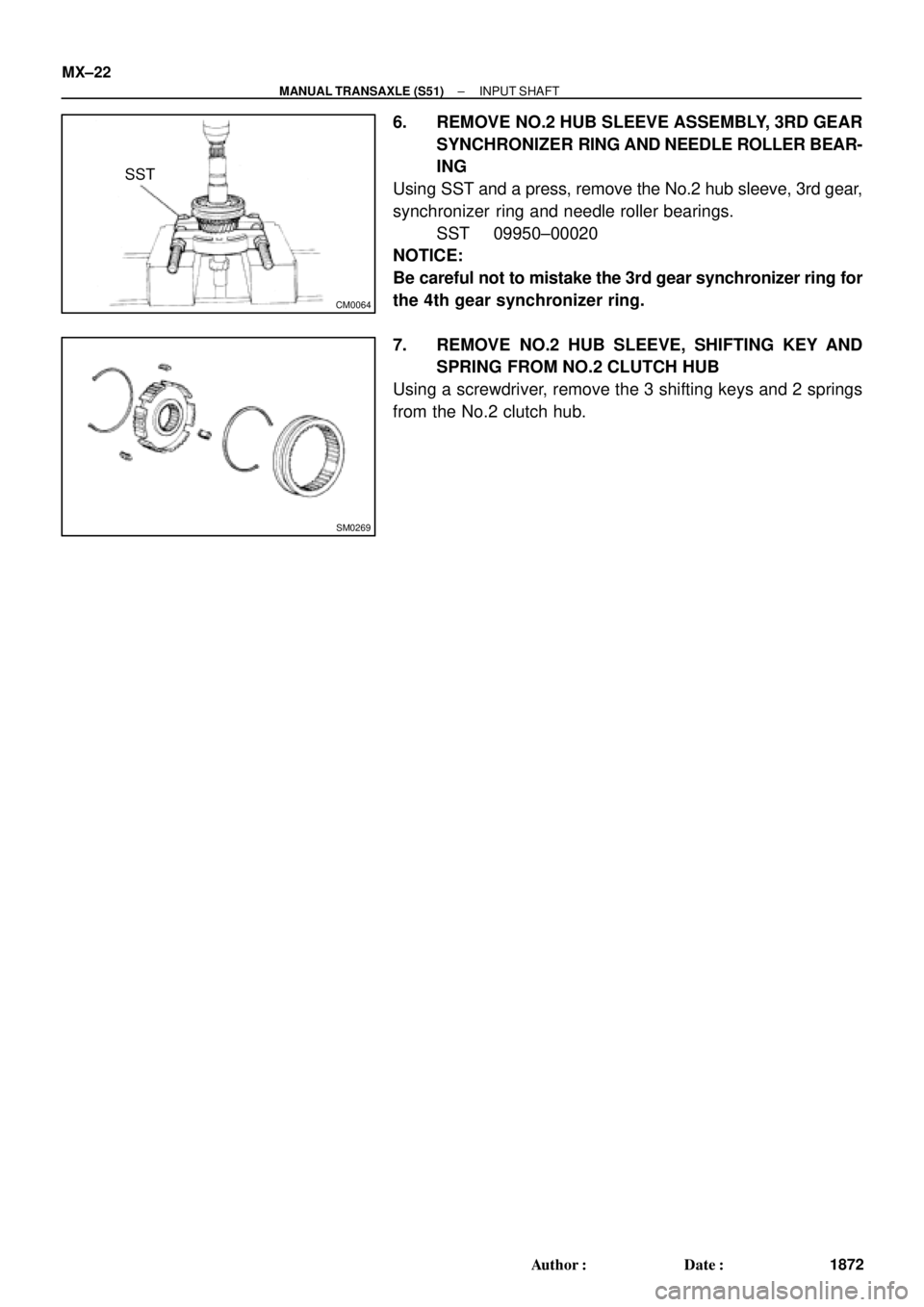
6. REMOVE NO.2 HUB SLEEVE ASSEMBLY, 3RD GEAR
SYNCHRONIZER RING AND NEEDLE ROLLER BEAR-
ING
Using SST and a press, remove the No.2 hub sleeve, 3rd gear,
synchronizer ring and needle roller bearings.
SST 09950±00020
NOTICE:
Be careful not to mistake the 3rd gear synchronizer ring for
the 4th gear synchronizer ring.
7. REMOVE NO.2 HUB SLEEVE, SHIFTING KEY AND
SPRING FROM NO.2 CLUTCH HUB
Using a screwdriver, remove the 3 shifting keys and 2 springs
from the No.2 clutch hub.
Page 3007 of 4592
INPUT SHAFT
MX±25
1875 Author�: Date�:
REASSEMBLY
HINT:
Coat all of the sliding and rotating surfaces with gear oil before
r")
MX04M±01
SM0282
Engine
Side
SM0193
Z00419
Z00604
± MANUAL TRANSAXLE (S51)INPUT SHAFT
MX±25
1875 Author�: Date�:
REASSEMBLY
HINT:
Coat all of the sliding and rotating surfaces with gear oil before
reassembly.
1. INSTALL NO.2 CLUTCH HUB INTO HUB SLEEVE
(a) Install the clutch hub and shifting keys to the hub sleeve.
(b) Install the shifting key springs under the shifting keys.
NOTICE:
Position the key springs so that their end gaps are not
aligned.
2. INSTALL 3RD GEAR, NEEDLE ROLLER BEARING,
SYNCHRONIZER RING AND NO.2 HUB SLEEVE AS-
SEMBLY TO INPUT SHAFT
(a) Apply gear oil to the needle roller bearings.
(b) Place the synchronizer ring (for the 3rd gear) on the gear
and align the ring slots with the shifting keys.
NOTICE:
Do not install the synchronizer ring for 4th gear.
(c) Using a press, install the 3rd gear and No.2 hub sleeve.
3. INSTALL SNAP RING
(a) Select a snap ring that allows the minimum axial play.
MarkThickness mm (in.)
11.95±2.00 (0.0768±0.0787)
22.00±2.05 (0.0787±0.0807)
32.05±2.10 (0.0807±0.0827)
42.10±2.15 (0.0827±0.0846)
52.15±2.20 (0.0846±0.0866)
62.20±2.25 (0.0866±0.0886)
Page 3008 of 4592
SM0189
SM0190
SM0049
SST
SM0050
MX±26
± MANUAL TRANSAXLE (S51)INPUT SHAFT
1876 Author�: Date�:
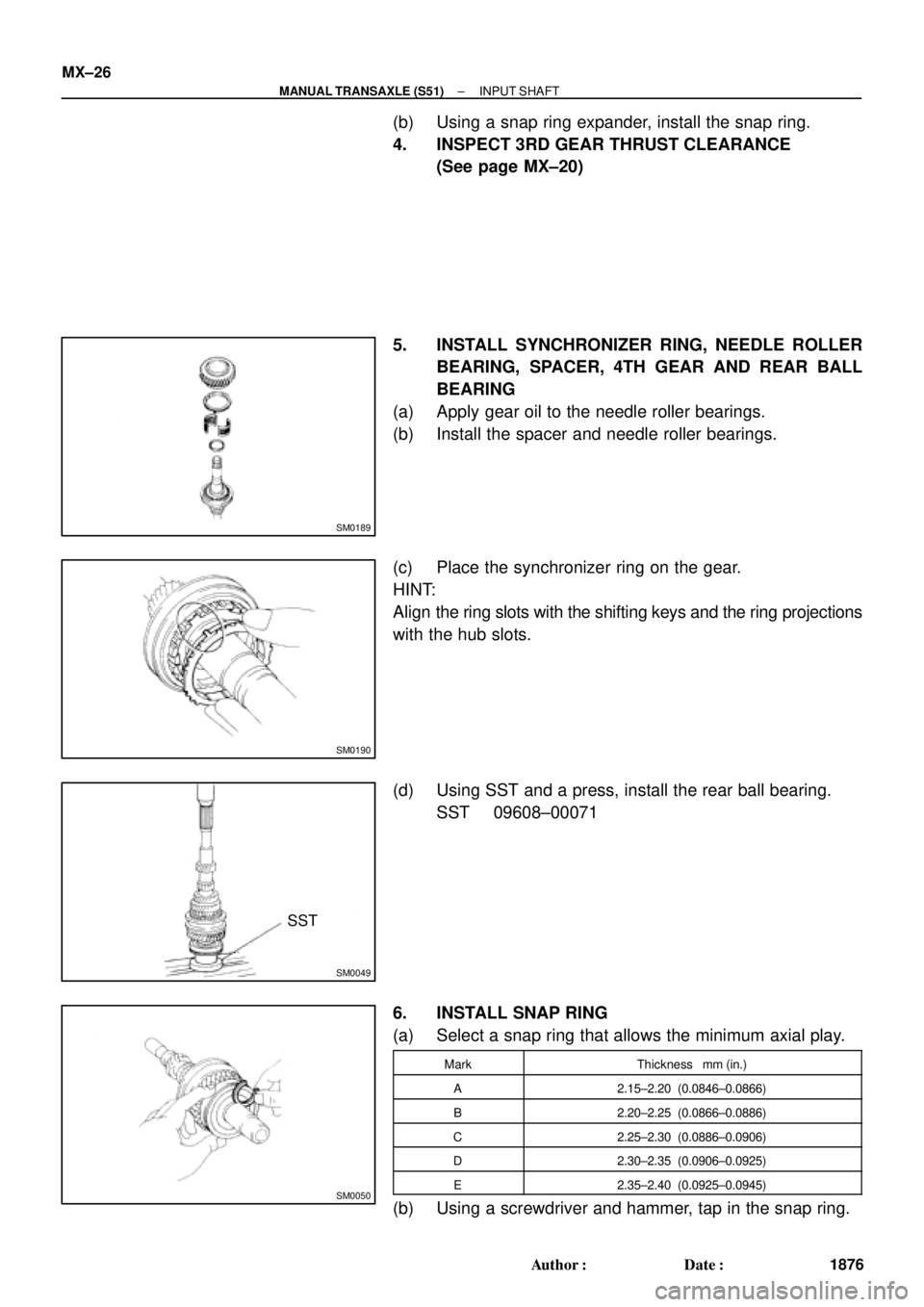
(b) Using a snap ring expander, install the snap ring.
4. INSPECT 3RD GEAR THRUST CLEARANCE
(See page MX±20)
5. INSTALL SYNCHRONIZER RING, NEEDLE ROLLER
BEARING, SPACER, 4TH GEAR AND REAR BALL
BEARING
(a) Apply gear oil to the needle roller bearings.
(b) Install the spacer and needle roller bearings.
(c) Place the synchronizer ring on the gear.
HINT:
Align the ring slots with the shifting keys and the ring projections
with the hub slots.
(d) Using SST and a press, install the rear ball bearing.
SST 09608±00071
6. INSTALL SNAP RING
(a) Select a snap ring that allows the minimum axial play.
MarkThickness mm (in.)
A2.15±2.20 (0.0846±0.0866)
B2.20±2.25 (0.0866±0.0886)
C2.25±2.30 (0.0886±0.0906)
D2.30±2.35 (0.0906±0.0925)
E2.35±2.40 (0.0925±0.0945)
(b) Using a screwdriver and hammer, tap in the snap ring.