Page 2323 of 4592
D05150
ECM
B+
OD2
(*) O/D Main
Switch Instrument
Panel J/BIgnition Switch
J5
Junction
Connector
B±RAM1
G±O
E47 IF1 11
G±O
G±O
O2 2
O2 4C
C
C
W±B
J4
Junction
Connector
W±B A
A
IE G±O IG1I104
I102
W
IK2
AM1
IB 1
B±R
F14 1
F14 2
ALT
F9 1
B±G
FL
MAINInstrument Panel
J/B
GAUGE
O/D OFF
Indicator Light
(Combination Meter)
FUSIBLE
LINK
BLOCK
O/D Main Switch
Contacts go open with switch pushed in
contacts go closed with switch pushed once again1K1
1D2
R±L
R±L
Battery J3
Junction
Connector
DDC127
C1012
*:
± DIAGNOSTICSAUTOMATIC TRANSAXLE
DI±171
O/D Main Switch & O/D OFF Indictor Light Circuit
CIRCUIT DESCRIPTION
The O/D main switch contacts go open when the switch is pushed in and go closed when it is pushed out.
In O/D main switch in OFF position, the O/D OFF indicator light lights up, and the ECM prohibits shifting over-
drive.
WIRING DIAGRAM
DI1J1±04
Page 2480 of 4592

DI08L±14
DI±328
± DIAGNOSTICSCRUISE CONTROL SYSTEM
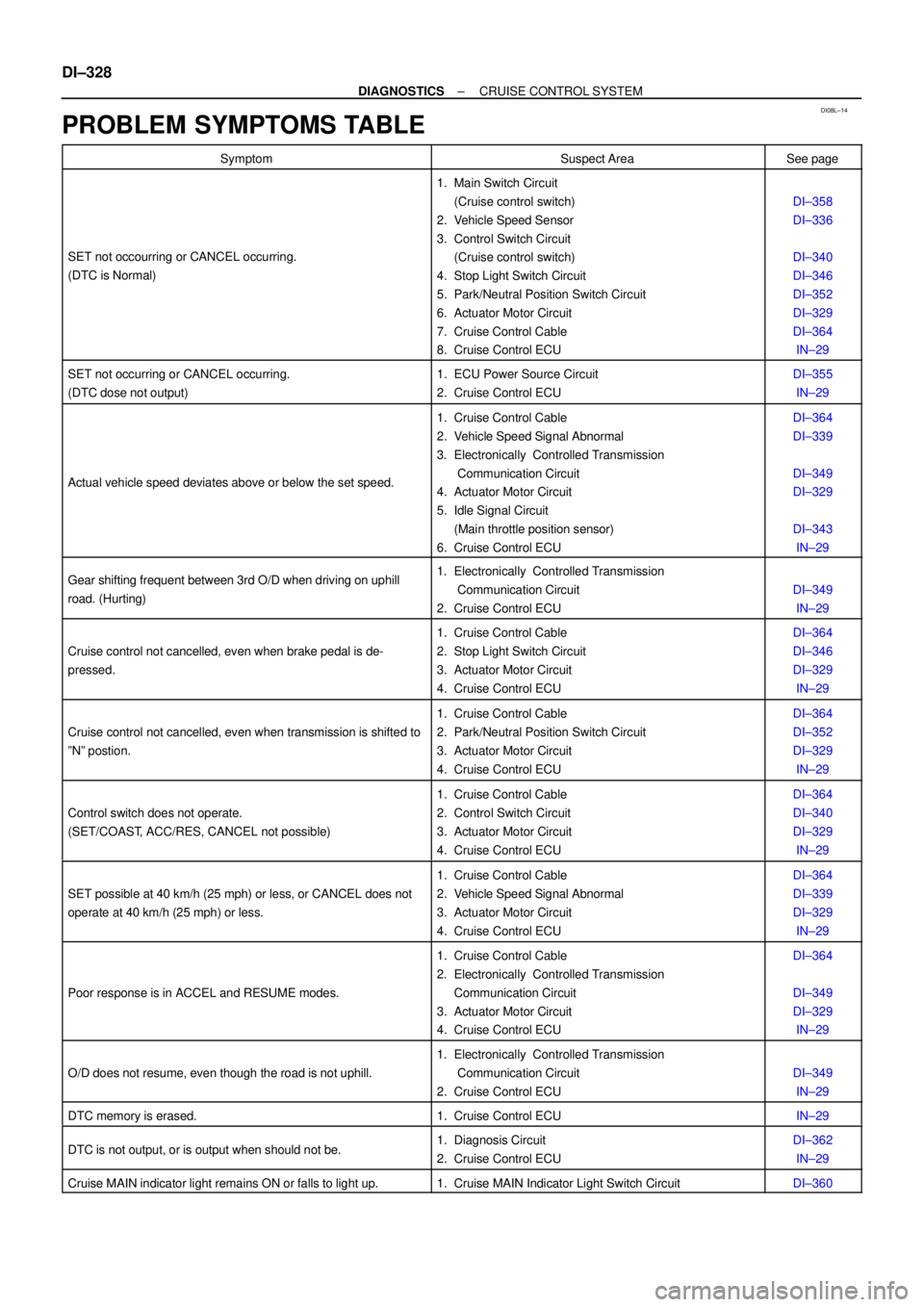
PROBLEM SYMPTOMS TABLE
SymptomSuspect AreaSee page
SET not occourring or CANCEL occurring.
(DTC is Normal)
1. Main Switch Circuit
(Cruise control switch)
2. Vehicle Speed Sensor
3. Control Switch Circuit
(Cruise control switch)
4. Stop Light Switch Circuit
5. Park/Neutral Position Switch Circuit
6. Actuator Motor Circuit
7. Cruise Control Cable
8. Cruise Control ECU
DI±358
DI±336
DI±340
DI±346
DI±352
DI±329
DI±364
IN±29
SET not occurring or CANCEL occurring.
(DTC dose not output)1. ECU Power Source Circuit
2. Cruise Control ECUDI±355
IN±29
Actual vehicle speed deviates above or below the set speed.
1. Cruise Control Cable
2. Vehicle Speed Signal Abnormal
3. Electronically Controlled Transmission
Communication Circuit
4. Actuator Motor Circuit
5. Idle Signal Circuit
(Main throttle position sensor)
6. Cruise Control ECUDI±364
DI±339
DI±349
DI±329
DI±343
IN±29
Gear shifting frequent between 3rd O/D when driving on uphill
road. (Hurting)1. Electronically Controlled Transmission
Communication Circuit
2. Cruise Control ECU
DI±349
IN±29
Cruise control not cancelled, even when brake pedal is de-
pressed.
1. Cruise Control Cable
2. Stop Light Switch Circuit
3. Actuator Motor Circuit
4. Cruise Control ECUDI±364
DI±346
DI±329
IN±29
Cruise control not cancelled, even when transmission is shifted to
ºNº postion.
1. Cruise Control Cable
2. Park/Neutral Position Switch Circuit
3. Actuator Motor Circuit
4. Cruise Control ECUDI±364
DI±352
DI±329
IN±29
Control switch does not operate.
(SET/COAST, ACC/RES, CANCEL not possible)
1. Cruise Control Cable
2. Control Switch Circuit
3. Actuator Motor Circuit
4. Cruise Control ECUDI±364
DI±340
DI±329
IN±29
SET possible at 40 km/h (25 mph) or less, or CANCEL does not
operate at 40 km/h (25 mph) or less.
1. Cruise Control Cable
2. Vehicle Speed Signal Abnormal
3. Actuator Motor Circuit
4. Cruise Control ECUDI±364
DI±339
DI±329
IN±29
Poor response is in ACCEL and RESUME modes.
1. Cruise Control Cable
2. Electronically Controlled Transmission
Communication Circuit
3. Actuator Motor Circuit
4. Cruise Control ECUDI±364
DI±349
DI±329
IN±29
O/D does not resume, even though the road is not uphill.
1. Electronically Controlled Transmission
Communication Circuit
2. Cruise Control ECU
DI±349
IN±29
DTC memory is erased.1. Cruise Control ECUIN±29
DTC is not output, or is output when should not be.1. Diagnosis Circuit
2. Cruise Control ECUDI±362
IN±29
Cruise MAIN indicator light remains ON or falls to light up.1. Cruise MAIN Indicator Light Switch CircuitDI±360
Page 2501 of 4592

I08462
ECM
OD120
E4
S26
E6L±BY±B
J19
J/C
B
L±BBCruise Control ECU
14
C16OD
ECT 7
IG2
ECT No.2
SolenoidL±B L±B6
C16
± DIAGNOSTICSCRUISE CONTROL SYSTEM
DI±349
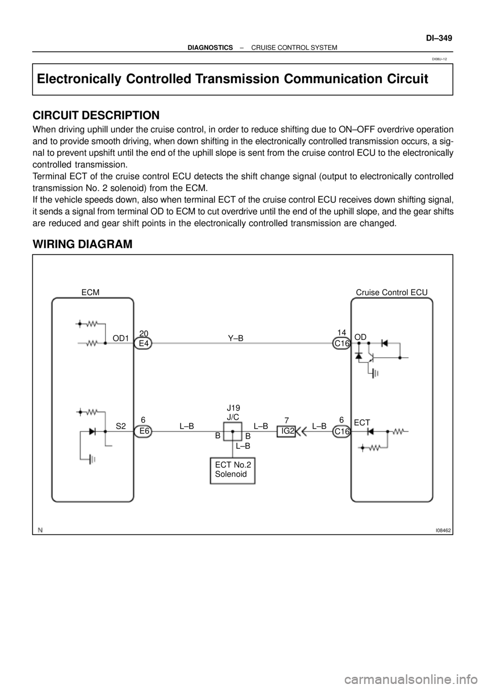
Electronically Controlled Transmission Communication Circuit
CIRCUIT DESCRIPTION
When driving uphill under the cruise control, in order to reduce shifting due to ON±OFF overdrive operation
and to provide smooth driving, when down shifting in the electronically controlled transmission occurs, a sig-
nal to prevent upshift until the end of the uphill slope is sent from the cruise control ECU to the electronically
controlled transmission.
Terminal ECT of the cruise control ECU detects the shift change signal (output to electronically controlled
transmission No. 2 solenoid) from the ECM.
If the vehicle speeds down, also when terminal ECT of the cruise control ECU receives down shifting signal,
it sends a signal from terminal OD to ECM to cut overdrive until the end of the uphill slope, and the gear shifts
are reduced and gear shift points in the electronically controlled transmission are changed.
WIRING DIAGRAM
DI08U±12
Page 2505 of 4592
Input SignalIndicator Light
Blinking Pattern
Turn PNP switch
OFF (Shift to posi-
tions except D )LightON
OFFSW ON
SW OFF
± DIAGNOSTICSCRUISE CONTROL SYSTEM
DI±353
INSPECTION PROCEDURE
1 Check starter operation.
CHECK:
Check that the starter operates normally and that the engine starts.
NG Proceed to engine troubleshooting
(See Pub. No. RM654U on page ST±1).
OK
2 Input signal check.
PREPARATION:
See input signal check on page DI±319.
CHECK:
Check the indicator light when shifting into positions except D.
OK:
The indicator light goes off when shifting into posi-
tions except D.
OK Proceed to next circuit inspection shown on
problem symptoms table (See page DI±328).
NG
Page 2506 of 4592
AB0119
I00139
I00175
ON
D
(±) (+)
DI±354
± DIAGNOSTICSCRUISE CONTROL SYSTEM
3 Check voltage between terminal D of cruise control ECU connector and body
ground.
PREPARATION:
Turn ignition switch ON.
CHECK:
Measure voltage between terminal D of ECU connector and
body ground when shifting into D position and other positions.
OK:
Shift PositionVoltage
D position10 ± 14 V
Other positionsBelow 1 V
OK Proceed to next circuit inspection shown on
problem symptoms table (See page DI±328).
NG
4 Check harness and connector between cruise control ECU and park/neutral
position switch (See page IN±29).
NG Repair or replace harness or connector.
OK
Check and replace cruise control ECU
(See page IN±29).
Page 2825 of 4592

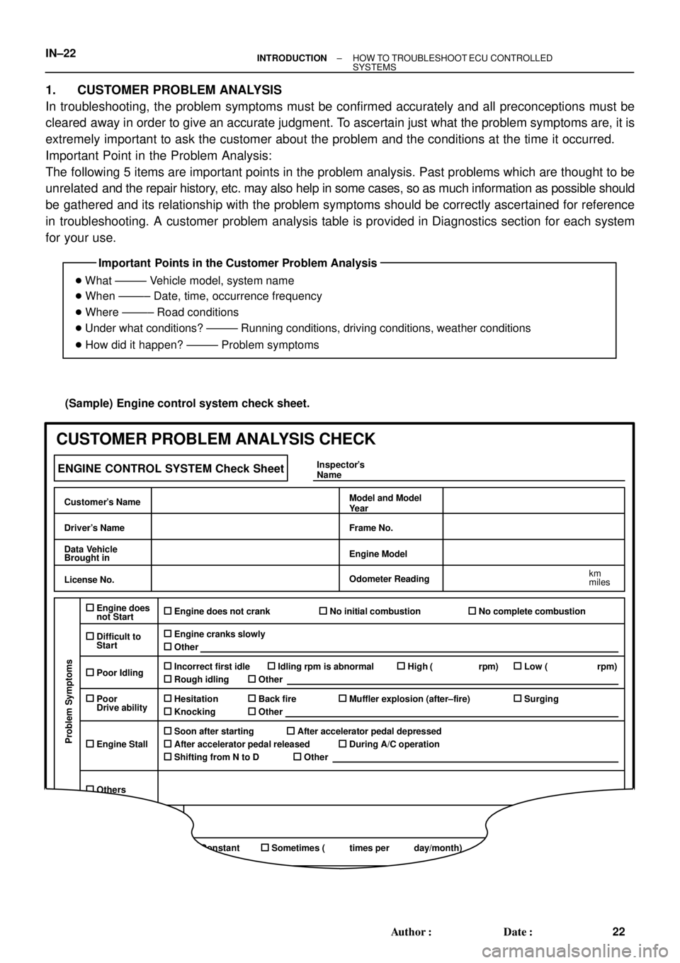
Important Points in the Customer Problem Analysis
� What ±±±±± Vehicle model, system name
� When ±±±±± Date, time, occurrence frequency
� Where ±±±±± Road conditions
� Under what conditions? ±±±±± Running conditions, driving conditions, weather conditions
� How did it happen? ±±±±± Problem symptoms
(Sample) Engine control system check sheet.
ENGINE CONTROL SYSTEM Check Sheet
Customer's Name
Driver's Name
Data Vehicle
Brought in
License No.
Model and Model
Year
Frame No.
Engine Model
Odometer Reading
km
miles
Problem Symptoms
Engine does
not Start
Difficult to
Start
Poor Idling
Poor
Drive ability
Engine Stall
Others
Engine does not crankNo initial combustionNo complete combustion
Engine cranks slowly
Other
Incorrect first idleIdling rpm is abnormalHigh ( rpm)Low ( rpm)
Rough idling
Other
HesitationBack fireMuffler explosion (after±fire)Surging
Knocking
Other
Soon after startingAfter accelerator pedal depressed
After accelerator pedal released
During A/C operation
Shifting from N to D
Other
Data Problem
ConstantSometimes ( times per day/month)
Inspector's
Name
CUSTOMER PROBLEM ANALYSIS CHECK
IN±22± INTRODUCTIONHOW TO TROUBLESHOOT ECU CONTROLLED
SYSTEMS
22 Author�: Date�:
1. CUSTOMER PROBLEM ANALYSIS
In troubleshooting, the problem symptoms must be confirmed accurately and all preconceptions must be
cleared away in order to give an accurate judgment. To ascertain just what the problem symptoms are, it is
extremely important to ask the customer about the problem and the conditions at the time it occurred.
Important Point in the Problem Analysis:
The following 5 items are important points in the problem analysis. Past problems which are thought to be
unrelated and the repair history, etc. may also help in some cases, so as much information as possible should
be gathered and its relationship with the problem symptoms should be correctly ascertained for reference
in troubleshooting. A customer problem analysis table is provided in Diagnostics section for each system
for your use.
Page 2866 of 4592

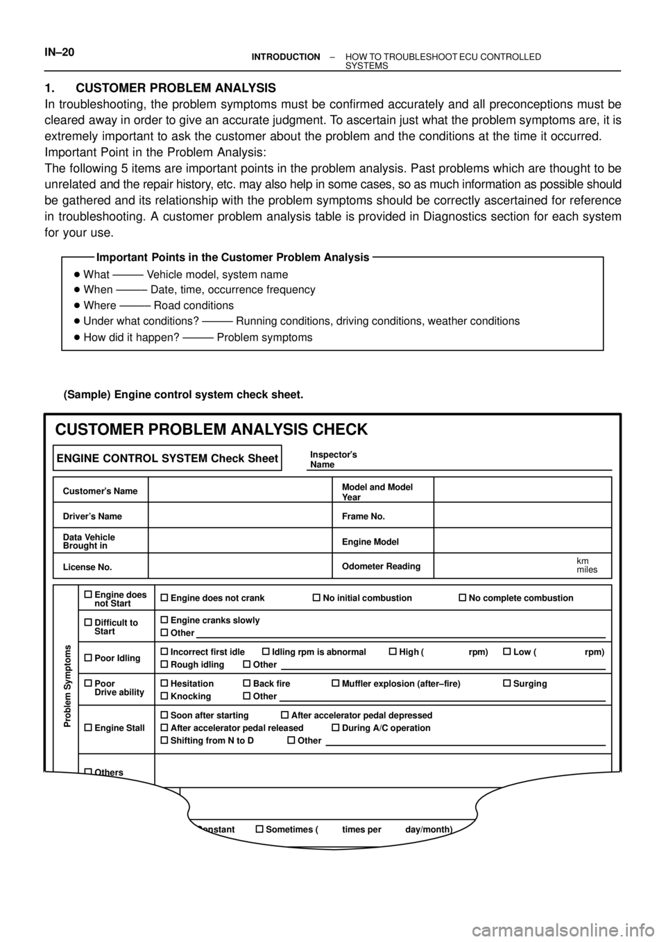
Important Points in the Customer Problem Analysis
� What ±±±±± Vehicle model, system name
� When ±±±±± Date, time, occurrence frequency
� Where ±±±±± Road conditions
� Under what conditions? ±±±±± Running conditions, driving conditions, weather conditions
� How did it happen? ±±±±± Problem symptoms
(Sample) Engine control system check sheet.
ENGINE CONTROL SYSTEM Check Sheet
Customer's Name
Driver's Name
Data Vehicle
Brought in
License No.
Model and Model
Year
Frame No.
Engine Model
Odometer Reading
km
miles
Problem Symptoms
Engine does
not Start
Difficult to
Start
Poor Idling
Poor
Drive ability
Engine Stall
Others
Engine does not crankNo initial combustionNo complete combustion
Engine cranks slowly
Other
Incorrect first idleIdling rpm is abnormalHigh ( rpm)Low ( rpm)
Rough idling
Other
HesitationBack fireMuffler explosion (after±fire)Surging
Knocking
Other
Soon after startingAfter accelerator pedal depressed
After accelerator pedal released
During A/C operation
Shifting from N to D
Other
Data Problem
ConstantSometimes ( times per day/month)
Inspector's
Name
CUSTOMER PROBLEM ANALYSIS CHECK
IN±20± INTRODUCTIONHOW TO TROUBLESHOOT ECU CONTROLLED
SYSTEMS
1. CUSTOMER PROBLEM ANALYSIS
In troubleshooting, the problem symptoms must be confirmed accurately and all preconceptions must be
cleared away in order to give an accurate judgment. To ascertain just what the problem symptoms are, it is
extremely important to ask the customer about the problem and the conditions at the time it occurred.
Important Point in the Problem Analysis:
The following 5 items are important points in the problem analysis. Past problems which are thought to be
unrelated and the repair history, etc. may also help in some cases, so as much information as possible should
be gathered and its relationship with the problem symptoms should be correctly ascertained for reference
in troubleshooting. A customer problem analysis table is provided in Diagnostics section for each system
for your use.
Page 2957 of 4592
MX056±01
MT0791
Synchronizer Ring Spacer
4th Gear
Snap Ring
Rear BearingNeedle Roller Bearing
Snap RingSpring
Shifting KeyNo.2 Clutch HubNo.2 Hub SleeveSynchronizer Ring3rd GearNeedle Roller Bearing
�Input Shaft Front Bearing Inner Race
Input Shaft
�Non±reusable part MX±24
± MANUAL TRANSAXLE (E153)INPUT SHAFT
1825 Author�: Date�:
INPUT SHAFT
COMPONENTS