Page 1688 of 4592

High
Accumulator Control Pressure
D00060
(*) Duty Ratio
The duty ratio is the ratio of the period of continuity in one cycle.
For example, if A is the period of continu")
AT5608
0
1
Electric Current (A)
High
Accumulator Control Pressure
D00060
(*) Duty Ratio
The duty ratio is the ratio of the period of continuity in one cycle.
For example, if A is the period of continuity in one cycle, and B is the period of non±continuity, then
D000621 msec./div.5 V/div.
GND Reference
Waveform between terminals SLN
+
and SLN± when engine is idling.Waveform between terminals SLN
+
and SLN± when during shift change.
1 msec./div.5 V/div.
GND DI±476
± DIAGNOSTICSAUTOMATIC TRANSAXLE (A541E)
711 Author�: Date�:
DTC P1765Linear Solenoid for Accumulator Pressure Control
Circuit Malfunction (Shift Solenoid Valve SLN)
CIRCUIT DESCRIPTION
The shift solenoid valve SLN controls the hydraulic pressure
acting on the accumulator control valve when gears are shifted
and performs smooth gear shifting.
The ECM determines optimum operating pressure according to
the signals from the throttle position sensor, vehicle speed sen-
sor and direct clutch speed sensor and controls the volume of
current flow to the solenoid valve.
The amount of current to the solenoid is controlled by the (*)
duty ratio of ECM output signals, causing a momentary change
to the hydraulic pressure acting on the clutches during gear
shifting.
When the duty ratio is high, the hydraulic pressure acting on the
clutches is low.
DTC No.DTC Detecting ConditionTrouble Area
P1765
After the engine is warmed up, the current flow to the shift
solenoid valve SLN for 1 sec or more under condition (a) or
(b):
(a) Engine speed: 500 rpm or more
(b) Park/neutral position switch: ON (P or N position)
�Open or short in shift solenoid valve SLN circuit
�Shift solenoid valve SLN
�ECM
DI02Q±02
Page 1696 of 4592
D01899
Cruise Control ECU
14
ODY±B7B+
OD1ECM
C15
E10E7
*1: Except California, w/ Engine Immobilizer and / or TRAC
*2: California, w/ Engine Immobilizer and / or TRAC*2
*1
24 DI±484
± DIAGNOSTICSAUTOMATIC TRANSAXLE (A541E)
719 Author�: Date�:
O/D Cancel Signal Circuit
CIRCUIT DESCRIPTION
While driving uphill with cruise control activated, in order to minimize gear shifting and provide smooth cruis-
ing overdrive may be prohibited temporarily under some condition.
The cruise control ECU sends O/D cut signals to the ECM as necessary and the ECM cancels overdrive
shifting until these signals are discontinued.
WIRING DIAGRAM
DI02S±02
Page 1699 of 4592
D01900
ECM
4E7OD2B+
G±O
IG1 C
CC
O2 O/D Main
Switch O/D Indicator
Light
C8 712
R±L
D
Ignition Switch
11K2
1DGAUGE J/C J4
G±OG±O
IG3
J/C J6
G±O
O2
B±Y
AM11B 1K
C10
AM1
F9 D
R±L
I16 W 21
24
I16 2
12
B±R
B±R
B±R1
2
F9Fusible Link Block
FL Main
Battery 1
F4B±GW±B
A
J/C J5
IF A
W±B
Left Kick Panel
*1: Except California, w/ Engine Immobilizer and / or TRAC
*2: California, w/ Engine Immobilizer and / or TRACInstrument Panel J/B
Instrument Panel J/B11106 *2*1
ALTE8
± DIAGNOSTICSAUTOMATIC TRANSAXLE (A541E)
DI±487
722 Author�: Date�:
O/D Main Switch & O/D OFF Indictor Light Circuit
CIRCUIT DESCRIPTION
The O/D main switch contacts go open when the switch is pushed in and go closed when it is pushed out.
In O/D main switch at OFF position, the O/D OFF indicator light lights up, and the ECM prohibits shifting over-
drive.
WIRING DIAGRAM
DI1KD±01
Page 2091 of 4592

DI08L±13
± DIAGNOSTICSCRUISE CONTROL SYSTEM
DI±879
111 4 Author�: Date�:
PROBLEM SYMPTOMS TABLE
SymptomSuspect AreaSuspect AreaSee pageSee
page
SET not occourring or CANCEL occurring.
(DTC is Normal)
3. Main Switch Circuit
(Cruise control switch)
4. Vehicle Speed Sensor
5. Control Switch Circuit
(Cruise control switch)
6. Stop Light Switch Circuit
7. Park/Neutral Position Switch Circuit
8. Clutch Switch
9. Actuator Motor Circuit
10.Cruise Control Cable
11. Cruise Control ECU
DI±912
DI±888
DI±892
DI±898
DI±904
DI±907
DI±881
DI±918
IN±31
SET not occurring or CANCEL occurring.
(DTC dose not output)1. ECU Power Source Circuit
2. Cruise Control ECUDI±909
IN±31
Actual vehicle speed deviates above or below the set speed.
1. Cruise Control Cable
2. Vehicle Speed Signal Abnormal
3. Electronically Controlled Transmission
Communication Circuit
4. Actuator Motor Circuit
5. Idle Signal Circuit
(Main throttle position sensor)
6. Cruise Control ECUDI±918
DI±891
DI±901
DI±881
DI±895
IN±31
Gear shifting frequent between 3rd O/D when driving on uphill
road. (Hurting)1. Electronically Controlled Transmission
Communication Circuit
2. Cruise Control ECU
DI±901
IN±31
Cruise control not cancelled, even when brake pedal is de-
pressed.
1. Cruise Control Cable
2. Stop Light Switch Circuit
3. Actuator Motor Circuit
4. Cruise Control ECUDI±918
DI±898
DI±881
IN±31
Cruise control not cancelled, even when transmission is shifted to
ºNº postion.
1. Cruise Control Cable
2. Park/Neutral Position Switch Circuit
3. Actuator Motor Circuit
4. Cruise Control ECUDI±918
DI±904
DI±881
IN±31
Cruise control not cancelled, even when clutch pedal is de-
pressed.
1. Cruise Control Cable
2. Clutch Switch Circuit
3. Actuator Motor Circuit
4. Cruise Control ECUDI±918
DI±907
DI±881
IN±31
Control switch does not operate.
(SET/COAST, ACC/RES, CANCEL not possible)
1. Cruise Control Cable
2. Control Switch Circuit
3. Actuator Motor Circuit
4. Cruise Control ECUDI±918
DI±892
DI±881
IN±31
SET possible at 40 km/h (25 mph) or less, or CANCEL does not
operate at 40 km/h (25 mph) or less.
1. Cruise Control Cable
2. Vehicle Speed Signal Abnormal
3. Actuator Motor Circuit
4. Cruise Control ECUDI±918
DI±891
DI±881
IN±31
Poor response is in ACCEL and RESUME modes.
1. Cruise Control Cable
2. Electronically Controlled Transmission
Communication Circuit
3. Actuator Motor Circuit
4. Cruise Control ECUDI±918
DI±901
DI±881
IN±31
O/D does not resume, even though the road is not uphill.
1. Electronically Controlled Transmission
Communication Circuit
2. Cruise Control ECU
DI±901
IN±31
Page 2113 of 4592

*3: 5S±FE (w/o Immobiliser)
ECT No.2
SolenoidECT C15
6
C15 Y±B
L±B ECM
24 18 20
E8 E7 E7
*1 *2 *3 OD1
8216
E11
E9 E9
*1 *2 *")
I08432
S2OD 14Cruise Control ECU *1: 1MZ±FE
*2: 5S±FE (w/ Immobiliser)
*3: 5S±FE (w/o Immobiliser)
ECT No.2
SolenoidECT C15
6
C15 Y±B
L±B ECM
24 18 20
E8 E7 E7
*1 *2 *3 OD1
8216
E11
E9 E9
*1 *2 *3L±B L±B7
II2 J26
*1
J25*2
J/C
A
AA
± DIAGNOSTICSCRUISE CONTROL SYSTEM
DI±901
1136 Author�: Date�:
Electronically Controlled Transmission Communication Circuit
CIRCUIT DESCRIPTION
When driving uphill under the cruise control, in order to reduce shifting due to ON±OFF overdrive operation
and to provide smooth driving, when down shifting in the electronically controlled transmission occurs, a sig-
nal to prevent upshift until the end of the uphill slope is sent from the cruise control ECU to the electronically
controlled transmission.
Terminal ECT of the cruise control ECU detects the shift change signal (output to electronically controlled
transmission No. 2 solenoid) from the ECM.
If the vehicle speeds down, also when terminal ECT of the cruise control ECU receives down shifting signal,
it sends a signal from terminal OD to ECM to cut overdrive until the end of the uphill slope, and the gear shifts
are reduced and gear shift points in the electronically controlled transmission are changed.
WIRING DIAGRAM
DI08U±11
Page 2117 of 4592
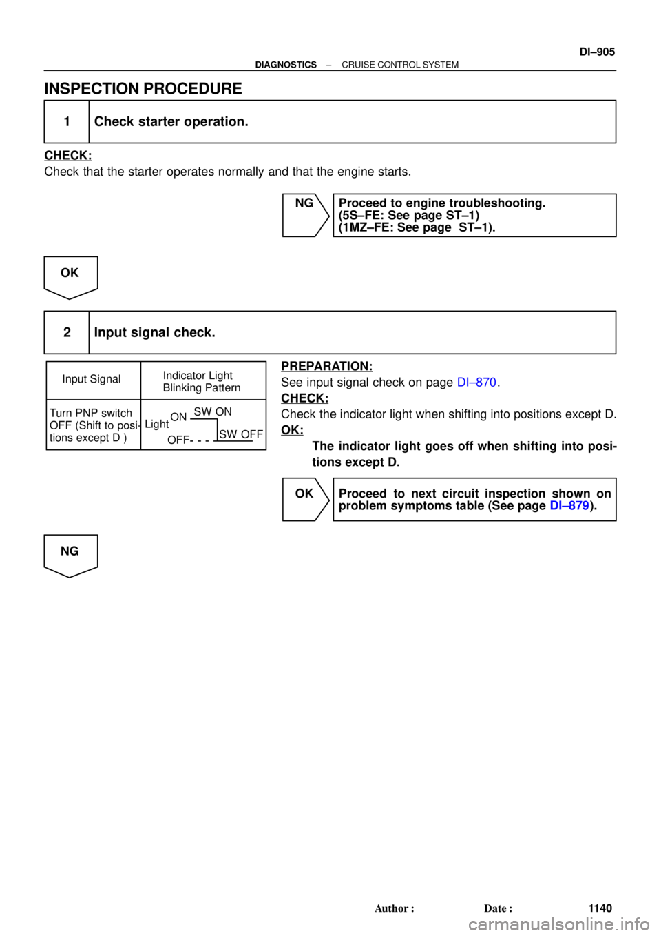
Input SignalIndicator Light
Blinking Pattern
Turn PNP switch
OFF (Shift to posi-
tions except D )LightON
OFFSW ON
SW OFF
± DIAGNOSTICSCRUISE CONTROL SYSTEM
DI±905
1140 Author�: Date�:
INSPECTION PROCEDURE
1 Check starter operation.
CHECK:
Check that the starter operates normally and that the engine starts.
NG Proceed to engine troubleshooting.
(5S±FE: See page ST±1)
(1MZ±FE: See page ST±1).
OK
2 Input signal check.
PREPARATION:
See input signal check on page DI±870.
CHECK:
Check the indicator light when shifting into positions except D.
OK:
The indicator light goes off when shifting into posi-
tions except D.
OK Proceed to next circuit inspection shown on
problem symptoms table (See page DI±879).
NG
Page 2118 of 4592
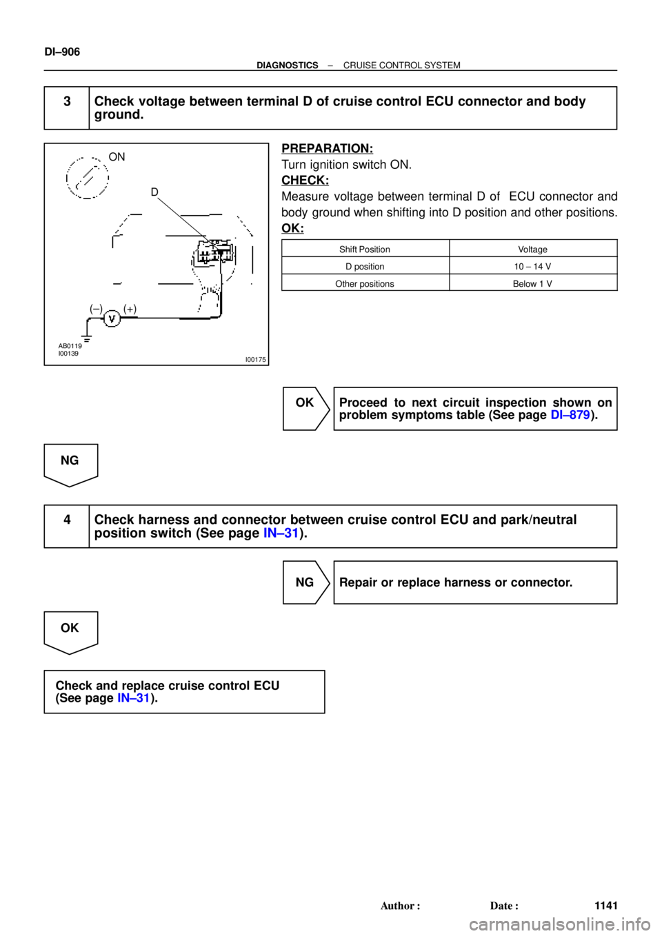
AB0119
I00139
I00175
ON
D
(±) (+)
DI±906
± DIAGNOSTICSCRUISE CONTROL SYSTEM
1141 Author�: Date�:
3 Check voltage between terminal D of cruise control ECU connector and body
ground.
PREPARATION:
Turn ignition switch ON.
CHECK:
Measure voltage between terminal D of ECU connector and
body ground when shifting into D position and other positions.
OK:
Shift PositionVoltage
D position10 ± 14 V
Other positionsBelow 1 V
OK Proceed to next circuit inspection shown on
problem symptoms table (See page DI±879).
NG
4 Check harness and connector between cruise control ECU and park/neutral
position switch (See page IN±31).
NG Repair or replace harness or connector.
OK
Check and replace cruise control ECU
(See page IN±31).
Page 2119 of 4592

LightON
OFFSW ON
SW OFF
± DIAGNOSTICSCRUISE CONTROL SYSTEM
DI±907
1142 Author�: Date�:
Clutch Switch Circuit
C")
Input Signal
Indicator Light
Blinking Pattern
Clutch switch
OFF (Depress
clutch pedal)
LightON
OFFSW ON
SW OFF
± DIAGNOSTICSCRUISE CONTROL SYSTEM
DI±907
1142 Author�: Date�:
Clutch Switch Circuit
CIRCUIT DESCRIPTION
When the clutch pedal is depressed, the clutch switch sends a signal to the cruise control ECU. When the
signal is input to the cruise control ECU during cruise control driving, the cruise control ECU cancels cruise
control.
WIRING DIAGRAM
Refer to PNP switch circuit on page DI±904.
INSPECTION PROCEDURE
1 Check starter operation.
CHECK:
Check that the starter operates normally and that the engine starts.
NG Proceed to engine troubleshooting
(5S±FE: See page ST±1)
(1MZ±FE: See page ST±1).
OK
2 Input signal check.
PREPARATION:
See input signal check on page DI±870.
CHECK:
Check the indicator lights when clutch pedal is depressed.
OK:
The indicator light goes off when shifting into clutch
pedal is depressed.
OK Proceed to next circuit inspection shown on
problem symptoms table (See page DI±879).
NG
DI08W±04