1999 TOYOTA CAMRY radiator sensor
[x] Cancel search: radiator sensorPage 4467 of 4592
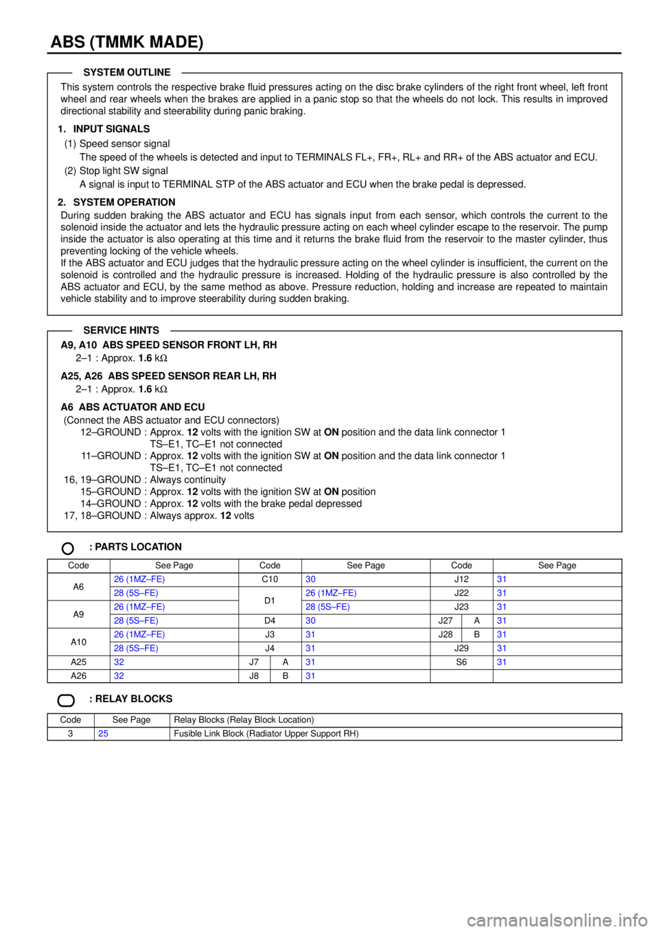
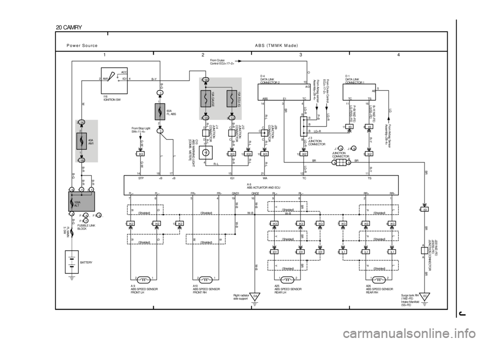
ABS (TMMK MADE)
This system controls the respective brake fluid pressures acting on the disc brake cylinders of the right front wheel, left front
wheel and rear wheels when the brakes are applied in a panic stop so that the wheels do not lock. This results in improved
directional stability and steerability during panic braking.
1. INPUT SIGNALS
(1) Speed sensor signal
The speed of the wheels is detected and input to TERMINALS FL+, FR+, RL+ and RR+ of the ABS actuator and ECU.
(2) Stop light SW signal
A signal is input to TERMINAL STP of the ABS actuator and ECU when the brake pedal is depressed.
2. SYSTEM OPERATION
During sudden braking the ABS actuator and ECU has signals input from each sensor, which controls the current to the
solenoid inside the actuator and lets the hydraulic pressure acting on each wheel cylinder escape to the reservoir. The pump
inside the actuator is also operating at this time and it returns the brake fluid from the reservoir to the master cylinder, thus
preventing locking of the vehicle wheels.
If the ABS actuator and ECU judges that the hydraulic pressure acting on the wheel cylinder is insufficient, the current on the
solenoid is controlled and the hydraulic pressure is increased. Holding of the hydraulic pressure is also controlled by the
ABS actuator and ECU, by the same method as above. Pressure reduction, holding and increase are repeated to maintain
vehicle stability and to improve steerability during sudden braking.
A9, A10 ABS SPEED SENSOR FRONT LH, RH
2±1 : Approx. 1.6 kW
A25, A26 ABS SPEED SENSOR REAR LH, RH
2±1 : Approx. 1.6 kW
A6 ABS ACTUATOR AND ECU
(Connect the ABS actuator and ECU connectors)
12±GROUND : Approx. 12 volts with the ignition SW at ON position and the data link connector 1
TS±E1, TC±E1 not connected
11±GROUND : Approx. 12 volts with the ignition SW at ON position and the data link connector 1
TS±E1, TC±E1 not connected
16, 19±GROUND : Always continuity
15±GROUND : Approx. 12 volts with the ignition SW at ON position
14±GROUND : Approx. 12 volts with the brake pedal depressed
17, 18±GROUND : Always approx. 12 volts
: PARTS LOCATION
CodeSee PageCodeSee PageCodeSee Page
A626 (1MZ±FE)C1030J1231A628 (5S±FE)D126 (1MZ±FE)J2231
A926 (1MZ±FE)D128 (5S±FE)J2331A928 (5S±FE)D430J27A31
A1026 (1MZ±FE)J331J28B31A1028 (5S±FE)J431J2931
A2532J7A31S631
A2632J8B31
: RELAY BLOCKS
CodeSee PageRelay Blocks (Relay Block Location)
325Fusible Link Block (Radiator Upper Support RH)
SYSTEM OUTLINE
SERVICE HINTS
Page 4543 of 4592
J OVERALL ELECTRICAL WIRING DIAGRAM
1
234
2 CAMRY(
Cont. next page)
5A
IGN 2
7ACC
IG1
IG2
ST2 AM1 4
6 AM2
1F 2F1J 10 1K2
2L 42J8
1B 41B1
2A 1
1C
B1K 5
1B 51K 31C8
1W 7
2C 5 2F 42J22C102 1
3 51 1
1 1
4 EB1
5 4
M
BLAB
AA
1J 8
1J 7
IGInstrument panel
br ac e LHC
AB
B
AW± R
2K 7
EBLeft radiator
si de s uppor t1K 1
1D 2
B±G B±R B±R
B±R B±R
B W W± RB±YW± B W± BB±Y B± YR±L R±L G±R
W±B BW±B W±BBR
W B±Y
BR
G±R
G±R
B±Y BR
B±R
B±R B±Y
B± RW
B±R
1A
G±R
L±B
2 7 B± Y
D D
JUNCTI ON CONNE CT OR 45 16
W± B W± B
A
JUNCTION CONNECTOR
FUSIBLE LINK BLOCK L±B G± R
Under the lef t
center pillar BATTERY
FL
1. 25B 100A ALT
7. 5A OBD40A AM1
1 2I16
IGNI TION SW
30A AM215A EFI EFI RELAY CIR OPN RELAY
F14
FUEL
PUMP
J40
JUNCTI ON
CONNE CTORJ11
JUNCTION
CONNECTOR
C10
MALFUNCTI ON INDICATOR LAMP
[COMB. METER] J 4
JUNCTION
CONNECTOR 10A GAUGE
D 5
DA TA L I NK
CONNE CTOR 3
(
Shielded)
BAT
CG S G
BR
J
L
M
NE B
C
235 1
Engine Control and Engine Immobiliser System (
1M Z± FE)
Power Source
BR B±Y
L±W
L±W
B±Y
BR 12 38F
E1 +BTE1
I H B±R
25A A/F HTR
2
11
1
FL MAIN
3. 0WK D
1 ES1CA
ABCA
B
BBRG B±WB±R
B±W
B±R B±W
A/F HTR RELAY(
*1) JUNCTI ON
CONNE CTORB±WW± B
BW± B
B
W± B
L
B(
*1) BR
LW W
7ID1
L±B
C F 4 F 6A, FF 9 , B J35 J36A, B J 7 J 8A,
, J 8 J 7 A B 22
22
W7SIL
C
A
W W
(
Shielded)BR C C
J 3
JUNCTION CONNECTOR
CW From Airbag
Sensor Assembly< 28±4>
* 1 : Califor nia
II3 12
B±RA B±R
D 1
DATA LI NK
CONNECTOR 1
51
32
(
*1) (
*1)
(
*1)
(
*1)(
*1)
(
*1)
(
*1)
(
*1)7IK1 B±R
B±RB± R
Page 4550 of 4592
J
1
234
4 CAMRY
2ACC
IG1
IG2
ST2 AM1 4
6 7AM2
1K 5
1B 5
2L 4
30A
AM2
40A AM1
1K 2
1B 12A115A
EF I
2 1
3 5 2K 72J8
2F 42J2
1C 1F 2F
1A1K 3
5A
IGN
1W 7
BA BB
EBLeft radiator
side suppor tCA CA
AB10A
GA U GE 1K 11J1
1D 2
IFLeft kick panel 12 A 16 B7C 6A 11A 7A 10A 8A 9A43109872
LL 2L DL NL RL PL
4II2 3 II3 1IJ1 9II2 6II2 5II2
15 IG3 14 IG3 13 IG3 16 IG3 1H101V 5 II22
1 2
ECRear side of
surge tank 1DA
D
A C AA
E
A
A C DD
DA EE A
A
6 3 2 1 4 2
A B±W
B±Y B±R W± RB±Y WR±LR± L
R± B R± BY R± L
W± B
G± W
R± B
R
B±R
L±W
YYL±W(
*3)
0 (
*4) B±RR R±B G±W G±W
R± B
R
B±R
O
Y
R± L B±R
L±W(
*3)
0 (
*4)
YW± B
G±O G±O
BR
BR
R
G
L±B
L±B L±B
V
P±L
W±L
B±Y R± B
B±Y B±YL RY WB
B±Y
W± B B±YY
B
B±R B±RB±R
B±G WW± R R± LR±L R± L
B± Y
B±R
W± B
W± B
+B SLN± SLN+ SL S1 S2 NC2± NC2+ E01 E02 BATT NSW VC VTA1 THW E2 L 2 R I16
IGNITION SW
JUNCTION
CONNECTOR
EF I REL AY
100A
ALTJ24
JUNCTION
CONNECTOR
ENGI NE CONTROL MODULE See Engine Control
and Engine Immobiliser
System< 2±9> < 2±10> < 2±11>
J26
JUNCTION
CONNE CTOR
FL MAIN
3. 0W
V 3
VEHI CLE SPEED SENSOR
(
Electronically Controlled
Transmission)
E 3
EL ECT RONI CAL LY CONT ROL LED
TRANSMI SSI ON SOL ENOI D BATTERY
FUSI BLE LINK BLOCKJUNCTION CONNECTOR J29
JUNCTION
CONNECTORJ29
JUNCTION
CONNECTOR
J 6
JUNCTION
CONNECTOR
J 4
JUNCTI ON
CONNE CTORO/D OFFL 2 D N R P
COMBINATION METER
J 5
JUNCTION
CONNECTOR O 2
O/ D MAIN SW
Electronically Controlled Transmission and A/T Indicator (
1M Z±FE)
Power Source
SLN± SLN+ SL S1 S2JUNCTI ON
CONNE CTOR
Fr om
Cruise Contr ol
ECU< 17±3> L±R
IDLO
11 IG3
G± O
C
G±O OD2
Y±BOD1Fro m Cr ui s e
Co nt r ol E CU
< 17±3>CP 1
A/ T INDICATOR LIGHT SW
[PARK/NEUTRAL POSI TION SW]
2C 5
W± B W± BBR
E03L±W(
*3)
0 (
*4) Y
B±R B±R
B±W
CC
J35
JUNCTION
CONNECTOR
C F 4 F 6A, FF 9 , B J27 J28A,
, C 9 C 8A B, C10C J28 B
B J27 J28A,
B±W
, E 8 E 7 A B , E 9 C , E10 DIGSW MREL
7II2 L±B* 3 : TMC Made
* 4 : TMMK M ade
1A B20 12 B 3 B 2 B 4 B24 B A 2 8A
24 16A19E20E9E7E8E 14E 21E31E26 E 10 B30 E 2D 23D 14D 18DF
B
F
B* 2 : Ex cept Calif ornia * 1 : California
V± W
To Speedometer
[Comb. Meter]
< 25±8>
SPD 22 B
E E1 1 ,
ED Sur ge tank RHA A
A J22
JUNCTI ON
CONNE CT OR
BR BRE1
BR
17 D
B
B A
BR
BRJ26
JUNCTI ON
CONNE CT OR (
*1)
(
*1)
(
*2)
Page 4553 of 4592
J OVERALL ELECTRICAL WIRING DIAGRAM
1
234
7 CAMRY
40A
AM11K 2
1B 12ACC
IG1 AM1 4
7. 5A
DOME 1K 12A 1
1J 12J 12
1V 71W 1
FB
1F 2F 1C
1ADA40A
MAIN 2B 3
3 4
2 1
2K 82G3
IG1613
EL H T HF HI
OFF
LIGHT
CONTROL SW
TAIL
HEAD
LOW
HIGH
FLASH
DI MM ER SW
8
C1 3
COMBINATION SW
21
12
B
B
B±YB
B
W
R±L RR
R± L
B±R B±R
B±R4R± B
BB3
8
1J 7
1J
IFLeft kick panel 3IG1
10A
H±LP RH(
LWR)
10A
H±LP LH(
LWR)
15A
HEAD RH(
UPR)
15A
HEAD LH(
UPR)
2G 52G222 2G 42
21
321
3
4 3
2 1 3 1
24
5A DRL NO. 2
2222
22
2 2 2 2
1
2
7 EB1
EBLeft radiator
side s uppor t A
AA81
A9
A FUSIBLE LINK
BLOCK
R± W R± WY R
R
To Brak e Fluid
Level Warning
SW< 25±5>To Parking
Br ak e SW
< 25±5> From Generator
< 1±4>
R±B
W± B R±Y R±WR±Y
R± L
B±G SHORT PIN HEAD RELAY
IG +BBRK PKB CHG± H±LP
EHHI IND DIM I16
IGNITION SW
J 1
JUNCTION CONNECTOR
W± B
J 7
JUNCTI ON
CONNE CT ORJ 5
JUNCTI ON
CONNE CTOR
J11
JUNCTION
CONNECTOR
To Theft Deterr ent ECU
< 15±3> I17
I NT EGRA TI ON RE LA Y
BATTERY FL MAIN
3. 0W
W± BR±Y
7W± RR
W± BR±BR
R±W
R±B
W±B W±B W± B
R
2
DI M RE L AY
C 9
HIGH BEAM INDI CATOR
LIGHT[COMB. METER]
DRL NO. 4
RELAYD 2
DAYTIME RUNNING
LI GHT RESI ST OR H 1
HEADLIGHT
LHH 2
HEADLI GHT
RHR±B
R R±G
R±L
R±B
Power SourceHeadlight (
w/ Daytime Running Light)
R±B
R± L
100A
AL T
W± B R±Y R±Y
10A GAUGE
2 1
8 EB1
Ins trument panel
br ace LH R±BB
W± R
32 11
A , F 6 F 4 A C , F 9 FTAIL T
G±R Fr om
TAILLIGHT Relay
< 10±1> < 11±2>G± Y To Integration
Relay
< 10±1> < 11±1>
JUNCTION
CONNECTORB A J27 J28,
8IG1 9IG1 4IG1
CS E CSO CSB3 4 1
GR±R
P±L
V±Y V±YP±L GR±R
A40
AUTOMATIC LIGHT
CONTROL SENSOR
D 6
DA YT I ME RUNNI NG L I GHT RE L AY(
Mai n)
B
R±B
R±B
R
RH±ON CLTB CLTS CLTE
6155 23 4141322161719
20 18 21 3 2 12
Page 4568 of 4592
J
1
234
20 CAMRY
2ACC
IG1 AM1 4
1K 2
40A
AM1
1B 1
1F 2F 1B
1A3
60A
FL ABS
3
1IK31K 1
1J 9 1D 2
10A GAUGE 15A ECU±IG
5IK3 12IG3 10IK3 12IK211 II3 8 II3
5IK2
21 1IK2 6IK2 13IK2
21
EA12 3 I K3 9 IK3 8 IK3 7 IK3 2 IK3
126IK3
3ID1 9ID1 4ID1 3 IL1 2IL1 1 IL116 11
B C C D
4 2
1
76 54191698 214 14
B
C
C 1
2
14 18 17 15 21 12 11C D
B
LG±R B±Y
R±L
W± B
W± B (
Sh ie l de d)
(
Sh ie l de d)
(
Sh ie l de d)(
Shielded) (
Shielded) (
Shielded)
(
Shielded) (
Shielded) (
Shielded)
(
Shielded)TS TC TC ABS
RR± RR+ RL ± RL+ GND2 GND1 FR± FR+ FL ± FL +STP +B +B IG1 WA TC TS
L
P L
P L
P
BR
YBR
YBR
Y
G
RG
R WB W±B
W±BW±B
B±G B±R
B±R B±R W
B±G B±G LL
G± W G±W B±R
R±L R±LB±R B±RR±L R±L R±L LG±R LG±R
R±LR± Y R±Y B±Y(
1MZ±FE)
LG(
5S±FE)
P±B(
1MZ±FE)
LG±R(
5S±FE)
LG±R
R± L
Power Source
7
J 4
JUNCTION
CONNECTOR J12
JUNCTION
CONNECTOR J29
JUNCTION
CONNECTOR
I16
IGNITION SW
From Stop Light
SW< 11±4>
C1 0
ABS WARNING LIGHT
[COMB. METER]
J 3
JUNCTION
CONNECTOR D 4
DATA LINK
CONNECTOR 2D 1
DA TA L I NK
CONNE CTOR 1
A 6
ABS ACTUATOR AND ECU
A 9
ABS SPEED SENSOR
FRONT LHA10
ABS SPEED SENSOR
FRONT RHA2 5
ABS SPEED SENSOR
REAR LHA2 6
ABS SPEED SENSOR
REAR RH BATTERY
FL MAIN
3. 0W
100A
AL T
FUSIBLE LINK
BLOCKB
B
P±B LG±R
From Airbag sensor
Assembly< 28±4> Fr om Cruise Contr ol
ECU< 17±2>
Fro m Cr ui s e
Control ECU< 17±2>
10
A/ D
From Airbag Sens or
Assembly< 28±4>
O
5
AB
LG
W±B
EC Surge tank RH
(
1MZ±FE)
Intake Manifold
(
5S±FE)A
J22(
1MZ±FE)
J23(
5S±FE)
JUNCTION CONNECTOR
A 6II3BR BR
Right radiator
side suppor tC
AB
B 3E1
BR
BR JUNCTION
CONNECTOR
BR
BR
ABS (
TMMK Made)
, F 5 F 4 A B ,
F 9 F, J 8 J 7 A B
Page 4591 of 4592

L PART NUMBER OF CONNECTORS
Code Part Name Part NumberCodePart Name Part Number
Note : Not all of the above part numbers of the connector are established for the supply. In case of ordering
a connector or terminal with wire, please confirm in advance if there is supply for it using ªParts Catalog
Newsº (published by Parts Engineering Administration Dept.).
J15Junction Connector90980±10803
J16Junction Connector90980±11661J17Junction Connector90980±11661
J18Junction Connector90980±11542J19Junction Connector90980±11542
J20Junction Connector90980±11539
J21Junction Connector90980±11542
J22Junction Connector90980±11539J23Junction Connector90980±11539
J24Junction Connector
J25Junction Connector90980±11529
J26Junction Connector
J27Junction Connector90980±11661J28Junction Connector90980±11661
J29Junction Connector90980±11502
J30Junction Connector90980±11661J31Junction Connector90980±11661
J32Junction Connector90980±10803
J33Junction Connector
J34Junction Connector90980±11661J35Junction Connector90980±11661
J36Junction Connector
J37Junction Connector90980±11542
J38Junction Connector90980±10803J39Junction Connector90980±10803
J40Junction Connector90980±10976
K 1Knock Sensor 190980±11166K 2Knock Sensor 290980±11166
K 3Key Interlock Solenoid90980±10825
L 1License Plate Light LH90980±11148L 2License Plate Light RH90980±11148
L 3Light Failure Sensor90980±10803
L 4Luggage Compartment Key Unlock SW90980±11212
L 5Luggage Compartment Light90980±11148
L 6Luggage Compartment Light SW90980±11097
M 1Manifold Absolute Pressure Sensor90980±10845
M 2Mass Air Flow Meter90980±11317
M 3Moon Roof Control SW and Relay90980±10799
M 4Moon Roof Motor and Limit SW90980±11011
N 1Noise Filter (Ignition)90980±10843
N 2Noise Filter (Rear Window Defogger)90980±11259
O 1Oil Pressure SW90980±11363
O 2O/D Main SW and A/T Shift Lever
Illumination90980±10795
P 1Park/Neutral Position SW,A/T Indicator Light
SW and Back±Up Light SW90980±11332
P 2Power Steering Oil Pressure SW90980±11428
P 3Parking Brake SW90980±10871
P 4Power Outlet90980±10760
P 5Personal Light90980±10825
P 6Power Window Control SW Front RH90980±10789
P 7Power Window Control SW Rear LH90980±10631P 8Power Window Control SW Rear RH90980±10631
P 9Power Window Master SW and Door Lock
Control SW LH90980±10807
P10Power Window Motor Front LH
P11Power Window Motor Front RH90980±10860P12Power Window Motor Rear LH90980±10860
P13Power Window Motor Rear RH
P14Power Seat Control SW (Driver's Seat)
P15Power Seat Control SW
(Front Passenger's Seat)90980±10803
P16Power Seat Motor
(Driver's Seat Rear Vertical Control)
P17Power Seat Motor
(Driver's Seat Reclining Control)90980±10825
P18Power Seat Motor
(Driver's Seat Slide Control)
P19Power Seat Motors (Driver's Seat)90980±11001
P20Power Seat Motor (Front Passenger's Seat
Rear Vertical Control)
P21Power Seat Motor (Front Passenger's Seat
Reclining Control)90980±10825
P22Power Seat Motor (Front Passenger's Seat
Slide Control)
P23Power Seat Motors
(Front Passenger's Seat)90980±11001
P24Pretensioner LH90980±11862P25Pretensioner RH90980±11862
R 1Radiator Fan Motor90980±10928
R 2Radio and Player90980±10996
R 3Radio and Player90980±10997
R 4Radio and Player90980±11264
R 5Rear Window Defogger SW90980±11280
R 6Remote Control Mirror SW90980±11450
R 7Rheostat90980±10908
R 8Rear Combination Light LH90980±10795
R 9Rear Combination Light LH90980±11001
R10Rear Combination Light RH90980±10795
R11Rear Combination Light RH90980±11001