1999 TOYOTA CAMRY radiator sensor
[x] Cancel search: radiator sensorPage 4190 of 4592
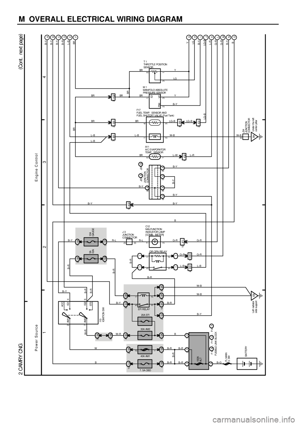
M OVERALL ELECTRICAL WIRING DIAGRAM
1
234
(
Cont . next page)
2 CAMRY CNG
EFI RELAYCIR OPN RELAY
20A EFI
40A AM1 30A AM2
7. 5A OBD
2 1
3 5
2 1
3 5 1J 10 1K22L 41K 5
82J 2K7
11
1B 41B12A12C10 2J 22F4
11 1B 5
L±B
AM2 6
I10
IGNITION SW4 AM1
ST2IG2
2 IG1 ACC
7 2
11K 31K
5A
IGN
4EB1 5EB1
EB Left radiator
s ide s upport 1F 2F 1C
1A
B±G
BATTERY10A
GA UGE
71WB± Y B± Y
1D 2B± Y
FUSIBLE LINK BLOCK10 IF1
FL MAIN
3. 0WBA
100A
AL T
B±Y
1B±R
BB W±R
2
B±R
BR
IG3 9
BR
A
B±R
B±RB
Y
C
LG
Y
B±Y
LG±B
L±W
B±Y
B±Y B±Y
R± L G± R G± R
2
G± R
3
BB±Y W± B M 1
MANIFOLD ABSOLUTE
PRESSURE SENSORT 1
THROTTLE POSITI ON
SENSOR
B±RL±B L±B
L±B G±R
W± R
W
B
IG2 1
B± R F17
FUEL TEMP. SENSOR AND
FUEL SHUTOFF VALVE (
Fuel Tank)
B± R
1
A1 1
A/ C EVAPORATOR
TEMP. SENSOR
ON ML KJI H G
B±R
Y
LG
B± Y
LG±B
L±R
G±R
G±R
B± Y
B
C12
MALFUNCTION
I NDI CA TOR L AMP
[COMB. METER]
7
2 D D
J 3
JUNCTION
CONNECTOR
JUNCTION
CONNECTOR
B±Y
23 31 1
12
R± LB
PIM VCE2
B± R
Power SourceEngine Control
D
E
F
BR
4IB1 BR
3IG2
BR BR
7IB1
LG±B
EA
W±B
L±R
EA BAL±B
B±YB± Y
, F11 F 9 A C , F14 FB J23 J24A,
2C 5
W± B
B±Y L±B
2IG1
BKUnder the left
center pillar B±RB±R
B±Y
B±R
A
J34
JUNCTION
CONNECTOR
W± B
LG±BBR
B± R BR
2IB1
BR4BR
Page 4218 of 4592
1
234
4
B
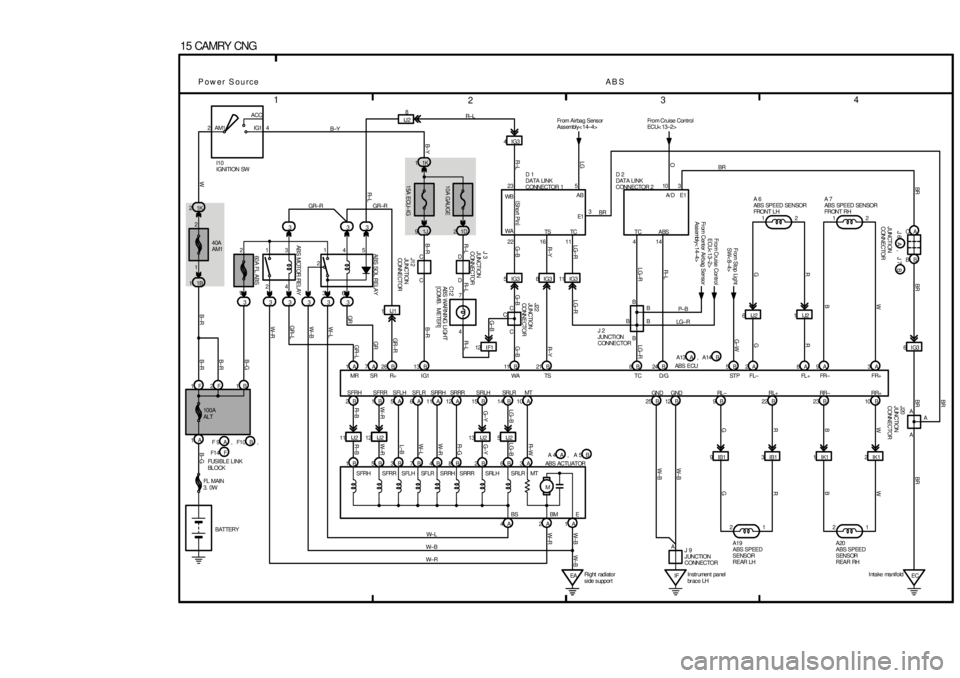
15 CAMRY CNG
W
J12
JUNCTION
CONNE CT ORW
SRRR
B
R
2ACC
IG1 AM1
SFLR 4
SRRH SRLH
G
G±B
SRLR 40A
AM1
W± B
W± R
MTR± W J22
JUNCTION
CONNE CTOR
LG±B
W± L W±RR±GG± Y
1
23
4
L±B
W±R
R±B R± L
31
64
2
B W
3
R
3 1
GR
35
G
3
SFRH
G±W
LG±R
3
ABS SOL RELAYR± L
2
3
LG±R LG±R
SFRR 3
SRRR 3
B± Y
3ABS MOTOR RELAY LG±R
1K 2
R±Y
1B 1
G±BR±Y
1A
G±B
7A
G±B
R± L
26 B
R± L R±L
13 B
B±R
GR ± R B±R
GR
GR±L1K 1
GR
1J 9
W± L
W± B
1D 2
5
GR±L
1F
W±R
2FW
1B
B±G B± G
B±R
B±R B±R
B±Y
11 B GR±R
21 B
W± B
W± R12 I F1
SRRH
W± L12 12
C
6IJ2 D
7
1IJ2 C
2A C
B
8A B
9A
GN D GND3A B 24 5 B 8B IJ28
TC
W± B
1A
W± B
25 B 2B12 B
EA 1B A 6A 11A
2 12 A
1 15 B 14 B A10
1B
21 5B 3B 7B 4B 8BIK1 2
2B 6BABS
IK1 1
3AIB1 3 IB1 99B IG3 4
B 22 C
B 23
M D
1AB 10
4A C
2A
B
SFLH
R
G
J 3
JUNCTION
CONNECTOR
C1 2
ABS WARNI NG LI GHT
[COMB. METER]
I10
IGNITION SW
100A
AL T
,
B
BATTERY FUSIBLE LINK
BL OCKABS ACTUAT OR
FL MAIN
3. 0W
15A ECU±IG10A GAUGE
A 7
ABS SPEED SENSOR
FRONT RH
,
ABS ECUA 6
ABS SPEED SENSOR
FRONT L H
From Stop Light
SW< 8±4>A19
ABS SPEED
SENSOR
REAR LHA20
ABS SPEED
SENSOR
REAR RH
Power SourceAB S1 2
IG3 R±L
MR SR R+ I G1 WA TS TC D/G STP FL± FL+ FR± FR+
RR+ RR± RL+ RL ±
MT SRLHTS
SF LR14
SFLH SFRR4
SFRH
BS BM11
E TC D 1
DATA LINK
CONNECTOR 1
IG3 8 WB
11 16 WA
22
(
Short Pin)23R±L
D 2
DATA LINK
CONNECTOR 2
W± B
Fr om Airbag Sens or
Assembly< 14±4>
J 2
JUNCTI ON
CONNECTORB
B 510
A/ D AB
From Cruise Control
ECU< 13±2>
Fr om Cent er Airbag Sensor
Assembly< 14±4>
P± B
LG±R From Cruise Control
ECU< 13±2>
IFInstr ument panel
br ac e LH AE1
LGO
5IG3A C
EC BB
6IG3
BR BR BRA A BRBR
3
Intake manifold , F10 F 9 A B
A 5 A F1 4 F
A 4 , A14 A13 A B GR±R
1IJ1
IJ2 5 13 IJ2 11 IJ2 12 IJ2
LG±B
G±Y
W± R
R± B
J 9
JUNCTION
CONNECTOR
60A FL ABS
SRLR
Right radiator
s ide s uppor t
JUNCTION
CONNECTORB A J 6 J 7, J20
JUNCTION
CONNECTOR
E13
A
BR
BR
Page 4254 of 4592
![TOYOTA CAMRY 1999 Service Repair Manual G
Position of Parts in Engine Compartment
[1MZ±FE]
I 1 Idle Air Control Valve
I 2 Igniter
I 5 Ignition Coil No.1
I 6 Ignition Coil No.2
I 7 Ignition Coil No.3
I 8 Injector No.1
I 9 Injector No.2
I 10 TOYOTA CAMRY 1999 Service Repair Manual G
Position of Parts in Engine Compartment
[1MZ±FE]
I 1 Idle Air Control Valve
I 2 Igniter
I 5 Ignition Coil No.1
I 6 Ignition Coil No.2
I 7 Ignition Coil No.3
I 8 Injector No.1
I 9 Injector No.2
I 10](/manual-img/14/57448/w960_57448-4253.png)
G
Position of Parts in Engine Compartment
[1MZ±FE]
I 1 Idle Air Control Valve
I 2 Igniter
I 5 Ignition Coil No.1
I 6 Ignition Coil No.2
I 7 Ignition Coil No.3
I 8 Injector No.1
I 9 Injector No.2
I 10 Injector No.3
I 11 Injector No.4
I 12 Injector No.5
I 13 Injector No.6
K 1 Knock Sensor 1
K 2 Knock Sensor 2
M 2 Mass Air Flow Meter
N 1 Noise Filter (Ignition)
O 1 Oil Pressure SW
P 1 Park/Neutral Position SW,A/T Indicator Light SW and
Back±Up Light SW
P 2 Power Steering Oil Pressure SWR 1 Radiator Fan Motor
S 1 Starter
S 2 Starter
T 1 Theft Deterrent Horn
T 2 Throttle Position Sensor
V 2 Vehicle Speed Sensor (Combination Meter)
V 3 Vehicle Speed Sensor
(Electronically Controlled Transmission)
V 4 VSV (EGR)
V 5 VSV (EVAP)
V 6 VSV (Intake Air Control)
W 1 Washer Level Warning SW
W 2 Washer Motor
W 3 Water Temp. Sender
W 4 Water Temp. SW No.1
W 5 Water Temp. SW No.2
Page 4256 of 4592
![TOYOTA CAMRY 1999 Service Repair Manual G
Position of Parts in Engine Compartment
[5S±FE]
I 1 Idle Air Control Valve
I 3 Ignition Coil and Igniter No.1
I 4 Ignition Coil and Igniter No.2
I 8 Injector No.1
I 9 Injector No.2
I 10 Injector No TOYOTA CAMRY 1999 Service Repair Manual G
Position of Parts in Engine Compartment
[5S±FE]
I 1 Idle Air Control Valve
I 3 Ignition Coil and Igniter No.1
I 4 Ignition Coil and Igniter No.2
I 8 Injector No.1
I 9 Injector No.2
I 10 Injector No](/manual-img/14/57448/w960_57448-4255.png)
G
Position of Parts in Engine Compartment
[5S±FE]
I 1 Idle Air Control Valve
I 3 Ignition Coil and Igniter No.1
I 4 Ignition Coil and Igniter No.2
I 8 Injector No.1
I 9 Injector No.2
I 10 Injector No.3
I 11 Injector No.4
I 14 Intake Air Temp. Sensor
K 1 Knock Sensor 1
M 1 Manifold Absolute Pressure Sensor
N 1 Noise Filter (Ignition)
O 1 Oil Pressure SW
P 1 Park/Neutral Position SW,A/T Indicator Light SW and
Back±Up Light SW
P 2 Power Steering Oil Pressure SWR 1 Radiator Fan Motor
S 1 Starter
S 2 Starter
T 1 Theft Deterrent Horn
T 2 Throttle Position Sensor
V 2 Vehicle Speed Sensor (Combination Meter)
V 4 VSV (EGR)
V 5 VSV (EVAP)
W 1 Washer Level Warning SW
W 2 Washer Motor
W 3 Water Temp. Sender
W 4 Water Temp. SW No.1
Page 4264 of 4592

G
Connector Joining Wire Harness and Wire Harness
12211234
56781 2 3 4
5 6 7 8
1234
56XX1 2 3 4
5 6 X X1112
3421
43
1
1
EA1DARK GRAYEB1GRAY
EB1GRAYEB2GRAYEC1DARK GRAY
ES1BLACK(w/ Daytime Running Light)
(w/o Daytime Running Light)
CodeJoining Wire Harness and Wire Harness (Connector Location)
EA1Engine Room Main Wire and Engine Room Main No.3 Wire (Radiator LH)
EB1Cowl Wire and Engine Room Main Wire (Under the Engine Room J/B No 2)EB2Cowl Wire and Engine Room Main Wire (Under the Engine Room J/B No.2)
EC1Engine Wire and Sensor Wire (Head Cover RH)
ES1Engine Wire and Engine Room Main Wire (Under the Engine Room J/B No.2)
Page 4302 of 4592
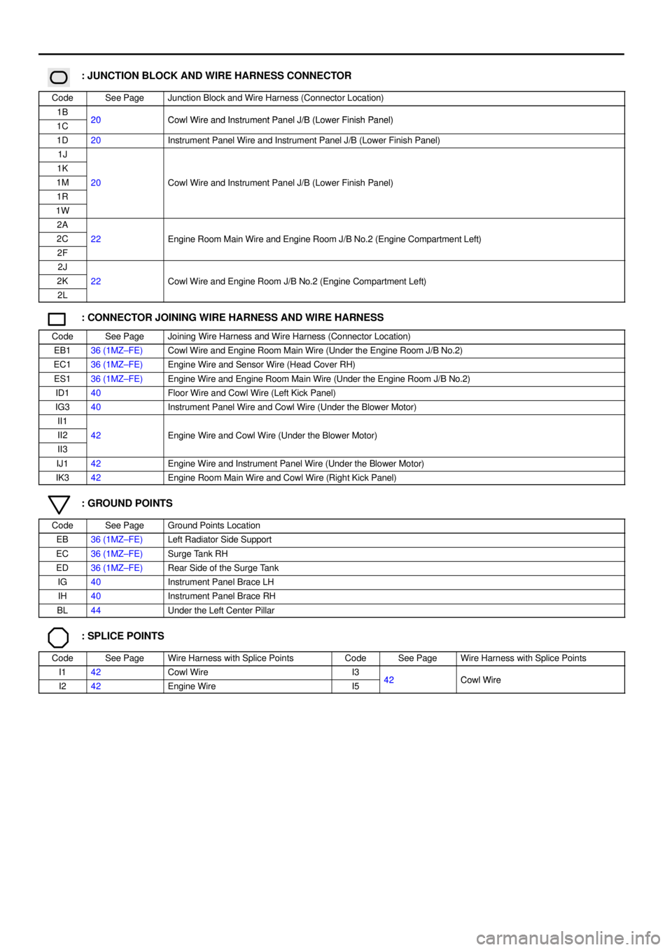
: JUNCTION BLOCK AND WIRE HARNESS CONNECTOR
CodeSee PageJunction Block and Wire Harness (Connector Location)
1B20Cowl Wire and Instrument Panel J/B (Lower Finish Panel)1C20Cowl Wire and Instrument Panel J/B (Lower Finish Panel)
1D20Instrument Panel Wire and Instrument Panel J/B (Lower Finish Panel)
1J
1K
1M20Cowl Wire and Instrument Panel J/B (Lower Finish Panel)
1R
()
1W
2A
2C22Engine Room Main Wire and Engine Room J/B No.2 (Engine Compartment Left)
2F
gg(g)
2J
2K22Cowl Wire and Engine Room J/B No.2 (Engine Compartment Left)
2L
g(g )
: CONNECTOR JOINING WIRE HARNESS AND WIRE HARNESS
CodeSee PageJoining Wire Harness and Wire Harness (Connector Location)
EB136 (1MZ±FE)Cowl Wire and Engine Room Main Wire (Under the Engine Room J/B No.2)
EC136 (1MZ±FE)Engine Wire and Sensor Wire (Head Cover RH)
ES136 (1MZ±FE)Engine Wire and Engine Room Main Wire (Under the Engine Room J/B No.2)
ID140Floor Wire and Cowl Wire (Left Kick Panel)
IG340Instrument Panel Wire and Cowl Wire (Under the Blower Motor)
II1
II242Engine Wire and Cowl Wire (Under the Blower Motor)
II3
g()
IJ142Engine Wire and Instrument Panel Wire (Under the Blower Motor)
IK342Engine Room Main Wire and Cowl Wire (Right Kick Panel)
: GROUND POINTS
CodeSee PageGround Points Location
EB36 (1MZ±FE)Left Radiator Side Support
EC36 (1MZ±FE)Surge Tank RH
ED36 (1MZ±FE)Rear Side of the Surge Tank
IG40Instrument Panel Brace LH
IH40Instrument Panel Brace RH
BL44Under the Left Center Pillar
: SPLICE POINTS
CodeSee PageWire Harness with Splice PointsCodeSee PageWire Harness with Splice Points
I142Cowl WireI342Cowl WireI242Engine WireI542Cowl Wire
Page 4359 of 4592
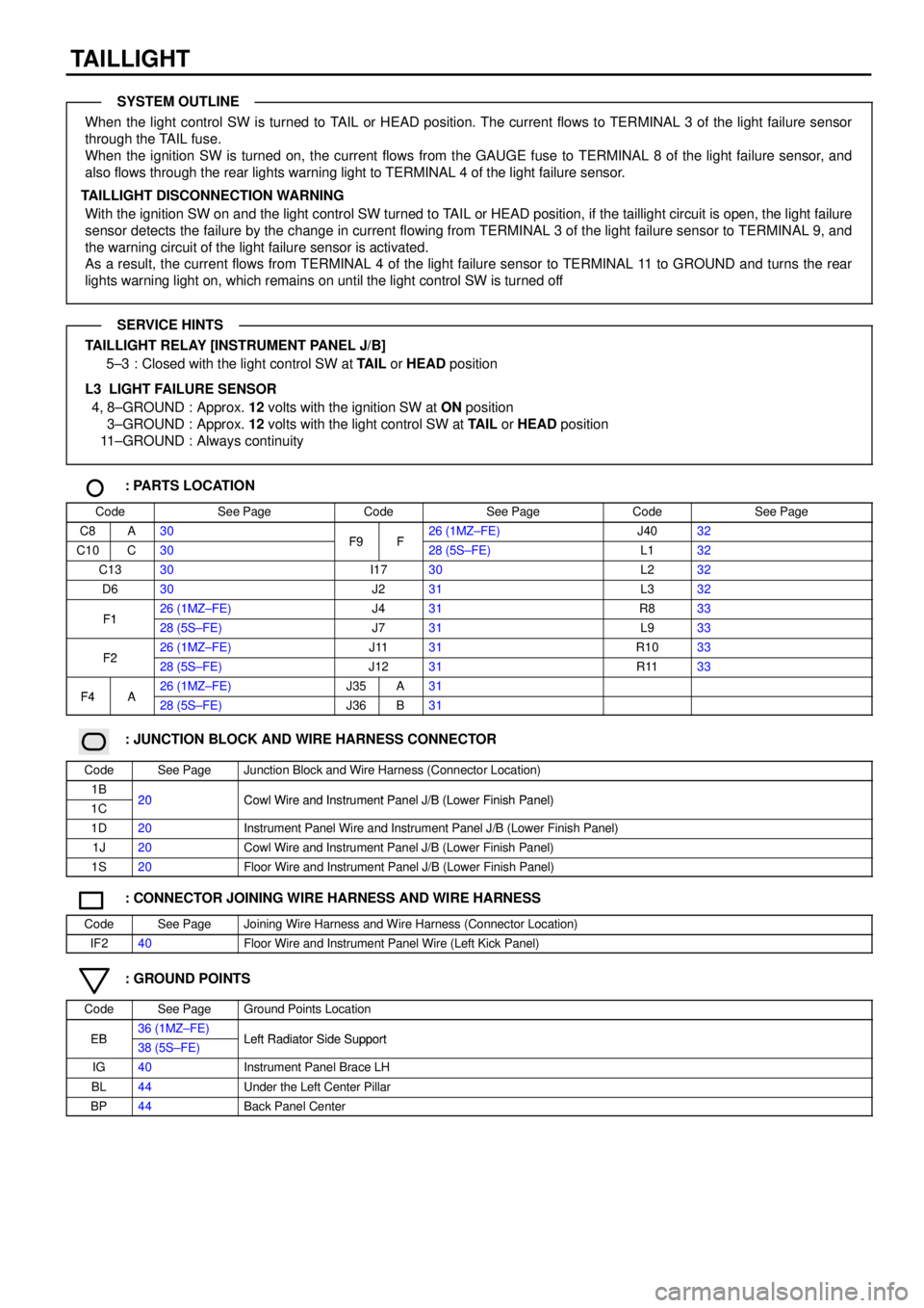
TAILLIGHT
When the light control SW is turned to TAIL or HEAD position. The current flows to TERMINAL 3 of the light failure sensor
through the TAIL fuse.
When the ignition SW is turned on, the current flows from the GAUGE fuse to TERMINAL 8 of the light failure sensor, and
also flows through the rear lights warning light to TERMINAL 4 of the light failure sensor.
TAILLIGHT DISCONNECTION WARNING
With the ignition SW on and the light control SW turned to TAIL or HEAD position, if the taillight circuit is open, the light failure
sensor detects the failure by the change in current flowing from TERMINAL 3 of the light failure sensor to TERMINAL 9, and
the warning circuit of the light failure sensor is activated.
As a result, the current flows from TERMINAL 4 of the light failure sensor to TERMINAL 11 to GROUND and turns the rear
lights warning light on, which remains on until the light control SW is turned off
TAILLIGHT RELAY [INSTRUMENT PANEL J/B]
5±3 : Closed with the light control SW at TAIL or HEAD position
L3 LIGHT FAILURE SENSOR
4, 8±GROUND : Approx. 12 volts with the ignition SW at ON position
3±GROUND : Approx. 12 volts with the light control SW at TAIL or HEAD position
11±GROUND : Always continuity
: PARTS LOCATION
CodeSee PageCodeSee PageCodeSee Page
C8A30F9F26 (1MZ±FE)J4032
C10C30F9F28 (5S±FE)L132
C1330I1730L232
D630J231L332
F126 (1MZ±FE)J431R833F128 (5S±FE)J731L933
F226 (1MZ±FE)J1131R1033F228 (5S±FE)J1231R1133
F4A26 (1MZ±FE)J35A31F4A28 (5S±FE)J36B31
: JUNCTION BLOCK AND WIRE HARNESS CONNECTOR
CodeSee PageJunction Block and Wire Harness (Connector Location)
1B20Cowl Wire and Instrument Panel J/B (Lower Finish Panel)1C20Cowl Wire and Instrument Panel J/B (Lower Finish Panel)
1D20Instrument Panel Wire and Instrument Panel J/B (Lower Finish Panel)
1J20Cowl Wire and Instrument Panel J/B (Lower Finish Panel)
1S20Floor Wire and Instrument Panel J/B (Lower Finish Panel)
: CONNECTOR JOINING WIRE HARNESS AND WIRE HARNESS
CodeSee PageJoining Wire Harness and Wire Harness (Connector Location)
IF240Floor Wire and Instrument Panel Wire (Left Kick Panel)
: GROUND POINTS
CodeSee PageGround Points Location
EB36 (1MZ±FE)Left Radiator Side SupportEB38 (5S±FE)Left Radiator Side Support
IG40Instrument Panel Brace LH
BL44Under the Left Center Pillar
BP44Back Panel Center
SYSTEM OUTLINE
SERVICE HINTS
Page 4461 of 4592
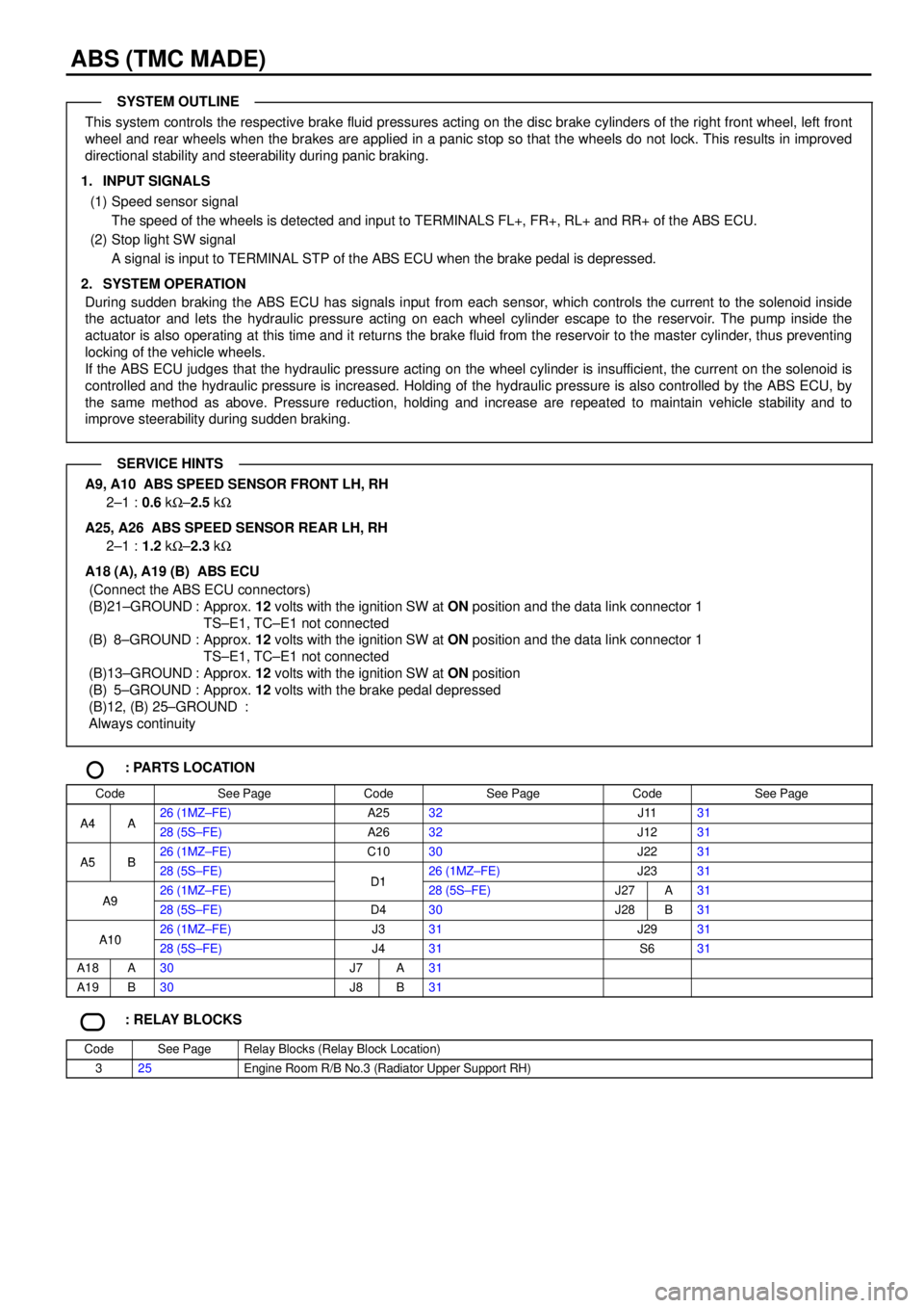
ABS (TMC MADE)
This system controls the respective brake fluid pressures acting on the disc brake cylinders of the right front wheel, left front
wheel and rear wheels when the brakes are applied in a panic stop so that the wheels do not lock. This results in improved
directional stability and steerability during panic braking.
1. INPUT SIGNALS
(1) Speed sensor signal
The speed of the wheels is detected and input to TERMINALS FL+, FR+, RL+ and RR+ of the ABS ECU.
(2) Stop light SW signal
A signal is input to TERMINAL STP of the ABS ECU when the brake pedal is depressed.
2. SYSTEM OPERATION
During sudden braking the ABS ECU has signals input from each sensor, which controls the current to the solenoid inside
the actuator and lets the hydraulic pressure acting on each wheel cylinder escape to the reservoir. The pump inside the
actuator is also operating at this time and it returns the brake fluid from the reservoir to the master cylinder, thus preventing
locking of the vehicle wheels.
If the ABS ECU judges that the hydraulic pressure acting on the wheel cylinder is insufficient, the current on the solenoid is
controlled and the hydraulic pressure is increased. Holding of the hydraulic pressure is also controlled by the ABS ECU, by
the same method as above. Pressure reduction, holding and increase are repeated to maintain vehicle stability and to
improve steerability during sudden braking.
A9, A10 ABS SPEED SENSOR FRONT LH, RH
2±1 :0.6 kW±2.5 kW
A25, A26 ABS SPEED SENSOR REAR LH, RH
2±1 :1.2 kW±2.3 kW
A18 (A), A19 (B) ABS ECU
(Connect the ABS ECU connectors)
(B)21±GROUND : Approx. 12 volts with the ignition SW at ON position and the data link connector 1
TS±E1, TC±E1 not connected
(B) 8±GROUND : Approx. 12 volts with the ignition SW at ON position and the data link connector 1
TS±E1, TC±E1 not connected
(B)13±GROUND : Approx. 12 volts with the ignition SW at ON position
(B) 5±GROUND : Approx. 12 volts with the brake pedal depressed
(B)12, (B) 25±GROUND :
Always continuity
: PARTS LOCATION
CodeSee PageCodeSee PageCodeSee Page
A4A26 (1MZ±FE)A2532J1131A4A28 (5S±FE)A2632J1231
A5B26 (1MZ±FE)C1030J2231A5B28 (5S±FE)D126 (1MZ±FE)J2331
A926 (1MZ±FE)D128 (5S±FE)J27A31A928 (5S±FE)D430J28B31
A1026 (1MZ±FE)J331J2931A1028 (5S±FE)J431S631
A18A30J7A31
A19B30J8B31
: RELAY BLOCKS
CodeSee PageRelay Blocks (Relay Block Location)
325Engine Room R/B No.3 (Radiator Upper Support RH)
SYSTEM OUTLINE
SERVICE HINTS