Page 3299 of 4592

SS04X±01
± SERVICE SPECIFICATIONSSUSPENSION AND AXLE
SS±61
224 Author�: Date�:
TORQUE SPECIFICATION
Part tightenedN´mkgf´cmft´lbf
FRONT:
Hub nut1031,05076
Tie rod end lock nut7475054
Steering knuckle x Shock absorber2112,150156
Steering knuckle x Brake caliper1071,09079
Steering knuckle x Tie rod end4950036
Axle hub x Drive shaft2943,000217
Lower ball joint x Lower suspension arm1271,30094
Lower ball joint x Steering knuckle1231,25090
Steering knuckle x Disc brake dust cover8.38574 in.´lbf
Drive shaft center bearing lock bolt3233024
Suspension support x Body8082059
Suspension support x Piston rod4950036
ABS speed sensor set bolt8.08271 in.´lbf
Flexible hose and ABS speed sensor wire harness x Shock absorber2930022
Lower suspension arm set bolt2062,100152
Stabilizer bar bracket x Suspension member1919514
Stabilizer bar link set bolt3940029
REAR:
Hub nut1031,05076
No.2 lower suspension arm lock nut5657041
Brake caliper x Rear axle carrier4747534
Axle hub bearing set bolt8082059
Shock absorber x Rear axle carrier New nut
Reused nut (apply engine oil the threads)255
1962,600
2,000188
145
Flexible hose x Shock absorber2930022
ABS speed sensor set bolt8.08271 in.´lbf
ABS speed sensor wire harness x Shock absorber5.55649 in.´lbf
Rear side seatback set bolt1818513
Suspension support x Body3940029
Suspension support x Piston rod4950036
Exhaust center pipe set nut5657041
Parking brake cable set bolt5.45548 in.´lbf
Lower suspension arm x Suspension member1811,850134
Lower suspension arm x Rear axle carrier1811,850134
Strut rod x Body11 31,15083
Strut rod x Rear axle carrier11 31,15083
Suspension member x Body5152038
Suspension member lower stopper sub±assembly x Body3839028
Stabilizer bar bracket x Suspension member1919514
Stabiliser bar link set nut3940029
Page 3301 of 4592

SS09Y±03
± SERVICE SPECIFICATIONSBRAKE
SS±63
226 Author�: Date�:
TORQUE SPECIFICATION
Part tightenedN´mkgf´cmft´lbf
Master cylinder x Piston stopper bolt101007
Master cylinder x Reservoir1.71816 in.´lbf
Master cylinder x Brake booster131309
Brake line union nut 10 mm nut1515511
12 mm nut2020014
Brake booster clevis lock nut2526019
Brake booster x Pedal bracket131309
Brake pedal x Pedal bracket3940029
Pedal bracket x Instrument panel reinforcement131309
Front brake caliper installation bolt3435025
Bleeder plug8.38574 in.´lbf
Front brake torque plate x Steering knuckle1071,09079
Front brake caliper x Flexible hose2930021
Flexible hose x Shock absorber bracket2930021
Rear drum brake wheel cylinder x Backing plate101007
Parking brake cable bracket x Backing plate7.88069 in.´lbf
Rear brake caliper installation bolt2020014
Rear disc brake cariper main pin installation bolt2627020
Rear brake caliper x Flexible hose2930021
Rear brake torque plate x Rear axle carrier4747534
Proportioning valve installation bolt8.89078 in.´lbf
ABS actuator x Actuator bracket DENSO type5.45548 in.´lbf
ABS actuator x Actuator bracket BOSCH type9.09280 in.´lbf
ABS actuator x ECU BOSCH type2.62723 in.´lbf
ABS & TRAC actuator x Actuator bracket5.45548 in.´lbf
ABS (& TRAC) actuator bracket x Body1919514
Front speed sensor installation bolt7.88069 in.´lbf
Front speed sensor harness clamp bolt5.45548 in.´lbf
Rear speed sensor installation bolt7.88069 in.´lbf
Rear speed sensor harness clamp bolt5.45548 in.´lbf
Page 3320 of 4592

SS04X±03
SS±10
± SERVICE SPECIFICATIONSSUSPENSION AND AXLE
TORQUE SPECIFICATION
Part tightenedN´mkgf´cmft´lbf
FRONT AXLE
Hub nut1031,05076
Steering knuckle x Shock absorber2112,150156
Steering knuckle x Brake caliper1071,09079
Steering knuckle x Tie rod end4950036
Axle hub x Drive shaft2943,000217
Lower ball joint x Lower suspension arm1271,30094
Lower ball joint x Steering knuckle1231,25090
ABS speed sensor set bolt8.08271 in.´lbf
Tie lod end lock nut7475054
FRONT DRIVE SHAFT
Drive shaft center bearing lock bolt3233024
FRONT SUSPENSION
Suspension support x Body8082059
Suspension support x Piston rod4950036
Flexible hose and ABS speed sensor wire harness x Shock absorber2930022
Lower suspension arm set bolt2062,100152
Stabilizer bar link set bolt3940029
REAR AXLE
Hub nut1031,05076
Axle hub set bolt8082059
Shock absorber x Rear axle carrier New nut
Reused nut (Apply engine oil to the threads.)255
1962,600
2,000188
145
No. 1, No. 2 lower suspension arm x Rear axle carrier1811,850134
Strut rod x Rear axle carrier11 31,15083
Flexible hose x Shock absorber2930022
ABS speed sensor set bolt8.08271 in.´lbf
REAR SUSPENSION
ABS speed sensor wire harness x Shock absorber5.45548 in.´lbf
Rear seat outer belt lower side set bolt4243031
Suspension support x Body3940029
Suspension support x Piston rod4950036
Parking brake cable set bolt5.45548 in.´lbf
No. 2 lower suspension arm lock nut5657041
No. 1, No. 2 lower suspension arm x Suspension member1811,850134
Strut rod x Body11 31,15083
Stabilizer bar bracket x Suspension member1919514
Stabilizer bar link set nut3940029
Page 3374 of 4592
SF0E9±03
B00528
MAP Sensor
Vacuum Hose
MAP Sensor
Connector
MAP Sensor and Bracket Assembly
Wire Clamp
SF±52
± SFI (5S±FE)MANIFOLD ABSOLUTE PRESSURE (MAP) SENSOR
1485 Author�: Date�:
MANIFOLD ABSOLUTE PRESSURE (MAP) SENSOR
COMPONENTS
Page 3375 of 4592

SF0EA±03
S05545
DisconnectOhmmeter
E2
VC
A03009B01912
w/o Immobilizer
w/ ImmobiliserDisconnect
Vacuum
PIM
E2 ECM
ECM PIM (+)E2 (±) Voltmeter
Voltage Drop:
Applied
Vacuum
kPa
mmHg
in.Hg
Vo l t a ge
drop V13.3
100
3.94
0.3 ± 0.5
26.7 40.0 53.5 66.7
200
7.87
300
11.81400
15.75500
19.69
0.7 ± 0.9 1.1 ± 1.3 1.5 ± 1.7 1.9 ± 2.1
± SFI (5S±FE)MANIFOLD ABSOLUTE PRESSURE (MAP) SENSOR
SF±53
1486 Author�: Date�:
INSPECTION
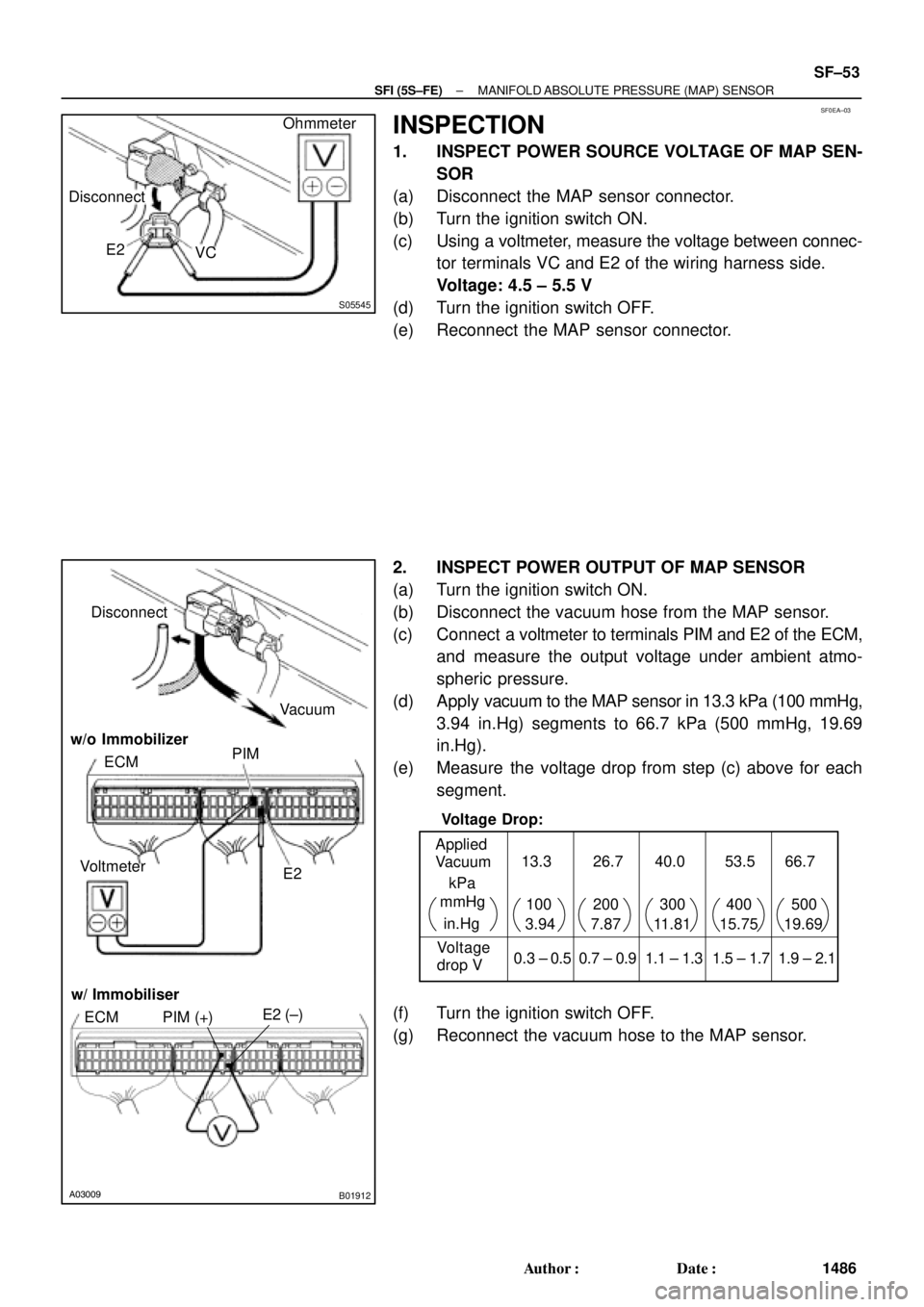
1. INSPECT POWER SOURCE VOLTAGE OF MAP SEN-
SOR
(a) Disconnect the MAP sensor connector.
(b) Turn the ignition switch ON.
(c) Using a voltmeter, measure the voltage between connec-
tor terminals VC and E2 of the wiring harness side.
Voltage: 4.5 ± 5.5 V
(d) Turn the ignition switch OFF.
(e) Reconnect the MAP sensor connector.
2. INSPECT POWER OUTPUT OF MAP SENSOR
(a) Turn the ignition switch ON.
(b) Disconnect the vacuum hose from the MAP sensor.
(c) Connect a voltmeter to terminals PIM and E2 of the ECM,
and measure the output voltage under ambient atmo-
spheric pressure.
(d) Apply vacuum to the MAP sensor in 13.3 kPa (100 mmHg,
3.94 in.Hg) segments to 66.7 kPa (500 mmHg, 19.69
in.Hg).
(e) Measure the voltage drop from step (c) above for each
segment.
(f) Turn the ignition switch OFF.
(g) Reconnect the vacuum hose to the MAP sensor.
Page 3516 of 4592
F01476
Key Unlock Warning Switch
Column Upper Bracket Ignition Switch
Energy Absorbing PlateTransponder Key Coil Key Cylinder Lamp Assembly
Key
Interlock
Solenoid Key Cylinder
Transponder Key
Amplifier
Energy Absorbing Plate
Guide� Energy Absorbing Clip
Energy Absorbing Plate
Energy Absorbing Plate
Guide
� Energy Absorbing Clip Column TubeTilt Lever
Return Spring
� Tapered±Head Bolt Column Upper Tube Turn Signal Bracket
Lower Column Tube AttachmentColumn Tube Support
7 (70, 61 in.´lbf)
19 (195, 14)
N´m (kgf´cm, ft´lbf): Specified torque
� Non±reusable partw/ ENGINE IMMOBILISER SYSTEM:
A/T: SR±10
± STEERINGTILT STEERING COLUMN
2105 Author�: Date�:
Page 3519 of 4592

SR06J±01
W03333
Screw Extractor
W03334
± STEERINGTILT STEERING COLUMN
SR±13
2108 Author�: Date�:
DISASSEMBLY
NOTICE:
When using a vise, do not overtighten it.
1. w/ ENGINE IMMOBILISER SYSTEM:
REMOVE TRANSPONDER KEY COIL WITH KEY CYL-
INDER LAMP ASSEMBLY
Remove the screw.
2. w/ ENGINE IMMOBILISER SYSTEM:
REMOVE KEY CYLINDER LAMP ASSEMBLY
Remove the lamp assembly from the key coil.
3. w/o ENGINE IMMOBILISER SYSTEM:
REMOVE KEY CYLINDER LAMP ASSEMBLY
Remove the screw.
4. REMOVE COLUMN UPPER BRACKET AND COLUMN
UPPER CLAMP
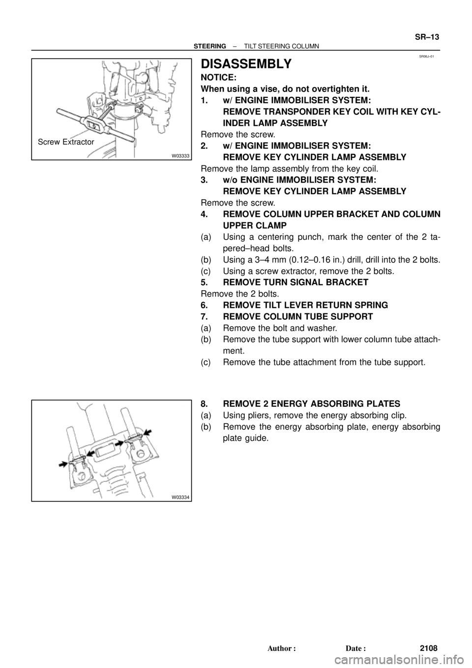
(a) Using a centering punch, mark the center of the 2 ta-
pered±head bolts.
(b) Using a 3±4 mm (0.12±0.16 in.) drill, drill into the 2 bolts.
(c) Using a screw extractor, remove the 2 bolts.
5. REMOVE TURN SIGNAL BRACKET
Remove the 2 bolts.
6. REMOVE TILT LEVER RETURN SPRING
7. REMOVE COLUMN TUBE SUPPORT
(a) Remove the bolt and washer.
(b) Remove the tube support with lower column tube attach-
ment.
(c) Remove the tube attachment from the tube support.
8. REMOVE 2 ENERGY ABSORBING PLATES
(a) Using pliers, remove the energy absorbing clip.
(b) Remove the energy absorbing plate, energy absorbing
plate guide.
Page 3521 of 4592

SR06L±01
W03347
W03337
± STEERINGTILT STEERING COLUMN
SR±15
2110 Author�: Date�:
REASSEMBLY
NOTICE:
When using a vise, do not overtighten it.
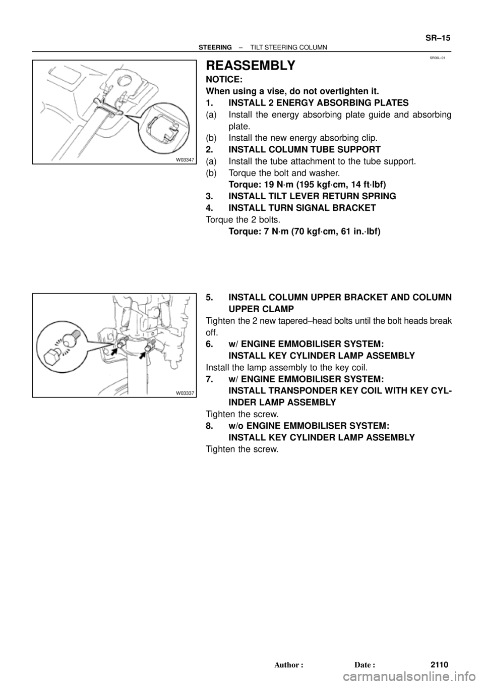
1. INSTALL 2 ENERGY ABSORBING PLATES
(a) Install the energy absorbing plate guide and absorbing
plate.
(b) Install the new energy absorbing clip.
2. INSTALL COLUMN TUBE SUPPORT
(a) Install the tube attachment to the tube support.
(b) Torque the bolt and washer.
Torque: 19 N´m (195 kgf´cm, 14 ft´lbf)
3. INSTALL TILT LEVER RETURN SPRING
4. INSTALL TURN SIGNAL BRACKET
Torque the 2 bolts.
Torque: 7 N´m (70 kgf´cm, 61 in.´lbf)
5. INSTALL COLUMN UPPER BRACKET AND COLUMN
UPPER CLAMP
Tighten the 2 new tapered±head bolts until the bolt heads break
off.
6. w/ ENGINE EMMOBILISER SYSTEM:
INSTALL KEY CYLINDER LAMP ASSEMBLY
Install the lamp assembly to the key coil.
7. w/ ENGINE EMMOBILISER SYSTEM:
INSTALL TRANSPONDER KEY COIL WITH KEY CYL-
INDER LAMP ASSEMBLY
Tighten the screw.
8. w/o ENGINE EMMOBILISER SYSTEM:
INSTALL KEY CYLINDER LAMP ASSEMBLY
Tighten the screw.