Page 3592 of 4592
SA07P±01
W03646
SA±36
± SUSPENSION AND AXLEFRONT SHOCK ABSORBER
1987 Author�: Date�:
INSPECTION
INSPECT SHOCK ABSORBER
Compress and extend the shock absorber rod and check that
there is no abnormal resistance or unusual operation sound.
NOTICE:
When discarding the shock absorber, see DISPOSAL on
page SA±37.
Page 3593 of 4592
SA0II±01
W03648
± SUSPENSION AND AXLEFRONT SHOCK ABSORBER
SA±37
1988 Author�: Date�:
DISPOSAL
1. FULLY EXTEND SHOCK ABSORBER ROD
2. DRILL HOLE TO REMOVE GAS FROM CYLINDER
Using a drill, make a hole in the cylinder as shown in the illustra-
tion to remove the gas inside.
CAUTION:
The discharged gas is harmless, but be careful of chips
which may fly up when drilling.
Page 3594 of 4592

SA07R±01
W03200
SST
W03201
W03199
SST SA±38
± SUSPENSION AND AXLEFRONT SHOCK ABSORBER
1989 Author�: Date�:
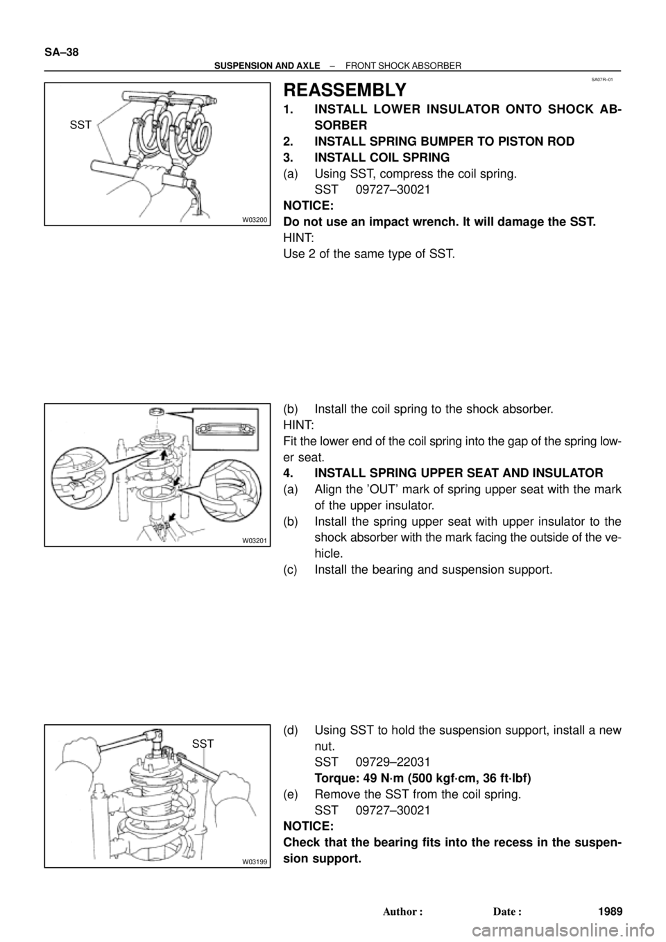
REASSEMBLY
1. INSTALL LOWER INSULATOR ONTO SHOCK AB-
SORBER
2. INSTALL SPRING BUMPER TO PISTON ROD
3. INSTALL COIL SPRING
(a) Using SST, compress the coil spring.
SST 09727±30021
NOTICE:
Do not use an impact wrench. It will damage the SST.
HINT:
Use 2 of the same type of SST.
(b) Install the coil spring to the shock absorber.
HINT:
Fit the lower end of the coil spring into the gap of the spring low-
er seat.
4. INSTALL SPRING UPPER SEAT AND INSULATOR
(a) Align the 'OUT' mark of spring upper seat with the mark
of the upper insulator.
(b) Install the spring upper seat with upper insulator to the
shock absorber with the mark facing the outside of the ve-
hicle.
(c) Install the bearing and suspension support.
(d) Using SST to hold the suspension support, install a new
nut.
SST 09729±22031
Torque: 49 N´m (500 kgf´cm, 36 ft´lbf)
(e) Remove the SST from the coil spring.
SST 09727±30021
NOTICE:
Check that the bearing fits into the recess in the suspen-
sion support.
Page 3595 of 4592
SA07S±01
± SUSPENSION AND AXLEFRONT SHOCK ABSORBER
SA±39
1990 Author�: Date�:
INSTALLATION
Installation is in the reverse order of removal (See page SA±34).
AFTER INSTALLATION, CHECK FRONT WHEEL ALIGNMENT (See page SA±4)
Page 3596 of 4592
SA07T±04
F06530
Suspension Support
Spring Bumper
Link Stabilizer Bar
Shock
Absorber
ABS Speed Sensor
Wire Harness ClampFront Drive Shaft with Coil SpringUpper Seat Bearing
Lower
Insulator
Lower Suspension Arm Lower Suspension
Bushing StopperBrake CaliperInsulator UpperSpring Support No. 2Suspension
Shock Absorber
Coil Spring
Tie Rod End
� Dust
Deflector
� Cotter Pin
� Cotter Pin� Cotter
Pin
Lower Ball jointDisc
Lock Cap ABS Speed Sensor
N´m (kgf´cm, ft´lbf): Specified torque
� Non±reusable part�
80 (820, 59)49 (500, 36)
39 (400, 29)
211 (2,150, 156)
107 (1,090, 79)
29 (300, 22)
123 (1,250, 90)49 (500, 36)
8.0 (82, 71 in.´lbf)
294 (3,000, 217)
206 (2,100, 152)
206 (2,100, 152)
206 (2,100, 152)
127 (1,300, 94)
127 (1,300, 94)
SA±40
± SUSPENSION AND AXLEFRONT LOWER SUSPENSION ARM
1991 Author�: Date�:
FRONT LOWER SUSPENSION ARM
COMPONENTS
Page 3599 of 4592
SA07X±05
F06530
Suspension Support
Spring Bumper
Link Stabilizer Bar
Shock
Absorber
ABS Speed Sensor
Wire Harness ClampFront Drive Shaft with Coil SpringUpper Seat Bearing
Lower
Insulator
Lower Suspension Arm Lower Suspension
Bushing StopperBrake CaliperInsulator UpperSpring Support No. 2Suspension
Shock Absorber
Coil Spring
Tie Rod End
� Dust
Deflector
� Cotter Pin
� Cotter Pin� Cotter
Pin
Lower Ball jointDisc
Lock Cap ABS Speed Sensor
N´m (kgf´cm, ft´lbf): Specified torque
� Non±reusable part�
80 (820, 59)49 (500, 36)
39 (400, 29)
211 (2,150, 156)
107 (1,090, 79)
29 (300, 22)
123 (1,250, 90)49 (500, 36)
8.0 (82, 71 in.´lbf)
294 (3,000, 217)
206 (2,100, 152)
206 (2,100, 152)
206 (2,100, 152)
127 (1,300, 94)
127 (1,300, 94)
± SUSPENSION AND AXLEFRONT LOWER BALL JOINT
SA±43
1994 Author�: Date�:
FRONT LOWER BALL JOINT
COMPONENTS
Page 3602 of 4592
SA080±01
R08850
R08861
SST
SST SA±46
± SUSPENSION AND AXLEFRONT LOWER BALL JOINT
1997 Author�: Date�:
INSTALLATION
1. INSTALL LOWER BALL JOINT
(a) Install the lower ball joint and tighten the nut.
Torque:123 N´m (1,250 kgf´cm, 90 ft´lbf)
(b) Install a new cotter pin.
2. INSTALL NEW DUST DEFLECTOR
Using SST and a hammer, install a new dust deflector.
SST 09316±60011 (09316±00011, 09316±00041),
09608±32010
HINT:
Align the holes for the ABS speed sensor in the dust deflector
and steering knuckle.
3. INSTALL STEERING KNUCKLE WITH AXLE HUB
(See page SA±13)
4. CHECK ABS SPEED SENSOR SIGNAL (See page
DI±493 or DI±539) AND FRONT WHEEL ALIGNMENT
(See page SA±4)
Page 3607 of 4592
SA085±01
W03210
DRUM BRAKE
Flexible Hose
Rear Axle Hub
� O±Ring
Hub Bolt
Brake Drum
Brake Caliper No.2 Lower
Suspension Arm
Rear Axle
Carrier
No.1 Lower
Suspension Arm
� O±Ring
Hub Bolt
Rear Axle HubDisc ABS
Speed Sensor
Strut Rod
N´m (kgf´cm, ft´lbf)
� Non±reusable part: Specified torque
181 (1,850, 134)
47 (475, 134)
80 (820, 59)
113 (1,150, 83)
29 (300, 22)
80 (820, 59)
Reused Nut : 196 (2,000, 145)
New Nut : 255 (2,600, 188)
8.0 (82, 71 in.´lbf)
± SUSPENSION AND AXLEREAR AXLE HUB
SA±51
2002 Author�: Date�:
REAR AXLE HUB
COMPONENTS