Page 3557 of 4592

SA077±01
± SUSPENSION AND AXLETROUBLESHOOTING
SA±1
1952 Author�: Date�:
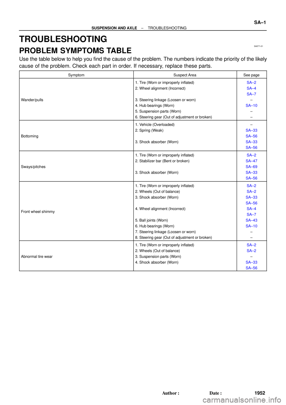
TROUBLESHOOTING
PROBLEM SYMPTOMS TABLE
Use the table below to help you find the cause of the problem. The numbers indicate the priority of the likely
cause of the problem. Check each part in order. If necessary, replace these parts.
SymptomSuspect AreaSee page
Wander/pulls
1. Tire (Worn or improperly inflated)
2. Wheel alignment (Incorrect)
3. Steering linkage (Loosen or worn)
4. Hub bearings (Worn)
5. Suspension parts (Worn)
6. Steering gear (Out of adjustment or broken)SA±2
SA±4
SA±7
±
SA±10
±
±
Bottoming
1. Vehicle (Overloaded)
2. Spring (Weak)
3. Shock absorber (Worn)±
SA±33
SA±56
SA±33
SA±56
Sways/pitches
1. Tire (Worn or improperly inflated)
2. Stabilizer bar (Bent or broken)
3. Shock absorber (Worn)SA±2
SA±47
SA±69
SA±33
SA±56
Front wheel shimmy
1. Tire (Worn or improperly inflated)
2. Wheels (Out of balance)
3. Shock absorber (Worn)
4. Wheel alignment (Incorrect)
5. Ball joints (Worn)
6. Hub bearings (Worn)
7. Steering linkage (Loosen or worn)
8. Steering gear (Out of adjustment or broken)SA±2
SA±2
SA±33
SA±56
SA±4
SA±7
SA±43
SA±10
±
±
Abnormal tire wear
1. Tire (Worn or improperly inflated)
2. Wheels (Out of balance)
3. Suspension parts (Worn)
4. Shock absorber (Worn)SA±2
SA±2
±
SA±33
SA±56
Page 3559 of 4592
W03084
± SUSPENSION AND AXLETIRE AND WHEEL
SA±3
1954 Author�: Date�:
4. CHECK WHEEL BEARING LOOSENESS
(a) Check the backlash in the bearing shaft direction.
Maximum: 0.05 mm (0.0020 in.)
(b) Check the axle hub deviation.
Maximum: 0.05 mm (0.0020 in.)
5. CHECK FRONT SUSPENSION FOR LOOSENESS
6. CHECK STEERING LINKAGE FOR LOOSENESS
7. CHECK BALL JOINT FOR LOOSENESS
8. CHECK SHOCK ABSORBER WORKS PROPERLY
�Check for oil leaks
�Check mounting bushings for wear
�Check front and rear of the vehicle for bounce
Page 3561 of 4592

W03086
F02267
1
2
F01195
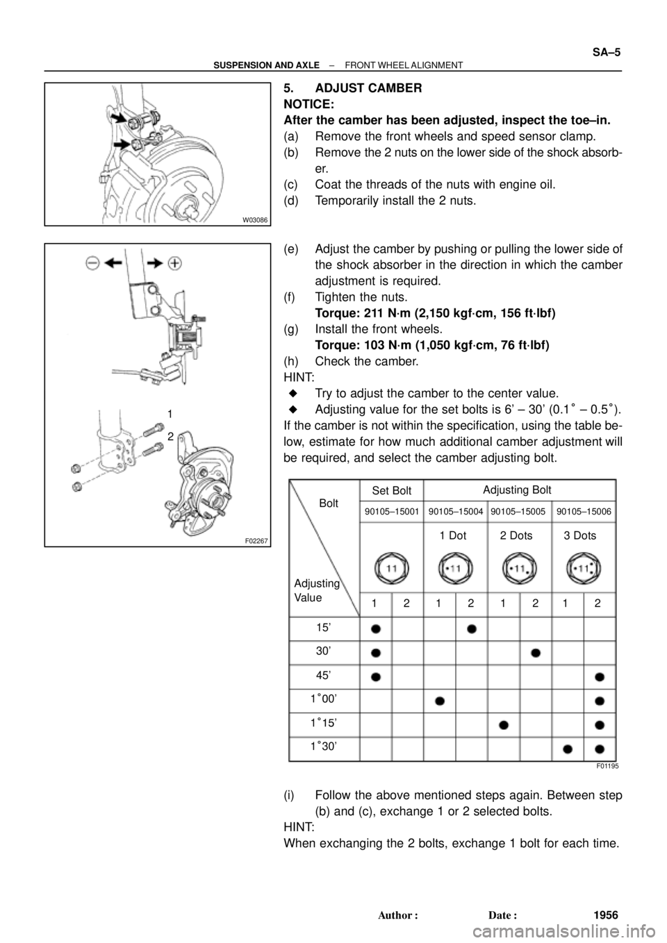
Bolt
Adjusting
ValueSet Bolt
15'
30'Adjusting Bolt90105±15001 90105±15004 90105±15005 90105±15006
45'
1°00'
1°15'
1°30'121212121 Dot 2 Dots 3 Dots
± SUSPENSION AND AXLEFRONT WHEEL ALIGNMENT
SA±5
1956 Author�: Date�:
5. ADJUST CAMBER
NOTICE:
After the camber has been adjusted, inspect the toe±in.
(a) Remove the front wheels and speed sensor clamp.
(b) Remove the 2 nuts on the lower side of the shock absorb-
er.
(c) Coat the threads of the nuts with engine oil.
(d) Temporarily install the 2 nuts.
(e) Adjust the camber by pushing or pulling the lower side of
the shock absorber in the direction in which the camber
adjustment is required.
(f) Tighten the nuts.
Torque: 211 N´m (2,150 kgf´cm, 156 ft´lbf)
(g) Install the front wheels.
Torque: 103 N´m (1,050 kgf´cm, 76 ft´lbf)
(h) Check the camber.
HINT:
�Try to adjust the camber to the center value.
�Adjusting value for the set bolts is 6' ± 30' (0.1° ± 0.5°).
If the camber is not within the specification, using the table be-
low, estimate for how much additional camber adjustment will
be required, and select the camber adjusting bolt.
(i) Follow the above mentioned steps again. Between step
(b) and (c), exchange 1 or 2 selected bolts.
HINT:
When exchanging the 2 bolts, exchange 1 bolt for each time.
Page 3565 of 4592
SA07B±01
W03092
Front Shock Absorber
Tie Rod End
Front Drive Shaft
Brake Caliper
ABS Speed Sensor
Lower Suspension ArmLock Cap
� Snap Ring
� Dust DeflectorSteering Knuckle
Dust Cover
�Bearing
Lower Ball JointAxle Hub
127 (1,300, 94)
294 (3,000, 217)
107 (1,090,79)
8.0 (82, 71 in.´lbf)
123 (1,250, 90)� Cotter pin� Cotter pin� Cotter pin Hub Bolt
Disc
N´m (kgf´cm, ft´lbf) : Specified torque
� Non±reusable part
211 (2,150, 156)
49 (500, 36)
8.3 (85, 74 in.´lbf)
± SUSPENSION AND AXLEFRONT AXLE HUB
SA±9
1960 Author�: Date�:
FRONT AXLE HUB
COMPONENTS
Page 3566 of 4592

SA07C±01
W03084W03084
W03093
W03139
W03094
SST
SA±10
± SUSPENSION AND AXLEFRONT AXLE HUB
1961 Author�: Date�:
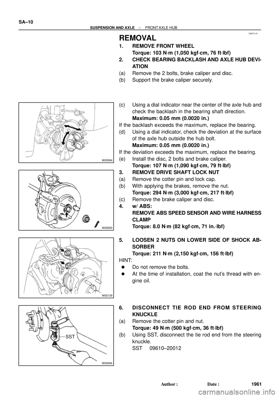
REMOVAL
1. REMOVE FRONT WHEEL
Torque: 103 N´m (1,050 kgf´cm, 76 ft´lbf)
2. CHECK BEARING BACKLASH AND AXLE HUB DEVI-
ATION
(a) Remove the 2 bolts, brake caliper and disc.
(b) Support the brake caliper securely.
(c) Using a dial indicator near the center of the axle hub and
check the backlash in the bearing shaft direction.
Maximum: 0.05 mm (0.0020 in.)
If the backlash exceeds the maximum, replace the bearing.
(d) Using a dial indicator, check the deviation at the surface
of the axle hub outside the hub bolt.
Maximum: 0.05 mm (0.0020 in.)
If the deviation exceeds the maximum, replace the bearing.
(e) Install the disc, 2 bolts and brake caliper.
Torque: 107 N´m (1,090 kgf´cm, 79 ft´lbf)
3. REMOVE DRIVE SHAFT LOCK NUT
(a) Remove the cotter pin and lock cap.
(b) With applying the brakes, remove the nut.
Torque: 294 N´m (3,000 kgf´cm, 217 ft´lbf)
(c) Remove the brake caliper and disc.
4. w/ ABS:
REMOVE ABS SPEED SENSOR AND WIRE HARNESS
CLAMP
Torque: 8.0 N´m (82 kgf´cm, 71 in.´lbf)
5. LOOSEN 2 NUTS ON LOWER SIDE OF SHOCK AB-
SORBER
Torque: 211 N´m (2,150 kgf´cm, 156 ft´lbf)
HINT:
�Do not remove the bolts.
�At the time of installation, coat the nut's thread with en-
gine oil.
6. DISCONNECT TIE ROD END FROM STEERING
KNUCKLE
(a) Remove the cotter pin and nut.
Torque: 49 N´m (500 kgf´cm, 36 ft´lbf)
(b) Using SST, disconnect the tie rod end from the steering
knuckle.
SST 09610±20012
Page 3567 of 4592
W03095
± SUSPENSION AND AXLEFRONT AXLE HUB
SA±11
1962 Author�: Date�:
7. DISCONNECT LOWER BALL JOINT FROM LOWER
ARM
Remove the 2 nuts and bolt.
Torque: 127 N´m (1,300 kgf´cm, 94 ft´lbf)
8. REMOVE STEERING KNUCKLE WITH AXLE HUB
(a) Remove the 2 bolts on the lower side of the shock absorb-
er.
(b) Remove the steering knuckle with the axle hub.
NOTICE:
Be careful not to damage the oil seal with drive shaft.
Page 3569 of 4592
SA07E±01
R00792
SST
R08860
SST
SST
Z19236
SST
SST
± SUSPENSION AND AXLEFRONT AXLE HUB
SA±13
1964 Author�: Date�:
REASSEMBLY
1. INSTALL BEARING
(a) Using SST and a press, install a new bearing to the steer-
ing knuckle.
SST 09608±32010
(b) Using snap ring pliers, install a new snap ring.
2. INSTALL DUST COVER
Place the dust cover and using a torx wrench (T30), torque the
4 bolts.
Torque: 8.3 N´m (85 kgf´cm, 74 in.´lbf)
3. INSTALL FRONT AXLE HUB
Using SST and a press, install the axle hub.
SST 09310±35010, 09608±32010
4. INSTALL LOWER BALL JOINT
(a) Install the lower ball joint and torque the nut.
Torque: 123 N´m (1,250 kgf´cm, 90 ft´lbf)
(b) Install a new cotter pin.
5. INSTALL DUST DEFLECTOR
Using SST and a hammer, install a new dust deflector.
SST 09316±60011 (09316±00011, 09316±00041),
09608±32010
HINT:
Align the holes for the ABS speed sensor in the dust deflector
and steering knuckle.
Page 3570 of 4592
SA07F±01
SA±14
± SUSPENSION AND AXLEFRONT AXLE HUB
1965 Author�: Date�:
INSTALLATION
Installation is in the reverse order of removal (See page SA±10).
AFTER INSTALLATION, CHECK ABS SPEED SENSOR SIGNAL (See page DI±493 or DI±539) AND
FRONT WHEEL ALIGNMENT (See page SA±4)