Page 3618 of 4592
SA08F±01
SA±62
± SUSPENSION AND AXLEREAR SHOCK ABSORBER
2013 Author�: Date�:
INSTALLATION
Installation is in the reverse order of removal (See page SA±57).
AFTER INSTALLATION, CHECK REAR WHEEL ALIGNMENT (See page SA±7)
Page 3629 of 4592

F08080
Front:
Rear:SA1DP±03
Z03382
± SUSPENSION AND AXLEFRONT WHEEL ALIGNMENT
SA±1
508 Author�: Date�:
FRONT WHEEL ALIGNMENT
INSPECTION
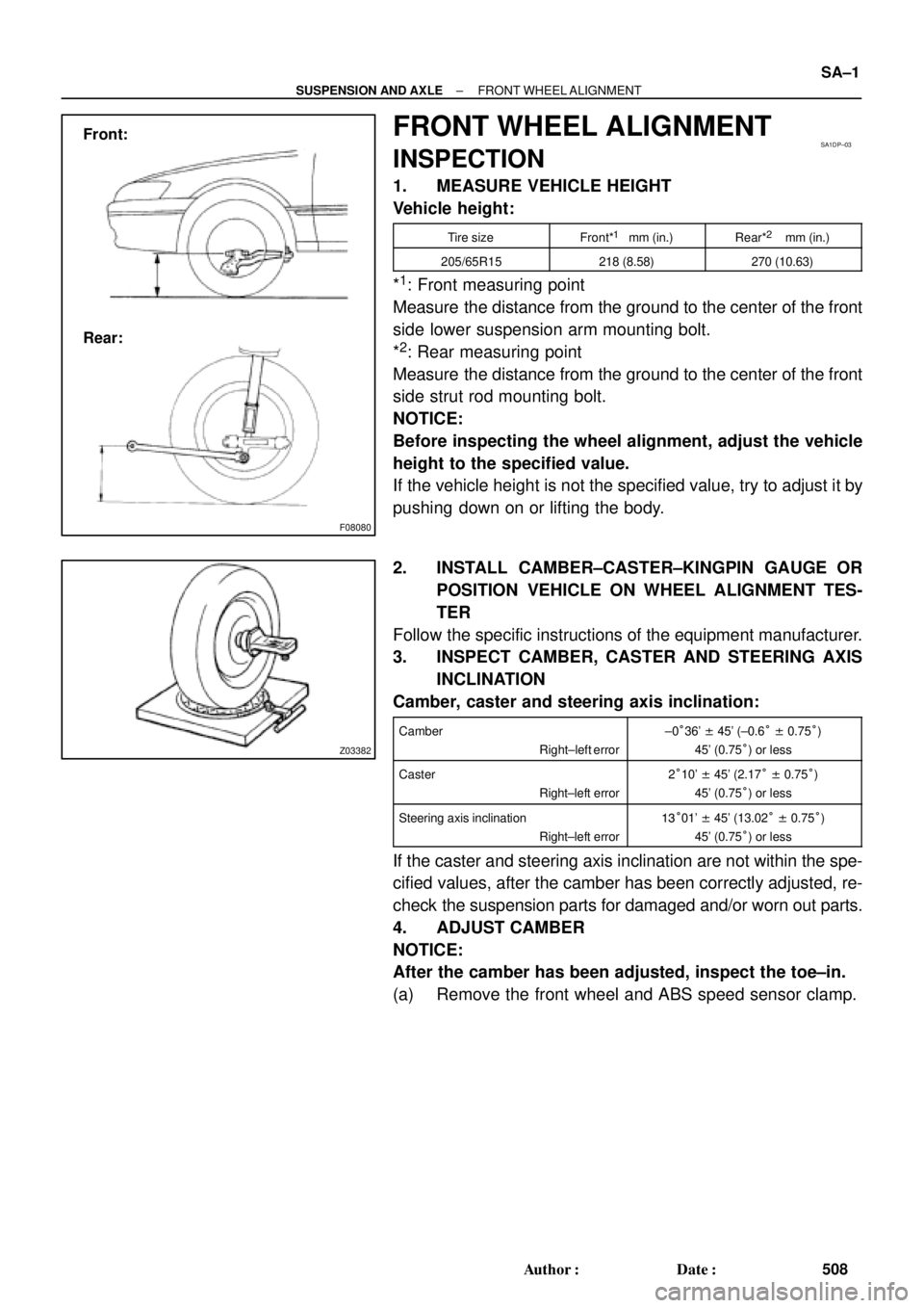
1. MEASURE VEHICLE HEIGHT
Vehicle height:
Tire sizeFront*1 mm (in.)Rear*2 mm (in.)
205/65R15218 (8.58)270 (10.63)
*1: Front measuring point
Measure the distance from the ground to the center of the front
side lower suspension arm mounting bolt.
*
2: Rear measuring point
Measure the distance from the ground to the center of the front
side strut rod mounting bolt.
NOTICE:
Before inspecting the wheel alignment, adjust the vehicle
height to the specified value.
If the vehicle height is not the specified value, try to adjust it by
pushing down on or lifting the body.
2. INSTALL CAMBER±CASTER±KINGPIN GAUGE OR
POSITION VEHICLE ON WHEEL ALIGNMENT TES-
TER
Follow the specific instructions of the equipment manufacturer.
3. INSPECT CAMBER, CASTER AND STEERING AXIS
INCLINATION
Camber, caster and steering axis inclination:
Camber
Right±left error±0°36' ± 45' (±0.6° ± 0.75°)
45' (0.75°) or less
Caster
Right±left error2°10' ± 45' (2.17° ± 0.75°)
45' (0.75°) or less
Steering axis inclination
Right±left error13°01' ± 45' (13.02° ± 0.75°)
45' (0.75°) or less
If the caster and steering axis inclination are not within the spe-
cified values, after the camber has been correctly adjusted, re-
check the suspension parts for damaged and/or worn out parts.
4. ADJUST CAMBER
NOTICE:
After the camber has been adjusted, inspect the toe±in.
(a) Remove the front wheel and ABS speed sensor clamp.
Page 3630 of 4592

F04031
F04048
1
2
F01195
Bolt
Adjusting
ValueSet Bolt
15'
30'Adjusting Bolt90105±15001 90105±15004 90105±15005 90105±15006
45'
1°00'
1°15'
1°30'121212121 Dot
2 Dots3 Dots SA±2
± SUSPENSION AND AXLEFRONT WHEEL ALIGNMENT
509 Author�: Date�:
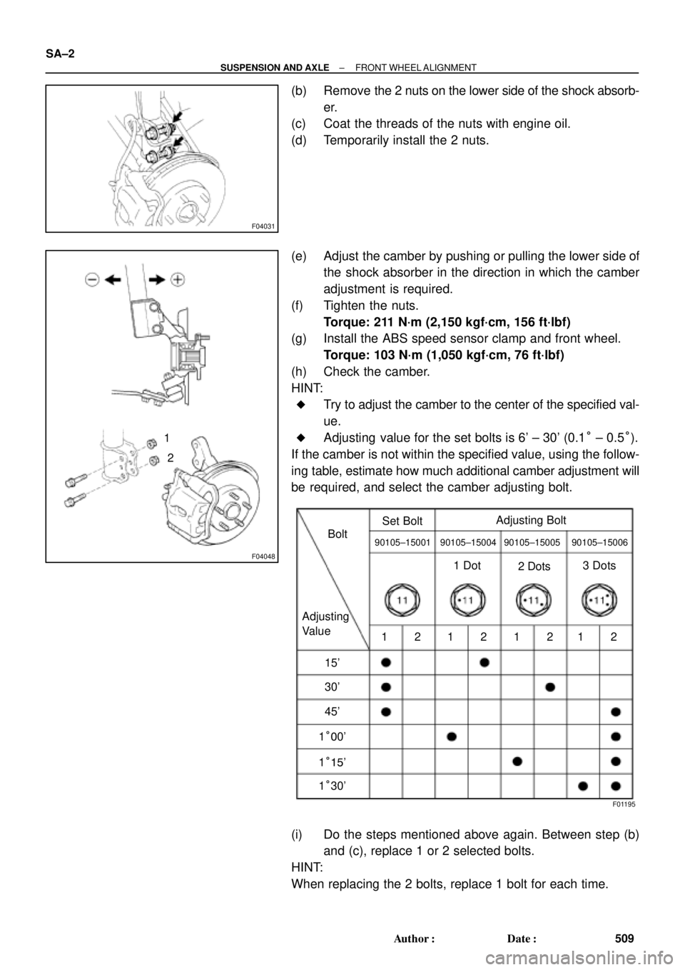
(b) Remove the 2 nuts on the lower side of the shock absorb-
er.
(c) Coat the threads of the nuts with engine oil.
(d) Temporarily install the 2 nuts.
(e) Adjust the camber by pushing or pulling the lower side of
the shock absorber in the direction in which the camber
adjustment is required.
(f) Tighten the nuts.
Torque: 211 N´m (2,150 kgf´cm, 156 ft´lbf)
(g) Install the ABS speed sensor clamp and front wheel.
Torque: 103 N´m (1,050 kgf´cm, 76 ft´lbf)
(h) Check the camber.
HINT:
�Try to adjust the camber to the center of the specified val-
ue.
�Adjusting value for the set bolts is 6' ± 30' (0.1° ± 0.5°).
If the camber is not within the specified value, using the follow-
ing table, estimate how much additional camber adjustment will
be required, and select the camber adjusting bolt.
(i) Do the steps mentioned above again. Between step (b)
and (c), replace 1 or 2 selected bolts.
HINT:
When replacing the 2 bolts, replace 1 bolt for each time.
Page 3632 of 4592
SA07B±05
F08042
Front Shock Absorber
Tie Rod End
Front Drive Shaft
Brake Caliper
ABS Speed Sensor
Lower Suspension ArmLock Cap
� Snap Ring
� Dust DeflectorSteering Knuckle
Dust Cover
�Bearing
Lower Ball JointAxle Hub � Cotter pin� Cotter pin� Cotter pin Hub Bolt
Disc
N´m (kgf´cm, ft´lbf) : Specified torque
� Non±reusable part
127 (1,300, 94)
107 (1,090, 79)
49 (500, 36)
8.3 (85, 74 in.´lbf)
123 (1,250, 90)
211 (2,150, 156)
294 (3,000, 217)
8.0 (82, 71 in.´lbf)
SA±4
± SUSPENSION AND AXLEFRONT AXLE HUB
511 Author�: Date�:
FRONT AXLE HUB
COMPONENTS
Page 3634 of 4592

SA1JR±01
FA1535
SST
W03093
W03094
SST
W03095
SA±6
± SUSPENSION AND AXLEFRONT DRIVE SHAFT
REMOVAL
NOTICE:
�The hub bearing could be damaged if it is subjected
to the vehicle weight, such as when moving the ve-
hicle with the drive shaft removed.
Therefore, if it is absolutely necessary to place the ve-
hicle weight on the hub bearing, first support it with
SST.
SST 09608±16042 (09608±02021, 09608±02041)
�After disconnecting the drive shaft from the axle hub,
work carefully so as not to damage the ABS speed
sensor rotor serration on the drive shaft.
1. REMOVE FRONT WHEEL AND FRONT FENDER
APRON SEAL
2. DRAIN ATF
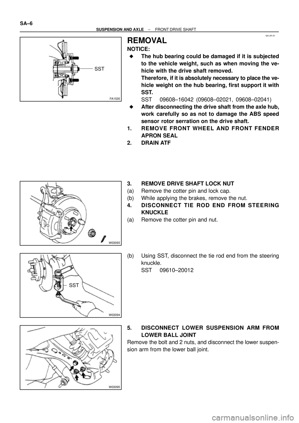
3. REMOVE DRIVE SHAFT LOCK NUT
(a) Remove the cotter pin and lock cap.
(b) While applying the brakes, remove the nut.
4. DISCONNECT TIE ROD END FROM STEERING
KNUCKLE
(a) Remove the cotter pin and nut.
(b) Using SST, disconnect the tie rod end from the steering
knuckle.
SST 09610±20012
5. DISCONNECT LOWER SUSPENSION ARM FROM
LOWER BALL JOINT
Remove the bolt and 2 nuts, and disconnect the lower suspen-
sion arm from the lower ball joint.
Page 3635 of 4592
W03142
R00647
LH:
W03144
RH:
± SUSPENSION AND AXLEFRONT DRIVE SHAFT
SA±7
6. DISCONNECT DRIVE SHAFT FROM AXLE HUB
(a) Using a plastic hammer, disconnect the drive shaft from
the axle hub.
NOTICE:
Be careful not to damage the boot and ABS speed sensor
rotor.
(b) Push the front axle hub toward the outside of the vehicle,
and separate the drive shaft from the axle hub.
7. REMOVE LH DRIVE SHAFT
(a) Using a hub nut wrench and wooden block or an equiva-
lent, remove the drive shaft.
(b) Using a screwdriver, remove the snap ring from the in-
board joint shaft.
NOTICE:
Be careful not to damage the boot and ABS speed sensor
rotor.
8. REMOVE RH DRIVE SHAFT
(a) Remove the bearing lock bolt.
(b) Using pliers, remove the snap ring and drive shaft.
NOTICE:
Be careful not to damage the boot and ABS speed sensor
rotor.
Page 3638 of 4592
F06452
SA±10
± SUSPENSION AND AXLEFRONT DRIVE SHAFT
8. REMOVE NO. 2 DUST DEFLECTOR
(a) Mount the outboard joint shaft in a soft jaw vise.
(b) Using a screwdriver and hammer, remove the No. 2 dust
deflector.
NOTICE:
Be careful not to damage the ABS speed sensor rotor.
Page 3642 of 4592

SA1EC±02
SA±14
± SUSPENSION AND AXLEFRONT DRIVE SHAFT
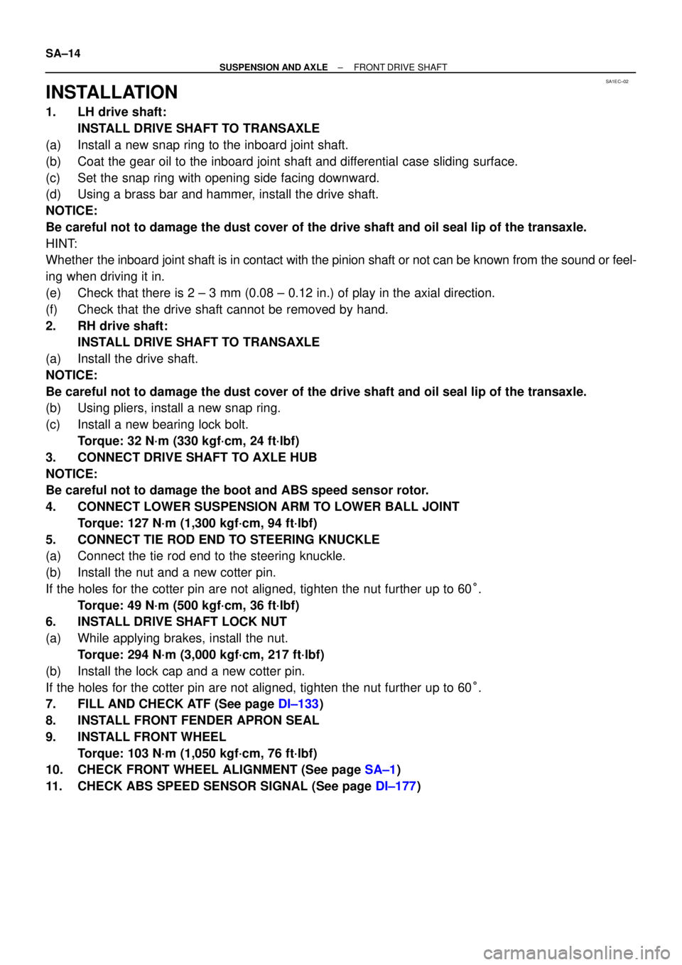
INSTALLATION
1. LH drive shaft:
INSTALL DRIVE SHAFT TO TRANSAXLE
(a) Install a new snap ring to the inboard joint shaft.
(b) Coat the gear oil to the inboard joint shaft and differential case sliding surface.
(c) Set the snap ring with opening side facing downward.
(d) Using a brass bar and hammer, install the drive shaft.
NOTICE:
Be careful not to damage the dust cover of the drive shaft and oil seal lip of the transaxle.
HINT:
Whether the inboard joint shaft is in contact with the pinion shaft or not can be known from the sound or feel-
ing when driving it in.
(e) Check that there is 2 ± 3 mm (0.08 ± 0.12 in.) of play in the axial direction.
(f) Check that the drive shaft cannot be removed by hand.
2. RH drive shaft:
INSTALL DRIVE SHAFT TO TRANSAXLE
(a) Install the drive shaft.
NOTICE:
Be careful not to damage the dust cover of the drive shaft and oil seal lip of the transaxle.
(b) Using pliers, install a new snap ring.
(c) Install a new bearing lock bolt.
Torque: 32 N´m (330 kgf´cm, 24 ft´lbf)
3. CONNECT DRIVE SHAFT TO AXLE HUB
NOTICE:
Be careful not to damage the boot and ABS speed sensor rotor.
4. CONNECT LOWER SUSPENSION ARM TO LOWER BALL JOINT
Torque: 127 N´m (1,300 kgf´cm, 94 ft´lbf)
5. CONNECT TIE ROD END TO STEERING KNUCKLE
(a) Connect the tie rod end to the steering knuckle.
(b) Install the nut and a new cotter pin.
If the holes for the cotter pin are not aligned, tighten the nut further up to 60°.
Torque: 49 N´m (500 kgf´cm, 36 ft´lbf)
6. INSTALL DRIVE SHAFT LOCK NUT
(a) While applying brakes, install the nut.
Torque: 294 N´m (3,000 kgf´cm, 217 ft´lbf)
(b) Install the lock cap and a new cotter pin.
If the holes for the cotter pin are not aligned, tighten the nut further up to 60°.
7. FILL AND CHECK ATF (See page DI±133)
8. INSTALL FRONT FENDER APRON SEAL
9. INSTALL FRONT WHEEL
Torque: 103 N´m (1,050 kgf´cm, 76 ft´lbf)
10. CHECK FRONT WHEEL ALIGNMENT (See page SA±1)
11. CHECK ABS SPEED SENSOR SIGNAL (See page DI±177)