Page 3789 of 4592

READINESS MONITOR DRIVE PATTERNS ± EG003-02 RevisedMarch 29, 2002
Page 19 of 23
DRIVE PATTERN NO. 8: EVAP Monitor (For Prius)
Idling
IG SW off
Soak
(1a)15 min
(When the Readiness Monitor or
DTC is set, this test is complete.)
(2a)
50 ± 65 mph
(80 ± 104 km/h)
Cold Soak Preconditions
The monitor will not run unless:
�MIL is OFF.
�Altitude is 7800 feet (2400 m) or less.
IMPORTANT:
A cold soak must be performed prior to conducting the drive pattern to complete the
Internal Pressure Readiness Monitor.
Cold Soak Procedure
1a. Let the vehicle cold soak for 8 hours or until the difference between IAT (Intake
Air) and ECT (Coolant Temp) is less than 13�F (7�C).
�Example 1
�ECT (Coolant Temp) = 75�F (24�C).
�IAT (Intake Air) = 60�F (16�C).
�Difference between ECT (Coolant Temp) and IAT (Intake Air) is 15�F (8�C).
%The monitor will not run because the difference between ECT (Coolant
Temp) and IAT (Intake Air) is greater than 13�F (7�C).
�Example 2
�ECT (Coolant Temp) = 70�F (21�C).
�IAT (Intake Air) = 68�F (20�C).
�Difference between ECT (Coolant Temp) and IAT (Intake Air) is 2�F (1�C).
%The monitor will run because the difference between ECT (Coolant Temp)
and IAT (Intake Air) is less than 13�F (7�C).
Readiness
Monitor
Drive
Patterns:
EVAP
Monitors
(Continued)
Page 3790 of 4592

READINESS MONITOR DRIVE PATTERNS ± EG003-02 RevisedMarch 29, 2002
Page 20 of 23
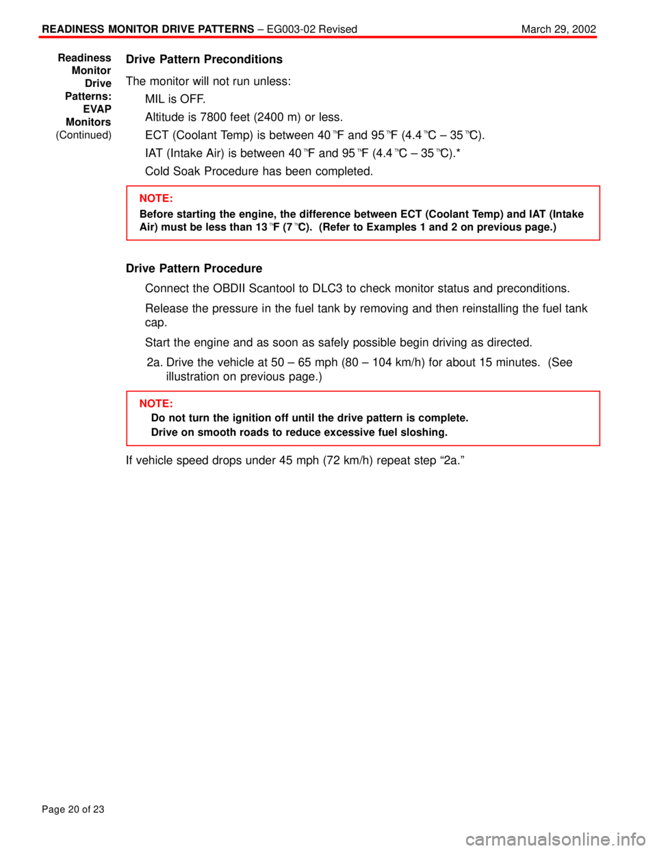
Drive Pattern Preconditions
The monitor will not run unless:
�MIL is OFF.
�Altitude is 7800 feet (2400 m) or less.
�ECT (Coolant Temp) is between 40�F and 95�F (4.4�C ± 35�C).
�IAT (Intake Air) is between 40�F and 95�F (4.4�C ± 35�C).*
�Cold Soak Procedure has been completed.
NOTE:
Before starting the engine, the difference between ECT (Coolant Temp) and IAT (Intake
Air) must be less than 13�F (7�C). (Refer to Examples 1 and 2 on previous page.)
Drive Pattern Procedure
�Connect the OBDII Scantool to DLC3 to check monitor status and preconditions.
�Release the pressure in the fuel tank by removing and then reinstalling the fuel tank
cap.
�Start the engine and as soon as safely possible begin driving as directed.
2a. Drive the vehicle at 50 ± 65 mph (80 ± 104 km/h) for about 15 minutes. (See
illustration on previous page.)
NOTE:
�Do not turn the ignition off until the drive pattern is complete.
�Drive on smooth roads to reduce excessive fuel sloshing.
If vehicle speed drops under 45 mph (72 km/h) repeat step ª2a.º
Readiness
Monitor
Drive
Patterns:
EVAP
Monitors
(Continued)
Page 3815 of 4592

M.I.L. ªONº P0440, P0441 & P0446 ± EG013-02July 12, 2002
Page 2 of 5
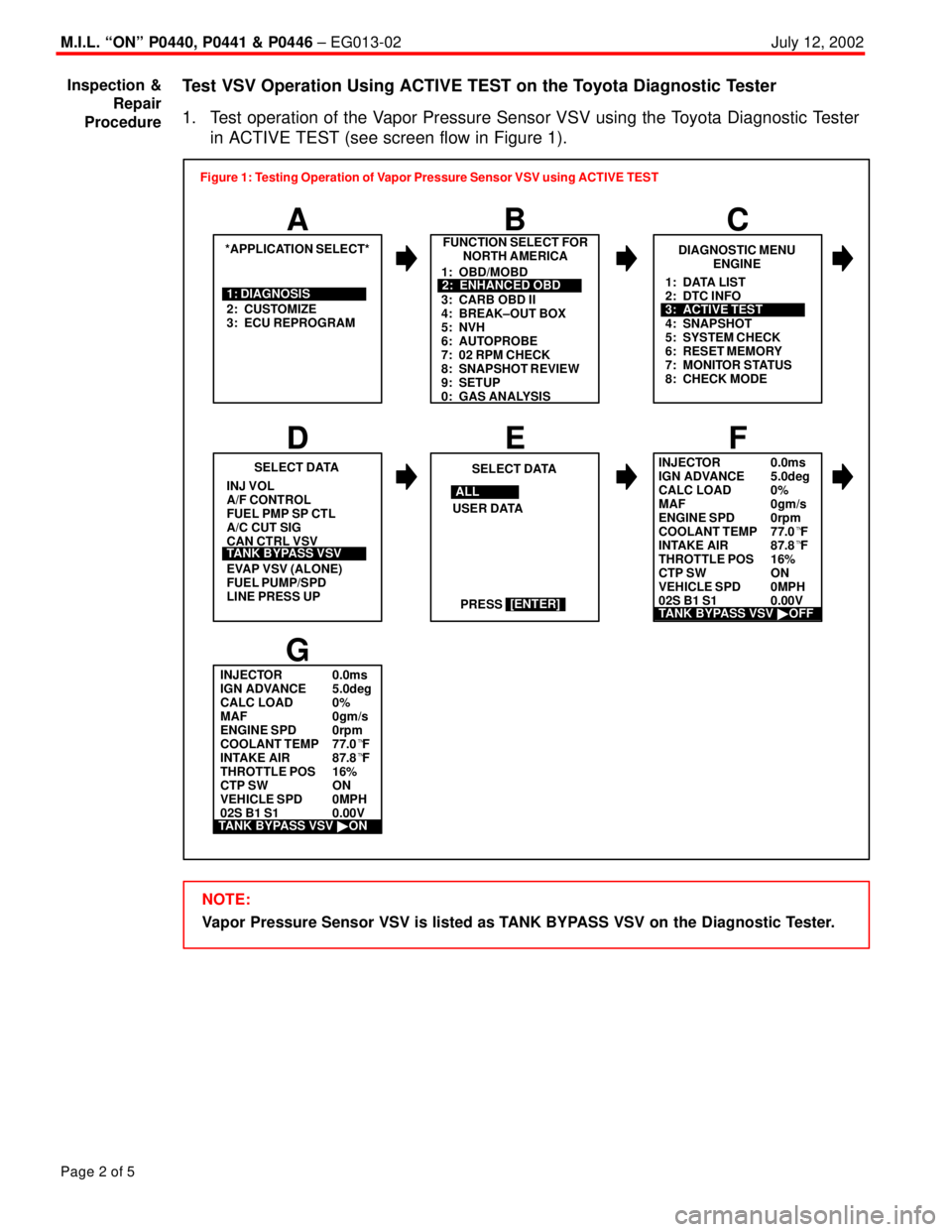
Test VSV Operation Using ACTIVE TEST on the Toyota Diagnostic Tester
1. Test operation of the Vapor Pressure Sensor VSV using the Toyota Diagnostic Tester
in ACTIVE TEST (see screen flow in Figure 1).
INJECTOR 0.0ms
IGN ADVANCE 5.0deg
CALC LOAD 0%
MAF 0gm/s
ENGINE SPD 0rpm
COOLANT TEMP 77.0�F
INTAKE AIR 87.8�F
THROTTLE POS 16%
CTP SW ON
VEHICLE SPD 0MPH
02S B1 S1 0.00V
2: CUSTOMIZE
3: ECU REPROGRAMFUNCTION SELECT FOR
NORTH AMERICA
B
*APPLICATION SELECT*
A
1: DIAGNOSISDIAGNOSTIC MENU
ENGINE
C
PRESS INJ VOL
A/F CONTROL
FUEL PMP SP CTL
A/C CUT SIG
CAN CTRL VSV
EVAP VSV (ALONE)
FUEL PUMP/SPD
LINE PRESS UPSELECT DATA
E
SELECT DATA
D
TANK BYPASS VSVUSER DATA
[ENTER]
F
G
TANK BYPASS VSV �OFF
1: OBD/MOBD
3: CARB OBD II
4: BREAK±OUT BOX
5: NVH
6: AUTOPROBE
7: 02 RPM CHECK
8: SNAPSHOT REVIEW
9: SETUP
0: GAS ANALYSIS2: ENHANCED OBD1: DATA LIST
2: DTC INFO
4: SNAPSHOT
5: SYSTEM CHECK
6: RESET MEMORY
7: MONITOR STATUS
8: CHECK MODE
3: ACTIVE TEST
ALL
INJECTOR 0.0ms
IGN ADVANCE 5.0deg
CALC LOAD 0%
MAF 0gm/s
ENGINE SPD 0rpm
COOLANT TEMP 77.0�F
INTAKE AIR 87.8�F
THROTTLE POS 16%
CTP SW ON
VEHICLE SPD 0MPH
02S B1 S1 0.00V Figure 1: Testing Operation of Vapor Pressure Sensor VSV using ACTIVE TEST
TANK BYPASS VSV �ON
NOTE:
Vapor Pressure Sensor VSV is listed as TANK BYPASS VSV on the Diagnostic Tester. Inspection &
Repair
Procedure
Page 3827 of 4592
Toyota Supports ASE CertificationPage 1 of 4
EL007±00Title:
HEATER CONTROL ASSEMBLY
INSTRUCTIONS
Models:
'97 ± '99 Camry
Technical Service
BULLETIN
April 14, 2000
The attached instructions have been developed to supplement the Repair Manual to
assure corrrect cable routing of the heater control assembly during a service repair.
PUBLICATIONNUMBER
1997 Camry Repair Manual, Vol. 2RM503U2
1998 Camry Repair Manual, Vol. 2RM589U2
1999 Camry Repair Manual, Vol. 2RM654U2
NOTE:
For maximum heater performance the coolant ratio should be 50 to 60 percent.
�1997 ± 1999 model year Camry
OP CODEDESCRIPTIONTIMEOPNT1T2
N/ANot Applicable to Warranty ±±±±
ELECTRICAL
Introduction
Applicable
Vehicles
Warranty
Information
Page 3945 of 4592
TRANSMISSION OIL COOLER INSTALLATION ± TC003±97 October 17, 1997
Procedure1. Parts removal in preparation for cooler
installation:
A. Remove the 9 bolts, 2 screws and
the center engine under cover.
B. Remove the engine coolant
temperature switch connector and
the wire clamp.
C. Remove battery and tray.
D. Disconnect the cooling fan
connector.
E. Disconnect the No.1 engine coolant
temperature switch wire connector.
F. Remove the 2 bolts and then the
cooling fan.
Page 2 of 6
Fig. 2Center Engine Under Cover
Fig. 3ClampSwitch
Fig. 4
Page 3949 of 4592

TRANSMISSION OIL COOLER INSTALLATION ± TC003±97 October 17, 1997
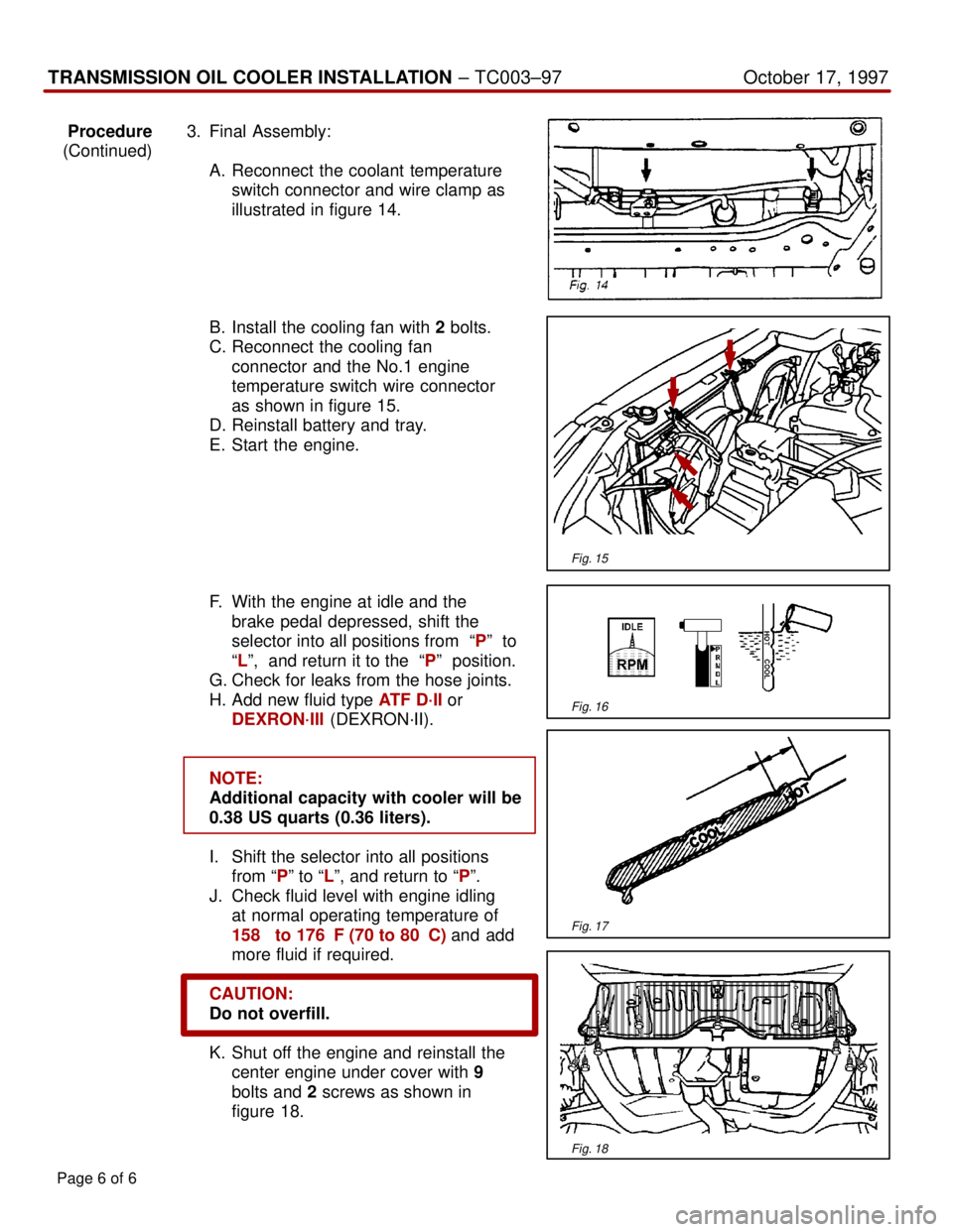
Procedure3. Final Assembly:
(Continued)
A. Reconnect the coolant temperature
switch connector and wire clamp as
illustrated in figure 14.
B. Install the cooling fan with 2 bolts.
C. Reconnect the cooling fan
connector and the No.1 engine
temperature switch wire connector
as shown in figure 15.
D. Reinstall battery and tray.
E. Start the engine.
F. With the engine at idle and the
brake pedal depressed, shift the
selector into all positions from ªPº to
ªLº, and return it to the ªPº position.
G. Check for leaks from the hose joints.
H. Add new fluid type ATF D´II or
DEXRON´III (DEXRON´II).
NOTE:
Additional capacity with cooler will be
0.38 US quarts (0.36 liters).
I. Shift the selector into all positions
from ªPº to ªLº, and return to ªPº.
J. Check fluid level with engine idling
at normal operating temperature of
158� to 176�F (70 to 80�C) and add
more fluid if required.
CAUTION:
Do not overfill.
K. Shut off the engine and reinstall the
center engine under cover with 9
bolts and 2 screws as shown in
figure 18.
Page 6 of 6
Fig. 15
Fig. 16
Fig. 17
Fig. 18
Page 3958 of 4592

O2S TEST RESULTS (MODE 05) ± SS002-03December 17, 2003
Page 2 of 43
1. Clear any stored Diagnostic Trouble Codes (DTCs) using the Toyota
Diagnostic Tester.
2. Start the engine.
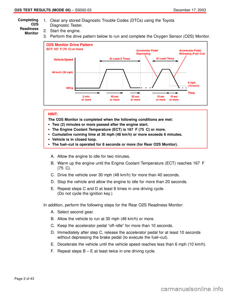
3. Perform the drive pattern below to run and complete the Oxygen Sensor (O2S) Monitor.
O2S Monitor Drive Pattern
ECT: 167�F (75�C) or more
Vehicle Speed
At Least 8 Times
48 km/h (30 mph)
IdlingAt Least Twice Accelerator Pedal
DepressingAccelerator Pedal
Releasing (Fuel±Cut)
6 mph
(10 km/h)
Time2 min.
or more40 sec
or more20 sec
or more10 sec
or more10 sec
or more
HINT:
The O2S Monitor is completed when the following conditions are met:
�Two (2) minutes or more passed after the engine start.
�The Engine Coolant Temperature (ECT) is 167�F (75�C) or more.
�Cumulative running time at 30 mph (48 km/h) or more exceeds 6 minutes.
�Vehicle is in closed loop.
�The fuel±cut is operated for 8 seconds or more (for Rear O2S Monitor).
A. Allow the engine to idle for two minutes.
B. Warm up the engine until the Engine Coolant Temperature (ECT) reaches 167�F
(75�C).
C. Drive the vehicle over 30 mph (48 km/h) for more than 40 seconds.
D. Stop the vehicle and allow the engine to idle for more than 20 seconds.
E. Repeat steps C and D at least 8 times in one driving cycle.
(Do not cycle the ignition key.)
In addition, perform the following steps for the Rear O2S Readiness Monitor:
A. Select second gear.
B. Allow the vehicle to run at 30 mph (48 km/h) or more.
C. Keep the accelerator pedal ªoff±idleº for more than 10 seconds.
D. Immediately after step C, release the accelerator pedal for at least 10 seconds
without depressing the brake pedal (to execute the fuel±cut).
E. Decelerate the vehicle until the vehicle speed reaches less than 6 mph (10 km/h).
F. Repeat steps B ± E at least twice in one driving cycle.
Completing
O2S
Readiness
Monitor
Page 4037 of 4592

G ELECTRICAL WIRING ROUTING
Position of Parts in Engine Compartment
A 1 A/C Condenser Fan Motor
A 2 A/C Magnetic Clutch and Lock Sensor
A 3 A/C Triple Pressure SW
(A/C Dual and Single Pressure SW)
A 4 ABS Actuator
A 5 ABS Actuator
A 6 ABS Speed Sensor Front LH
A 7 ABS Speed Sensor Front RH
A 8 Air Fuel Ratio Sensor
A 9 Airbag Sensor Front LH
A 10 Airbag Sensor Front RH
B 1 Brake Fluid Level Warning SW
C 1 Camshaft Position Sensor
C 2 Crankshaft Position Sensor
C 3 Cruise Control Actuator
D 1 Data Link Connector 1
E 1 Electronically Controlled Transmission Solenoid
E 2 Electronically Controlled Transmission Solenoid
E 3 Engine Coolant Temp. SensorF 1 Front Turn Signal Light and Parking Light LH
F 2 Front Turn Signal Light and Parking Light RH
F 3 Front Wiper Motor
F 4 Fuel Pressure Sensor (Delivery Pipe)
F 5 Fuel Pressure Sensor (Fuel Pipe)
F 6 Fuel Shutoff Valve (Delivery Pipe)
F 7 Fuel Shutoff Valve (Fuel Pressure Regulator)
F 8 Fuel Temp. Sensor (Delivery Pipe)
F 9 Fusible Link Block
F 10 Fusible Link Block
F 11 Fusible Link Block
F 12 Fusible Link Block
F 13 Fusible Link Block
F 14 Fusible Link Block
G 1 Generator
G 2 Generator
H 1 Headlight LH
H 2 Headlight RH
H 3 Horn (High)
H 4 Horn (Low)