Page 3356 of 4592
SF0DR±03
S05534
(a)
(c)
(b)
B01283
SF±34
± SFI (5S±FE)THROTTLE BODY
1467 Author�: Date�:
INSTALLATION
1. INSTALL THROTTLE BODY
(a) Connect the water bypass hose (from the water bypass
pipe) to the throttle body.
(b) Connect the water bypass hose (from the water outlet) to
the throttle body.
(c) California:
Connect the air hose (from the intake manifold) for air as-
sist system to the throttle body.
(d) Install a new gasket and the throttle body with the 3 bolts.
Torque: 19 N´m (195 kgf´cm, 14 ft´lbf)
(e) Connect the 2 vacuum hoses to the throttle body.
(f) Connect the throttle position sensor connector.
(g) Connect the IAC valve connector.
2. CONNECT ACCELERATOR CABLE TO THROTTLE
BODY
3. A/T:
CONNECT THROTTLE CABLE TO THROTTLE BODY
4. INSTALL AIR CLEANER CAP (See page EM±75)
5. FILL WITH ENGINE COOLANT
Page 3370 of 4592
SF0E5±03
B06361
ECT Sensor Connector
ECT Sensor
� Gasket
� Non±reusable part
SF±48
± SFI (5S±FE)ENGINE COOLANT TEMPERATURE (ECT) SENSOR
1481 Author�: Date�:
ENGINE COOLANT TEMPERATURE (ECT) SENSOR
COMPONENTS
Page 3371 of 4592
SF0E6±03
S01196S01699Z17274
Ohmmeter
Resistance kW
Temperature °C (°F) Acceptable 30
20
10
5
3
2
1
0.5
0.3
0.2
0.1
40 ±20 0 20 60 80 100
(212) (176) (140) (104) (68) (32) (±4)
± SFI (5S±FE)ENGINE COOLANT TEMPERATURE (ECT) SENSOR
SF±49
1482 Author�: Date�:
INSPECTION
1. DRAIN ENGINE COOLANT
2. REMOVE ECT SENSOR
3. INSPECT ECT SENSOR
Using an ohmmeter, measure the resistance between the ter-
minals.
Resistance: Refer to the graph
If the resistance is not as specified, replace the ECT sensor.
4. REINSTALL ECT SENSOR
5. REFILL WITH ENGINE COOLANT
Page 3427 of 4592
SF07V±03
S04506
S06123
(a)
(b)
(d) (e)
(c)
S04527
EGR Gas Temperature
Sensor Bracket
± SFI (1MZ±FE)THROTTLE BODY
SF±39
1538 Author�: Date�:
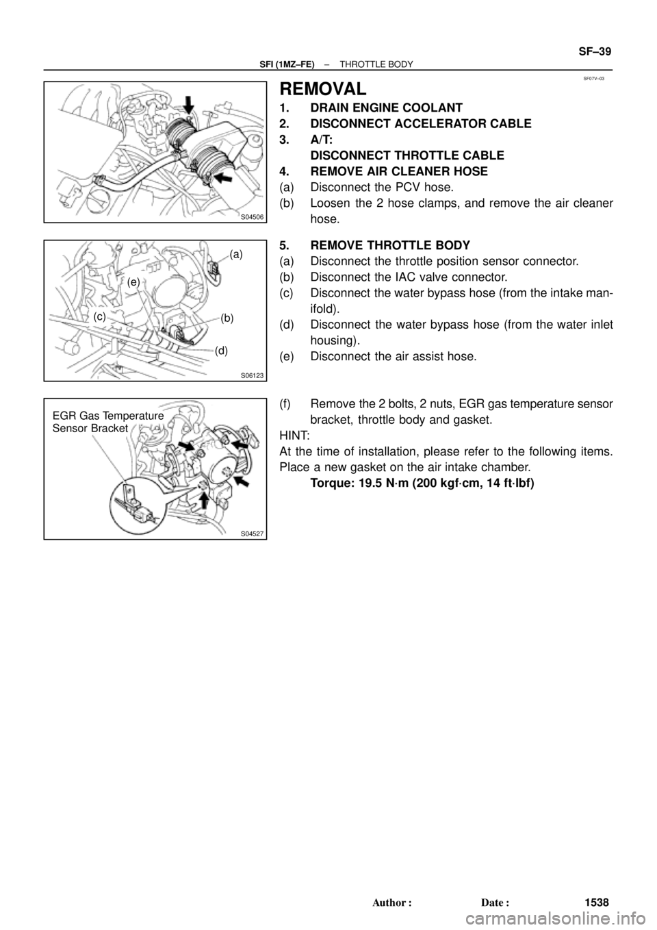
REMOVAL
1. DRAIN ENGINE COOLANT
2. DISCONNECT ACCELERATOR CABLE
3. A/T:
DISCONNECT THROTTLE CABLE
4. REMOVE AIR CLEANER HOSE
(a) Disconnect the PCV hose.
(b) Loosen the 2 hose clamps, and remove the air cleaner
hose.
5. REMOVE THROTTLE BODY
(a) Disconnect the throttle position sensor connector.
(b) Disconnect the IAC valve connector.
(c) Disconnect the water bypass hose (from the intake man-
ifold).
(d) Disconnect the water bypass hose (from the water inlet
housing).
(e) Disconnect the air assist hose.
(f) Remove the 2 bolts, 2 nuts, EGR gas temperature sensor
bracket, throttle body and gasket.
HINT:
At the time of installation, please refer to the following items.
Place a new gasket on the air intake chamber.
Torque: 19.5 N´m (200 kgf´cm, 14 ft´lbf)
Page 3451 of 4592
SF08I±03
S04759
ECT Switch19 mm
Deep Socket
Wrench
Gasket
S01196S01699Z17274
Ohmmeter
Resistance kW
Temperature °C (°F) Acceptable 30
20
10
5
3
2
1
0.5
0.3
0.2
0.1
40 ±20 0 20 60 80 100
(212) (176) (140) (104) (68) (32) (±4)
± SFI (1MZ±FE)ENGINE COOLANT TEMPERATURE (ECT) SENSOR
SF±63
1562 Author�: Date�:
ENGINE COOLANT
TEMPERATURE (ECT) SENSOR
INSPECTION
1. DRAIN ENGINE COOLANT
2. REMOVE ECT SENSOR
(a) Disconnect the ECT sensor connector.
(b) Using a 19 mm deep socket wrench, remove the ECT
sensor and gasket.
3. INSPECT ECT SENSOR
Using an ohmmeter, measure the resistance between the ter-
minals.
Resistance: Refer to the graph
If the resistance is not as specified, replace the ECT sensor.
4. REINSTALL ECT SENSOR
(a) Install a new gasket to the ECT sensor.
(b) Using a 19 mm deep socket, install the ECT sensor.
Torque: 20 N´m (200 kgf´cm, 14 ft´lbf)
(c) Connect the ECT sensor connector.
5. REFILL WITH ENGINE COOLANT
Page 3454 of 4592
SF08I±03
S04759
ECT Switch19 mm
Deep Socket
Wrench
Gasket
S01196S01699Z17274
Ohmmeter
Resistance kW
Temperature °C (°F) Acceptable 30
20
10
5
3
2
1
0.5
0.3
0.2
0.1
40 ±20 0 20 60 80 100
(212) (176) (140) (104) (68) (32) (±4)
± SFI (1MZ±FE)ENGINE COOLANT TEMPERATURE (ECT) SENSOR
SF±63
1562 Author�: Date�:
ENGINE COOLANT
TEMPERATURE (ECT) SENSOR
INSPECTION
1. DRAIN ENGINE COOLANT
2. REMOVE ECT SENSOR
(a) Disconnect the ECT sensor connector.
(b) Using a 19 mm deep socket wrench, remove the ECT
sensor and gasket.
3. INSPECT ECT SENSOR
Using an ohmmeter, measure the resistance between the ter-
minals.
Resistance: Refer to the graph
If the resistance is not as specified, replace the ECT sensor.
4. REINSTALL ECT SENSOR
(a) Install a new gasket to the ECT sensor.
(b) Using a 19 mm deep socket, install the ECT sensor.
Torque: 20 N´m (200 kgf´cm, 14 ft´lbf)
(c) Connect the ECT sensor connector.
5. REFILL WITH ENGINE COOLANT
Page 3457 of 4592

SF08K±03
B06390
VSV Connector for
EVAP
Ground Cable
PCV Hose
Air Intake Chamber
Assembly
ECT Sensor
Connector ECT Sender
Gauge ConnectorEGR Valve Position
Sensor Connector
IAC Valve
Connector
VSV Connector
for EGR
VSV Connector for ACIS
Engine Wire
Engine Coolant
Reservoir HoseAir Assist Hose
Water Bypass Hose No.2 EGR Pipe
Throttle Position
Sensor Connector
No.1 Engine
HangerBrake Booster
Vacuum Hose Air Intake Chamber Stay
Water OutletPS Pressure Tube
�Gasket
19.5 (200, 14)
39 (400, 19)12 (120, 19)
15 (150, 11)
�Gasket
43 (440, 32)
Ground Starp
DLC1
�Gasket
15 (150, 11)
Grand Strap
Connector
�Gasket
39 (400, 29)
V±Bank Cover
Accelerator Cable
Throttle Cable
Air Cleaner
Hose
Purge HoseEGR Gas Temperature
Sensor Connector
Vacuum
HoseWater Bypass Hose
Fuel Inlet Hose
Heater Hose
Intake Manifold Assembly
Injector Connector x 9
Knock Sensor
Connector
Upper Radiator
Hose
Engine
Wire
Band
High±Tension Cord
Set �Gasket
: Specified torque
�Non±reusable partN´m (kgf´cm, ft´lbf)
�Retainer
Knock Sensor
SF±66
± SFI (1MZ±FE)KNOCK SENSOR
1565 Author�: Date�:
KNOCK SENSOR
COMPONENTS
Page 3772 of 4592

READINESS MONITOR DRIVE PATTERNS ± EG003-02 RevisedMarch 29, 2002
Page 2 of 23
J1930 TERMJ1930 DEFINITIONTOYOTA/LEXUS DIAGNOSTIC TESTER PARAMETER
IATIntake Air TemperatureIntake Air
ECTEngine Coolant TemperatureCoolant Temp
TOOLS & MATERIALPART NUMBERQUANTITY
Toyota Diagnostic Tester Kit010012711
12 Megabyte Diagnostic Tester Program Card
with version 9.0a Software (or later)01002593-0051
NOTE:
A generic OBDII Scantool can be used in place of the Toyota Diagnostic Tester.
CAUTION:
Strict observance of posted speed limits, traffic laws and road conditions are
required when performing these drive patterns.
NOTE:
�These drive patterns represent the fastest method to satisfy all necessary
conditions which allow the specific Readiness Monitor to complete.
�In the event that the drive pattern must be interrupted (possibly due to traffic
conditions or other factors) the drive pattern can be resumed and, in most cases,
the Readiness Monitor will still set to ªcomplete.º
�To ensure rapid completion of Readiness Monitors, avoid sudden changes in
vehicle load and speed (driving up and down hills and/or sudden acceleration).
SAMPLE EMISSION CONTROL INFORMATION LABEL
EGR = Exhaust Gas Recirculation
A/F S = Air Fuel Sensor
O2S = Oxygen Sensor
0.19±0.29 mm [0.007±0.011 in.]
0.28±0.38 mm [0.011±0.015 in.]INTAKE
EXHAUSTVALVE CLEARANCE
(ENGINE AT COLD)
NO OTHER ADJUSTMENTS NEEDED.
ENGINE TUNE±UP SPECIFICATIONS FOR ALL ALTITUDES
7A650
2 2 V A G J J Y
2AZ±FE USA
SFI, EGR, A/F S, WU±TWC, TWC, HO2S
2.2 LITER TEST GROUP : 1TYXV02.2JJA
EVAP. FAMILY : 1TYXR0135AK1
TOYOTA MOTOR CORPORATION VEHICLE EMISSION CONTROL INFORMATION
Terms &
Definitions
Required
Tools &
Material
Underhood
Emission
Control
Information
Label


 Acceptable 30
20
10
5
3
2
1
0.5
0.3
0.2
0.1
40 ±20 0 20 60 80 100
(212) (176) (140) (104) (68) (32) (±4)
± SFI (5S±FE)ENGI")
 Acceptable 30
20
10
5
3
2
1
0.5
0.3
0.2
0.1
40 ±20 0 20 60 80 100
(212) (176")
 Acceptable 30
20
10
5
3
2
1
0.5
0.3
0.2
0.1
40 ±20 0 20 60 80 100
(212) (176")