Page 3056 of 4592
PP0C3±04
± PREPARATIONCOOLING (1MZ±FE)
PP±31
83 Author�: Date�:
COOLANT
ItemCapacityClassification
Engine coolant9.2 liters (9.7 US qts, 8.1 lmp. qts)ºToyota Long Life Coolantº or equivalent
Page 3149 of 4592
PP0L0±02
± PREPARATIONBODY ELECTRICAL
PP±13
EQUIPMENT
Voltmeter
Ammeter
Ohmmeter
Test lead
Bulb (3.4 W)Fuel sender gauge, Engine coolant temperature sender gauge
Torque wrench
Page 3242 of 4592

SS±15
178 Author�: Date�:
No.2 RH engine mounting stay x No.2 Generator bracket6465047
RH engine mounting stay x Water outlet3232023
RH engine mou")
± SERVICE SPECIFICATIONSENGINE MECHANICAL (1MZ±FE)
SS±15
178 Author�: Date�:
No.2 RH engine mounting stay x No.2 Generator bracket6465047
RH engine mounting stay x Water outlet3232023
RH engine mounting stay x Engine moving control rod3232023
RH engine mounting stay x No.2 RH engine mounting bracket3232023
Front engine mounting insulator x Front frame
TMC made
TMMK made Silver color bolt
Green color bolt
80
44
66820
450
67059
32
48
Engine mounting absorber x Front frame4849035
Engine mounting absorber x Transaxle4849035
Rear engine mounting insulator x Front frame6667048
LH engine mounting insulator x Transaxle6465047
PS pump x PS pump bracket4344031
A/C compressor x Housing bracket2525018
A/C compressor x No.1 oil pan2525018
Generator adjusting bar x Drive belt adjusting bar bracket1818513
Main bearing cap x Cylinder block 12 pointed head bolt 1st
2nd
6 pointed head bolt22
Turn 90°
27225
Turn 90°
27516
Turn 90°
20
Connecting rod cap x Connecting rod 1st
2nd24.5
Turn 90°250
Turn 90°18
Turn 90°
Rear oil seal retainer x Cylinder block88069 in.´lbf
EGR cooler x Cylinder block99078 in.´lbf
Engine coolant drain union x Cylinder block3940029
Water seal plate x Cylinder block1818013
Oil filter union x Cylinder block3031022
Water inlet housing x Cylinder block88069 in.´lbf
Knock sensor x Cylinder block3940029
No.2 idler pulley bracket x Cylinder block2829021
A/C compressor housing bracket x Cylinder block2525018
Generator bracket x Cylinder block4344032
Drive plate x Crankshaft8385061
Flywheel x Crankshaft8385061
Front exhaust pipe support bracket x No.1 oil pan2121015
Front exhaust pipe x Exhaust manifold6263046
Front exhaust pipe x Center exhaust pipe5657041
Center exhaust pipe x Tailpipe5657041
Front exhaust pipe bracket x Sub frame3333024
Front exhaust pipe support bracket x Front exhaust pipe stay3333024
Heated oxygen sensor x Center exhaust pipe4445033
Page 3253 of 4592

SS±15
178 Author�: Date�:
No.2 RH engine mounting stay x No.2 Generator bracket6465047
RH engine mounting stay x Water outlet3232023
RH engine mou")
± SERVICE SPECIFICATIONSENGINE MECHANICAL (1MZ±FE)
SS±15
178 Author�: Date�:
No.2 RH engine mounting stay x No.2 Generator bracket6465047
RH engine mounting stay x Water outlet3232023
RH engine mounting stay x Engine moving control rod3232023
RH engine mounting stay x No.2 RH engine mounting bracket3232023
Front engine mounting insulator x Front frame
TMC made
TMMK made Silver color bolt
Green color bolt
80
44
66820
450
67059
32
48
Engine mounting absorber x Front frame4849035
Engine mounting absorber x Transaxle4849035
Rear engine mounting insulator x Front frame6667048
LH engine mounting insulator x Transaxle6465047
PS pump x PS pump bracket4344031
A/C compressor x Housing bracket2525018
A/C compressor x No.1 oil pan2525018
Generator adjusting bar x Drive belt adjusting bar bracket1818513
Main bearing cap x Cylinder block 12 pointed head bolt 1st
2nd
6 pointed head bolt22
Turn 90°
27225
Turn 90°
27516
Turn 90°
20
Connecting rod cap x Connecting rod 1st
2nd24.5
Turn 90°250
Turn 90°18
Turn 90°
Rear oil seal retainer x Cylinder block88069 in.´lbf
EGR cooler x Cylinder block99078 in.´lbf
Engine coolant drain union x Cylinder block3940029
Water seal plate x Cylinder block1818013
Oil filter union x Cylinder block3031022
Water inlet housing x Cylinder block88069 in.´lbf
Knock sensor x Cylinder block3940029
No.2 idler pulley bracket x Cylinder block2829021
A/C compressor housing bracket x Cylinder block2525018
Generator bracket x Cylinder block4344032
Drive plate x Crankshaft8385061
Flywheel x Crankshaft8385061
Front exhaust pipe support bracket x No.1 oil pan2121015
Front exhaust pipe x Exhaust manifold6263046
Front exhaust pipe x Center exhaust pipe5657041
Center exhaust pipe x Tailpipe5657041
Front exhaust pipe bracket x Sub frame3333024
Front exhaust pipe support bracket x Front exhaust pipe stay3333024
Heated oxygen sensor x Center exhaust pipe4445033
Page 3305 of 4592

USA:
Standard indicat")
SS0B0±05
± SERVICE SPECIFICATIONSBODY ELECTRICAL
SS±67
230 Author�: Date�:
BODY ELECTRICAL
SERVICE DATA
TURN SIGNAL FLASHER
Flashes/ Minute60 ± 120
SPEEDOMETER (ON±VEHICLE)
USA:
Standard indication (mph)Allowable range (mph)
2018 ± 24
4038 ± 44
6056 ± 66
8078 ± 88
10098 ± 110
120118 ± 132
CANADA:
Standard indication (km/h)Allowable range (km/h)
2017 ± 24
4038 ± 46
6057.5 ± 67
8077 ± 88
10096 ± 109
120115 ± 130
140134 ± 151.5
160153 ± 173
TACHOMETER (ON±VEHICLE)/ DC 13.5 V 25 °C at (77 °F)
Standard indicationAllowable range
700630 ± 770
1,000900 ± 1,100
2,0001,850 ± 2,150
3,0002,800 ± 3,200
4,0003,800 ± 4,200
5,0004,800 ± 5,200
6,0005,750 ± 6,250
7,0006,700 ± 7,300
FUEL RECEIVER GAUGE
A ± BApprox. 126.2 W
A ± CApprox. 280.5 W
B ± CApprox. 154.3 W
FUEL SENDER GAUGE
Float position mm (in.)Resistance (W)
F: Approx. ±91.1 (±3.587)Approx. 3.0
1/2: Approx. ±34.2 (±1.346)Approx. 31.7
E: Approx. 30.8 (1.213)Approx. 110.0
ENGINE COOLANT TEMPERATURE RECEIVER GAUGE (Resistance)
A ± BApprox. 175.7 W
A ± CApprox. 54.0 W
Page 3306 of 4592
SS±68
± SERVICE SPECIFICATIONSBODY ELECTRICAL
231 Author�: Date�:
B ± CApprox. 229.7 W
ENGINE COOLANT TEMPERATURE SENDER GAUGE (Resistance)
Temperature °C (°F)Resistance (W)
50 (122.0)274
120 (248.0)26.4
Page 3321 of 4592
SS0B0±06
± SERVICE SPECIFICATIONSBODY ELECTRICAL
SS±11
69 Author�: Date�:
BODY ELECTRICAL
SERVICE DATA
FUEL RECEIVER GAUGE
A ± BApprox. 270.1 W
A ± CApprox. 141.3 W
B ± CApprox. 128.8 W
ENGINE COOLANT TEMPERATURE RECEIVER GAUGE (Resistance)
A ± BApprox. 175.7 W
A ± CApprox. 54.0 W
B ± CApprox. 229.7 W
ENGINE COOLANT TEMPERATURE SENDER GAUGE (Resistance)
Temperature °C (°F)Resistance (W)
50 (122.0)160 ± 240
120 (248.0)17.1 ± 21.2
Page 3354 of 4592
SF0DP±03
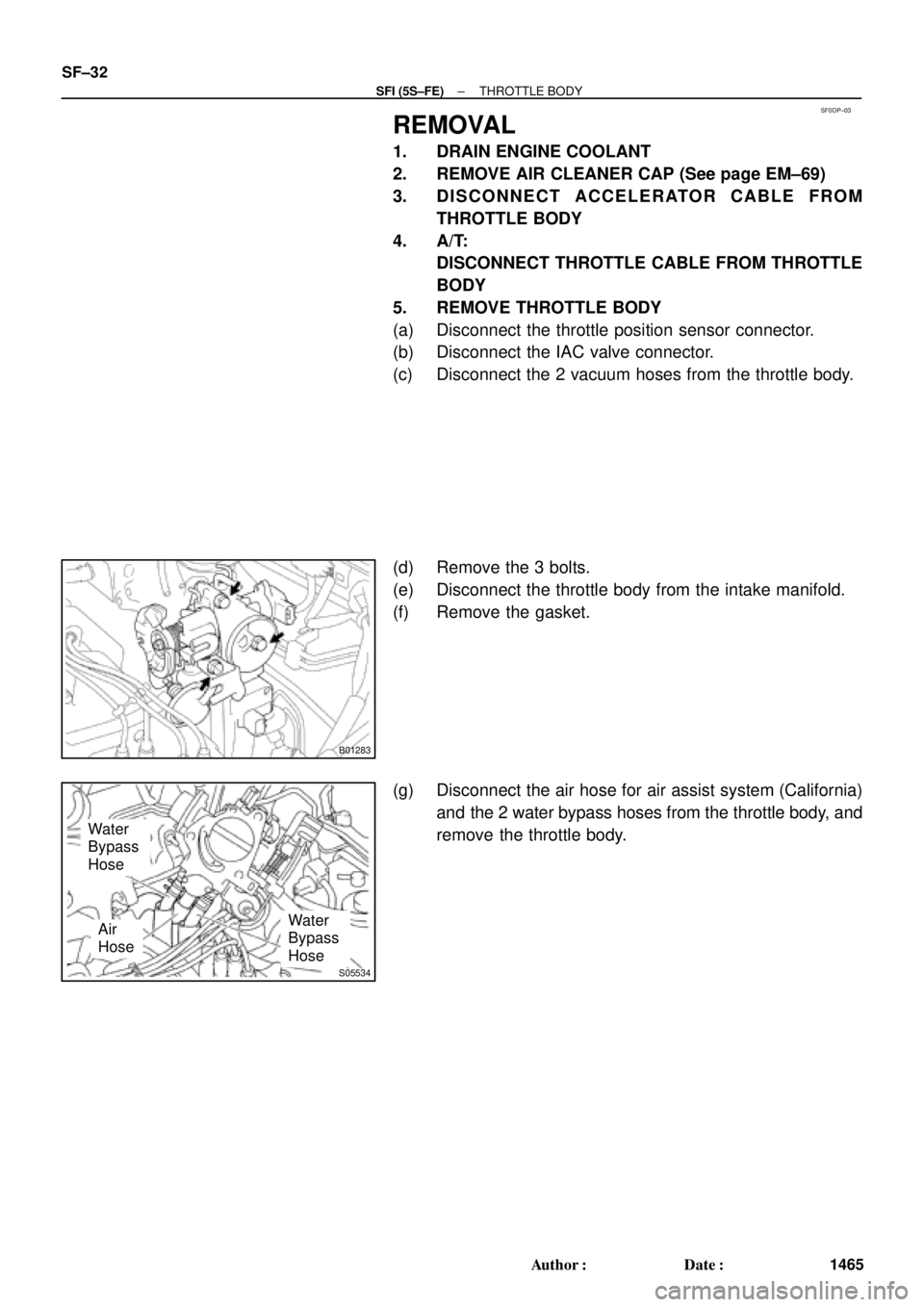
B01283
S05534
Water
Bypass
Hose
Water
Bypass
HoseAir
Hose SF±32
± SFI (5S±FE)THROTTLE BODY
1465 Author�: Date�:
REMOVAL
1. DRAIN ENGINE COOLANT
2. REMOVE AIR CLEANER CAP (See page EM±69)
3. DISCONNECT ACCELERATOR CABLE FROM
THROTTLE BODY
4. A/T:
DISCONNECT THROTTLE CABLE FROM THROTTLE
BODY
5. REMOVE THROTTLE BODY
(a) Disconnect the throttle position sensor connector.
(b) Disconnect the IAC valve connector.
(c) Disconnect the 2 vacuum hoses from the throttle body.
(d) Remove the 3 bolts.
(e) Disconnect the throttle body from the intake manifold.
(f) Remove the gasket.
(g) Disconnect the air hose for air assist system (California)
and the 2 water bypass hoses from the throttle body, and
remove the throttle body.

Fuel sender gauge, Engine coolant temperature sender gauge
Torque wrench")