Page 3155 of 4592

H02309
H02266
H08235
H03284
± SUPPLEMENTAL RESTRAINT SYSTEMSRS AIRBAG
RS±3
2148 Author�: Date�:
6. SRS WARNING LIGHT
The SRS warning light is located on the combination meter. It
goes on to alert the driver of trouble in the system when a mal-
function is detected in the airbag sensor assembly self±diagno-
sis. In normal operation conditions when the ignition switch is
turned to the ACC or ON position, the light goes on for about 6
seconds and then goes off.
7. AIRBAG SENSOR ASSEMBLY
The airbag sensor assembly is mounted on the floor inside the
lower center finish panel. The airbag sensor assembly consists
of an airbag sensor, safing sensor, diagnosis circuit, ignition
control and drive circuit, etc. It receives signals from the airbag
sensor and judges whether the SRS must be activated or not.
8. FRONT AIRBAG SENSOR
A front airbag sensor is mounted inside each of the side mem-
bers. The sensor unit is a mechanical type. When the sensor
detects deceleration force above a predetermined limit, contact
is made in the sensor, sending a signal to the airbag sensor as-
sembly. The sensor cannot be disassembled.
9. SIDE AIRBAG SENSOR ASSEMBLY
The side airbag sensor assembly is mounted in the LH and RH
center pillars. The side airbag sensor assembly consists of a lat-
eral deceleration sensor, safing sensor and diagnosis circuit,
etc. It receives signals to the airbag sensor assembly to judge
from the side airbag sensors whether the SRS side airbag must
be activated or not.
Page 3159 of 4592
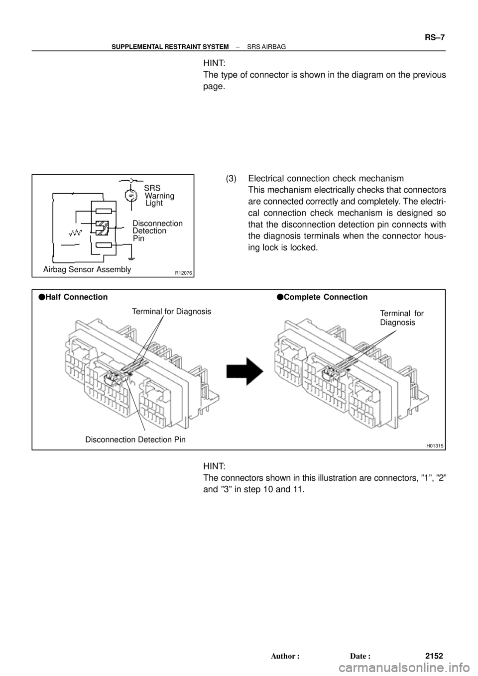
R12076Airbag Sensor AssemblyDisconnection
Detection
PinSRS
Warning
Light
H01315
Terminal for Diagnosis
Disconnection Detection Pin �Half Connection�Complete Connection
Terminal for
Diagnosis
± SUPPLEMENTAL RESTRAINT SYSTEMSRS AIRBAG
RS±7
2152 Author�: Date�:
HINT:
The type of connector is shown in the diagram on the previous
page.
(3) Electrical connection check mechanism
This mechanism electrically checks that connectors
are connected correctly and completely. The electri-
cal connection check mechanism is designed so
that the disconnection detection pin connects with
the diagnosis terminals when the connector hous-
ing lock is locked.
HINT:
The connectors shown in this illustration are connectors, º1º, º2º
and º3º in step 10 and 11.
Page 3225 of 4592
RS01V±11
H08282
Spiral CableCombination Meter
(Warning Light)Front Passenger Airbag Assembly
Side Airbag Assembly (RH)
Side Airbag Sensor
Assembly (RH)
Seat Belt Pretensioner (RH) Steering Wheel Pad
(with Airbag)
Side Airbag Sensor
Assembly (LH)
Seat Belt Pretensioner (LH)
Side Airbag Assembly (LH)
Airbag Sensor Assembly
Front Airbag Sensor (RH)
Front Airbag
Sensor (LH)
± SUPPLEMENTAL RESTRAINT SYSTEMWIRE HARNESS AND CONNECTOR
RS±73
2218 Author�: Date�:
WIRE HARNESS AND CONNECTOR
LOCATION
Page 3516 of 4592
F01476
Key Unlock Warning Switch
Column Upper Bracket Ignition Switch
Energy Absorbing PlateTransponder Key Coil Key Cylinder Lamp Assembly
Key
Interlock
Solenoid Key Cylinder
Transponder Key
Amplifier
Energy Absorbing Plate
Guide� Energy Absorbing Clip
Energy Absorbing Plate
Energy Absorbing Plate
Guide
� Energy Absorbing Clip Column TubeTilt Lever
Return Spring
� Tapered±Head Bolt Column Upper Tube Turn Signal Bracket
Lower Column Tube AttachmentColumn Tube Support
7 (70, 61 in.´lbf)
19 (195, 14)
N´m (kgf´cm, ft´lbf): Specified torque
� Non±reusable partw/ ENGINE IMMOBILISER SYSTEM:
A/T: SR±10
± STEERINGTILT STEERING COLUMN
2105 Author�: Date�:
Page 3520 of 4592

SR06K±01
W03335
Ignition Key
W03336
SR±14
± STEERINGTILT STEERING COLUMN
2109 Author�: Date�:
INSPECTION
1. INSPECT STEERING LOCK OPERATION
Check that the steering lock mechanism operates properly.
2. IF NECESSARY, REPLACE KEY CYLINDER
(a) Place the ignition key at the ACC position.
(b) Push down the stop pin with a screwdriver, and pull out
the cylinder.
(c) Install a new cylinder.
HINT:
Make sure the key is at the ACC position.
3. INSPECT IGNITION SWITCH
(See page BE±14)
4. IF NECESSARY, REPLACE IGNITION SWITCH
(a) Remove the 2 screws.
(b) Install a new switch with the 2 screws.
5. INSPECT KEY UNLOCK WARNING SWITCH
(See page BE±14)
6. IF NECESSARY, REPLACE KEY UNLOCK WARNING
SWITCH
(a) Slide out the switch.
(b) Install a new switch.
7. A/T:
INSPECT KEY INTERLOCK SOLENOID
(A140E: See page AX±13)
(A541E: See page AX±17)
8. A/T:
IF NECESSARY, REPLACE KEY INTERLOCK SOLE-
NOID
(a) Remove the 2 screws.
(b) Install a new solenoid with the 2 screws.
9. w/ ENGINE IMMOBILISER SYSTEM:
INSPECT TRANSPONDER KEY COIL
(See page BE±128)
10. w/ ENGINE IMMOBILISER SYSTEM:
IF NECESSARY, REPLACE TRANSPONDER KEY
COIL
11. w/ ENGINE IMMOBILISER SYSTEM:
IF NECESSARY, REPLACE TRANSPONDER KEY AM-
PLIFIER
(a) Remove the 2 screws.
(b) Install a new key amplifier with the 2 screws.
Page 3672 of 4592

Toyota Supports ASE CertificationPage 1 of 2
AX006±99Title:
RS3000 TVIP PROGRAMMING CHANGES
FOR GBS
Models:
All Models
Technical Service
BULLETIN
April 23, 1999
Starting with 1999 MY, the programming in the RS3000 ECU for the Glass Breakage
Sensor (GBS) to trigger the alarm has been changed to improve the Toyota Vehicle
Intrusion Protection (TVIP) system's theft warning feature when glass breakage or impact
to the glass is detected.
Previous operation of GBS (for 1998 MY and prior):
�Upon (first) detection of breakage of the vehicle's glass, the GBS will sound the
security system for 5 seconds (3 horn honks).
�If there is a second detection of glass breakage, within 5 seconds of the first
detection, the security system will sound for the full duration of 59 seconds.
Improved operation of GBS (from 1999 MY):
�Upon (first) detection of breakage of the vehicle's glass, the GBS will sound the
security system for 20 seconds.
�If there is a second detection of glass breakage, the security system will sound for the
full duration of 59 seconds, regardless of time between the first and second
detections.
�After the first detection, any subsequent detection will trigger the alarm for the full
duration of 59 seconds as long as the security system is armed. The GBS trigger
cycle will reset once the security system is disarmed and then rearmed.
This improvement is intended to enhance the previous trigger cycle of the security
system and ward off an intruder.
The color of the previous (1998 MY and prior) RS3000 ECU was black. The new
RS3000 ECU color is gray.
�All Models
PREVIOUS PART NUMBERCURRENT PART NUMBERPART NAME
08585±00921SAMERS3000 Base Kit
OP CODEDESCRIPTIONTIMEOPNT1T2
N/ANot applicable to warranty ±±±±
ACCESSORIES
Introduction
Affected
Vehicles
Parts
Information
Warranty
Information
Page 3933 of 4592

Toyota Supports ASE CertificationPage 1 of 1
ST002±98Title:
STEERING GEAR REMOVAL/
REPLACEMENT
Models:
All Models equipped with SRS Airbag
Technical Service
BULLETIN
May 22, 1998
The following information is provided to supplement the Repair Manual procedure
for
removing/installing the steering gearbox or rack and pinion on vehicles equipped with a
driver 's side Supplemental Restraint System (SRS) Airbag.
CAUTION:
When the intermediate shaft is disconnected and the steering wheel is turned freely,
the SRS spiral cable may be broken.
Therefore, as a precaution, make sure to pass
the driver's seat belt through the steering wheel to prevent it from turning freely, as
shown below.
After working on SRS/Steering components, always check the operation of the SRS
Warning Light. Refer to the appropriate repair manual if any diagnostic trouble codes
are recorded.
Tercel, Paseo, Corolla, MR2, Celica, Camry, Avalon, Supra, Previa, Sienna, RAV4,
4Runner, Tacoma, T±100 & Land Cruiser equipped with a driver's side SRS Airbag.
1. Position the front wheels facing
straight ahead.
2. Using the driver's seat belt, set the
steering wheel so that it does not turn
(see Fig. 1).
3. Paint match marks on the
intermediate shaft and control valve
shaft (see Fig. 2).
4. Remove the intermediate shaft
retaining bolt and disconnect the
intermediate shaft (see Fig. 2).
OP CODEDESCRIPTIONTIMEOPNT1T2
N/ANot Applicable to Warranty ±±±±
STEERING
Introduction
Affected
Vehicles
Fig. 1
Repair
Procedure
Match Marks
Fig.2
Warranty
Information
Page 3941 of 4592

Toyota Supports ASE CertificationPage 1 of 1
SU002±00Title:
REAR ABS SPEED SENSOR REMOVAL
Models:
'97 ± '00 Camry & Avalon, '99 ± '00 Solara
Technical Service
BULLETIN
May 5, 2000
This bulletin provides service information regarding the removal of the ABS speed sensor
prior to removal of the rear axle and rear suspension.
REMINDER:
Failure to remove the ABS speed sensor prior to removal of the rear axle or
suspension may cause the ABS warning light to illuminate or damage the ABS speed
sensor wire harness.
�1997 ± 2000 model year Camry and Avalon
�1999 ± 2000 model year Solara
POTENTIAL AREA FOR DAMAGE
5.4 N�m (55 kgf�cm, 48 in�lbf)
7.8 N�m (80 kfg�cm, 69 in�lbf)
REAR ABS SPEED SENSOR
NOTE:
Prior to removal/replacement of the rear axle, rear coil spring and rear shock absorber,
be sure to remove the rear ABS speed sensor from the rear axle by removing the 3
bolts shown above. Check the speed sensor signal after installation.
OP CODEDESCRIPTIONTIMEOPNT1T2
N/ANot Applicable ±±±±
SUSPENSION
Introduction
Applicable
Vehicles
Repair
Procedure
Warranty
Information
Front Passenger Airbag Assembly
Side Airbag Assembly (RH)
Side Airbag Sensor
Assembly (RH)
Seat Belt Pretensioner (RH) Steering Wheel Pad")
