Page 2376 of 4592

AT0716AB0056H08231
Normal Code
ON
OFF0.25
0.25
Code 11 and 31
ON
OFF
0.5 2.54.0
1.5 0.5
DTC 11
DTC 31Repeat
S05331
TOYOTA Hand±Held Tester
DLC3 DI±224
± DIAGNOSTICSSUPPLEMENTAL RESTRAINT SYSTEM
(c) Read the DTC.
Read the 2±digit DTC as indicated by the number of times
the SRS warning light blinks. As an example, the blinking
patterns, normal, 11 and 31 are shown in the illustration.
�Normal code indication
The light will blink 2 times per second.
�Malfunction code indication
The first blinking output indicates the first digit
of a 2±digit DTC. After a 1.5±second pause,
the second blinking output will indicate the
second digit.
If there are 2 or more codes, there will be a 2.5±second pause
between each code. After all the codes have been output, there
will be a 4.0±second pause and they will all be repeated.
HINT:
�In the event of a number of trouble codes, indication will
start from the smallest numbered code.
�If a DTC is not output or a DTC is output without terminal
connection, proceed to the Tc terminal circuit inspection
on page DI±313.
3. DTC CHECK (Using TOYOTA hand±held tester)
(a) Hook up the TOYOTA hand±held tester to the DLC3.
(b) Read the DTCs by following the prompts on the tester
screen.
HINT:
Please refer to the TOYOTA hand±held tester operator's manu-
al for further details.
4. DTC CLEARANCE (Not using service wire)
When the ignition switch is turned off, the diagnostic trouble
code is cleared.
HINT:
DTC might not be cleared by turning the ignition switch OFF.
In this case, proceed to the next step.
5. DTC CLEARANCE (Using service wire)
(a) Connect the 2 service wires to terminals Tc and AB of
DLC1.
(b) Turn the ignition switch to ACC or ON and wait for approx.
6 seconds.
Page 2377 of 4592

H01461
H10313
H10314
ABTerminal
Tc
ABOFF
Body
Ground
OFF
ON
OFF
Several
Seconds50 m sec.
50 m sec.
1 seconds
(± 0.5 sec.)
Tc
Body
Ground
1 seconds
(± 0.5 sec.)
1
23
45
S05331
TOYOTA Hand±Held Tester
DLC3
± DIAGNOSTICSSUPPLEMENTAL RESTRAINT SYSTEM
DI±225
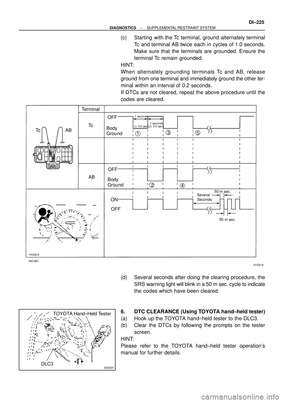
(c) Starting with the Tc terminal, ground alternately terminal
Tc and terminal AB twice each in cycles of 1.0 seconds.
Make sure that the terminals are grounded. Ensure the
terminal Tc remain grounded.
HINT:
When alternately grounding terminals Tc and AB, release
ground from one terminal and immediately ground the other ter-
minal within an interval of 0.2 seconds.
If DTCs are not cleared, repeat the above procedure until the
codes are cleared.
(d) Several seconds after doing the clearing procedure, the
SRS warning light will blink in a 50 m sec. cycle to indicate
the codes which have been cleared.
6. DTC CLEARANCE (Using TOYOTA hand±held tester)
(a) Hook up the TOYOTA hand±held tester to the DLC3.
(b) Clear the DTCs by following the prompts on the tester
screen.
HINT:
Please refer to the TOYOTA hand±held tester operation's
manual for further details.
Page 2381 of 4592

DI1AZ±09
± DIAGNOSTICSSUPPLEMENTAL RESTRAINT SYSTEM
DI±229
DIAGNOSTIC TROUBLE CODE CHART
If a malfunction code is displayed during the DTC check, check the circuit listed for that code in the table
below (Proceed to the page given for that circuit.).
DTC No.
(See Page)Detection ItemTrouble AreaSRS
Warning Light
B0100/13
(DI±234)
�Short in D squib circuit�Steering wheel pad (squib)
�Spiral cable
�Airbag sensor assembly
�Wire harness
ON
B0101/14
(DI±239)
�Open in D squib circuit�Steering wheel pad (squib)
�Spiral cable
�Airbag sensor assembly
�Wire harness
ON
B0102/11
(DI±243)
�Short in D squib circuit (to Ground)�Steering wheel pad (squib)
�Spiral cable
�Airbag sensor assembly
�Wire harness
ON
B0103/12
(DI±247)
�Short in D squib circuit (to B+)�Steering wheel pad (squib)
�Spiral cable
�Airbag sensor assembly
�Wire harness
ON
B0105/53
(DI±251)�Short in P squib circuit�Front passenger airbag assembly (squib)
�Airbag sensor assembly
�Wire harness
ON
B0106/54
(DI±255)�Open in P squib circuit�Front passenger airbag assembly (squib)
�Airbag sensor assembly
�Wire harness
ON
B0107/51
(DI±258)�Short in P squib circuit (to Ground)�Front passenger airbag assembly (squib)
�Airbag sensor assembly
�Wire harness
ON
B0108/52
(DI±261)�Short in P squib circuit (to B+)�Front passenger airbag assembly (squib)
�Airbag sensor assembly
�Wire harness
ON
B0130/63
(DI±264)�Short in P/T squib (RH) circuit�Seat belt pretensioner RH (squib)
�Airbag sensor assembly
�Wire harness
Blink
B0131/64
(DI±268)�Open in P/T squib (RH) circuit�Seat belt pretensioner RH (squib)
�Airbag sensor assembly
�Wire harness
Blink
B0132/61
(DI±271)�Short in P/T squib (RH) circuit
(to Ground)�Seat belt pretensioner RH (squib)
�Airbag sensor assembly
�Wire harness
Blink
B0133/62
(DI±274)�Short in P/T squib (RH) circuit
(to B+)�Seat belt pretensioner RH (squib)
�Airbag sensor assembly
�Wire harness
Blink
B0135/73
(DI±277)�Short in P/T squib (LH) circuit�Seat belt pretensioner LH (squib)
�Airbag sensor assembly
�Wire harness
Blink
B0136/74
(DI±281)�Open in P/T squib (LH) circuit�Seat belt pretensioner LH (squib)
�Airbag sensor assembly
�Wire harness
Blink
Page 2382 of 4592

DI±230
± DIAGNOSTICSSUPPLEMENTAL RESTRAINT SYSTEM
DTC No.
(See Page)
Detection ItemTrouble AreaSRS
Warning Light
B0137/71
(DI±284)�Short in P/T squib (LH) circuit
(to Ground)�Seat belt pretensioner LH (squib)
�Airbag sensor assembly
�Wire harness
Blink
B0138/72
(DI±287)�Short in P/T squib (LH) circuit
(to B+)�Seat belt pretensioner LH (squib)
�Airbag sensor assembly
�Wire harness
Blink
B1100/31
(DI±290)�Airbag sensor assembly malfunction�Airbag sensor assemblyON
B1156/B1157/
15
(DI±292)�Front airbag sensor (RH) malfunction�Front airbag sensor (RH)
�Wire harness
�Engine room main wire harness
�Airbag sensor assembly
ON
B1158/B1159/
16
(DI±300)�Front airbag sensor (LH) malfunction�Front airbag sensor (LH)
�Wire harness
�Airbag sensor assembly
ON
Nl�System normal±OFFNormal
(DI±305)�Voltage source drop�Battery
�Airbag sensor assemblyON
HINT:
�When the SRS warning light remains lit up and the DTC is the normal code, this means a voltage source
drops.
This malfunction is not stored in memory by the airbag sensor assembly and if the power source volt-
age returns to normal, the SRS warning light will automatically go out.
�When 2 or more codes are indicated, the codes will be displayed in numeral order starting from the
lowest numbered code.
�If a code not listed on the chart is displayed, the airbag sensor assembly is faulty.
Page 2383 of 4592
DI1B0±10
H10307
Combination Meter
(Warning Light)Steering Wheel Pad
(with Airbag)
Airbag Sensor AssemblyFront Passenger
Airbag Assembly
Seat Belt
Pretensioner (LH)Seat Belt
Pretensioner (RH) Front Airbag
Sensor (LH)Front Airbag Sensor (RH)
Spiral Cable
± DIAGNOSTICSSUPPLEMENTAL RESTRAINT SYSTEM
DI±231
PARTS LOCATION
Page 2384 of 4592
DI1B1±15
H01357
C5
C4C6
287 8 9 10 16 17
18A B12 3 4 5 6
11 12 15 14 13
AABB
19 20 21 22 23 24 25 26 27 1 2 3 4 5 6
7 8 9 10 11 121 2 3 4 5 6
7 8 9 10 11 12 DI±232
± DIAGNOSTICSSUPPLEMENTAL RESTRAINT SYSTEM
TERMINALS OF ECU
No.SymbolTerminal Name
A±Electrical Connector Check Mechanism
B±Electrical Connector Check Mechanism
C5 ± 3LASRS Warning Light
C5 ± 4GSWEFI ECU
C5 ± 5IG2Power Source (IGN Fuse)
C5 ± 6ACCPower Source (CIG Fuse)
C5 ± 9SR+Front Airbag Sensor (RH)
C5 ± 10P+Squib (Passenger)
C5 ± 11P±Squib (Passenger)
C5 ± 12SILDiagnosis
C5 ± 13D±Squib (Driver)
C5 ± 14D+Squib (Driver)
C5 ± 15SL+Front Airbag Sensor (LH)
C5 ± 19TcDiagnosis
C5 ± 20SR±Front Airbag Sensor (RH)
C5 ± 26SL±Front Airbag Sensor (LH)
C5 ± 27E1Ground
C5 ± 28E2Ground
C4 ± 1PL±Squib (Seat Belt Pretensioner, LH)
C4 ± 2PL+Squib (Seat Belt Pretensioner, LH)
C6 ± 5PR+Squib (Seat Belt Pretensioner, RH)
C6 ± 6PR±Squib (Seat Belt Pretensioner, RH)
Page 2385 of 4592
DI164±25
± DIAGNOSTICSSUPPLEMENTAL RESTRAINT SYSTEM
DI±233
PROBLEM SYMPTOMS TABLE
Proceed with troubleshooting of each circuit in the table below.
SymptomSuspect AreaSee page
�With the ignition switch in ACC or ON position, the SRS warning
light sometimes lights up after approx. 6 seconds have elapsed.�SRS warning light circuit
(Al li ht h i iti it h i i LOCK iDI 308�SRS warning light is always lit up even when ignition switch is in
the LOCK position.(Always lights up when ignition switch is in LOCK posi-
tion.)DI±308
�With the ignition switch in ACC or ON position, the SRS warning
light does not light up.�SRS warning light circuit
(Does not light up when ignition switch is turned to ACC or
ON.)
DI±308
�DTC is not displayed.
�SRS warning light is always lit up at the time of DTC check pro-
cedure.�Tc terminal circuitDI±313
�DTC is displayed without Tc and E1 terminal connection.
Page 2457 of 4592

H02288
15A CIG
L±R 2Airbag Sensor
Assembly 2
3 4
6 7
6
3B±R
65A IGN
C5 1K
IF 1K
1N1N
C5 Instrument Panel J/B
30A AM2
W±R W±R1
4 40A AM1
2L
1K2A
1B
1K1B
55 W2
1
2 Instrument Panel J/B
AF14 F9F11 FL MAIN
B±G
100A
ALT
Instrument Panel J/B Junction
Connector
W±B7
1J 1NW±BC5
1 Battery
1 1
2
5
B±O
GR
ACCIG2 Fusible Link Block
27
E1 Ignition Switch1 B±RB
± DIAGNOSTICSSUPPLEMENTAL RESTRAINT SYSTEM
DI±305
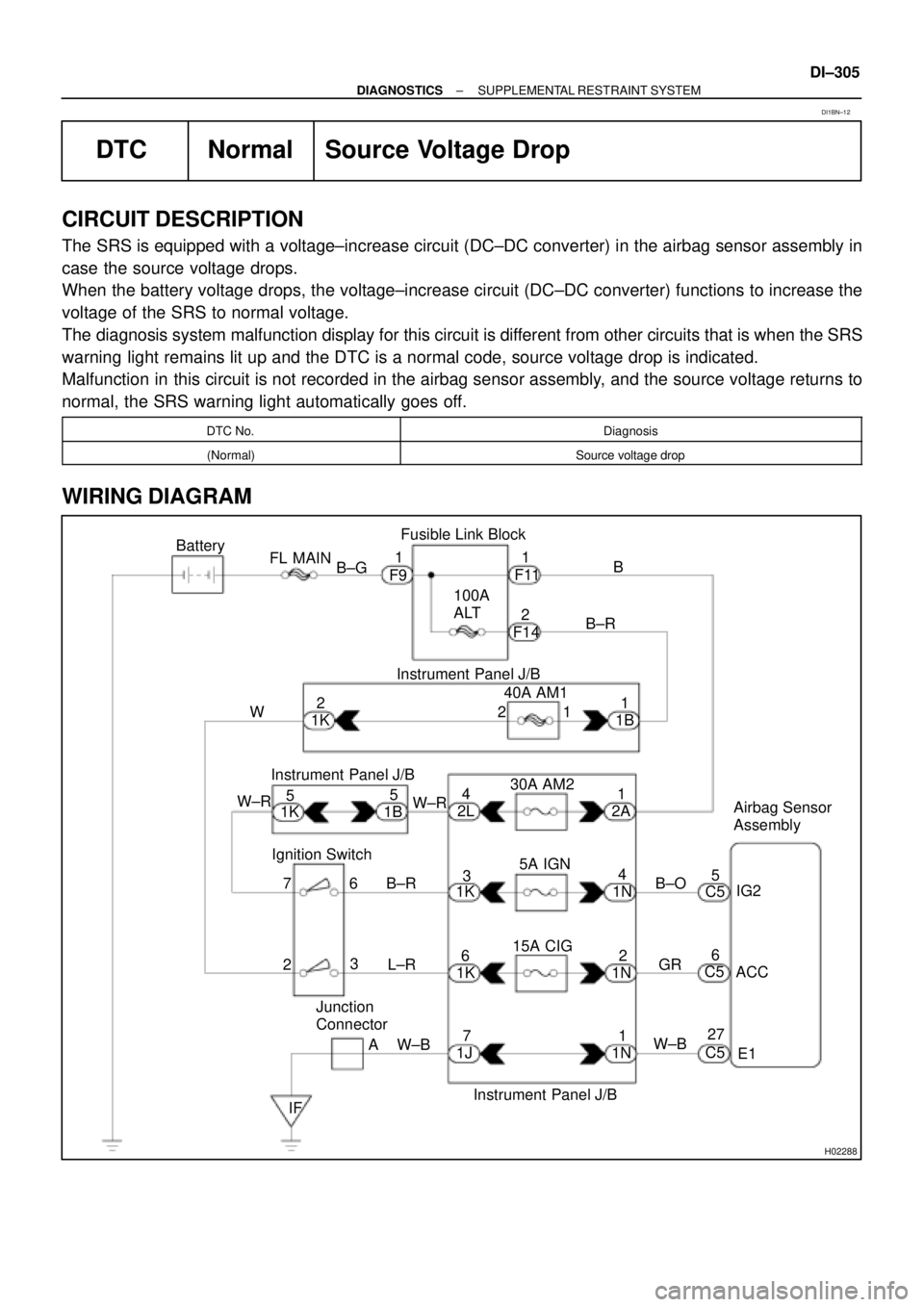
DTC Normal Source Voltage Drop
CIRCUIT DESCRIPTION
The SRS is equipped with a voltage±increase circuit (DC±DC converter) in the airbag sensor assembly in
case the source voltage drops.
When the battery voltage drops, the voltage±increase circuit (DC±DC converter) functions to increase the
voltage of the SRS to normal voltage.
The diagnosis system malfunction display for this circuit is different from other circuits that is when the SRS
warning light remains lit up and the DTC is a normal code, source voltage drop is indicated.
Malfunction in this circuit is not recorded in the airbag sensor assembly, and the source voltage returns to
normal, the SRS warning light automatically goes off.
DTC No.Diagnosis
(Normal)Source voltage drop
WIRING DIAGRAM
DI1BN±12