Page 610 of 4592
BE0A8±03
Z19045
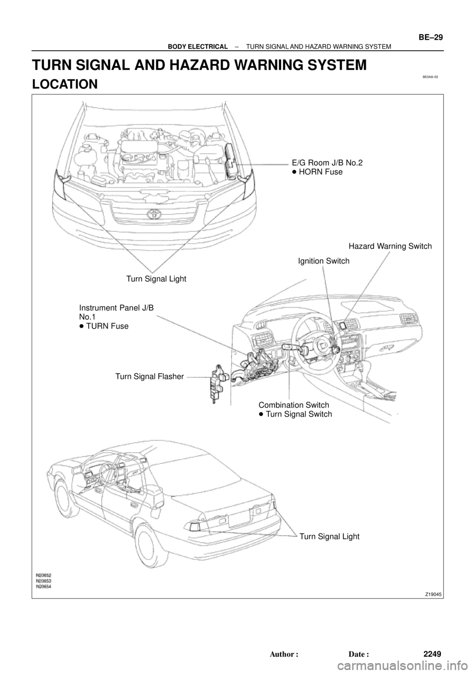
E/G Room J/B No.2
� HORN Fuse
Turn Signal Light
Instrument Panel J/B
No.1
� TURN Fuse
Turn Signal Flasher
Combination Switch
� Turn Signal SwitchIgnition SwitchHazard Warning Switch
Turn Signal Light
± BODY ELECTRICALTURN SIGNAL AND HAZARD WARNING SYSTEM
BE±29
2249 Author�: Date�:
TURN SIGNAL AND HAZARD WARNING SYSTEM
LOCATION
Page 611 of 4592

N20140
1 2 3
4
5 6 7 8 9 10
BE±30
± BODY ELECTRICALTURN SIGNAL AND HAZARD WARNING SYSTEM
2250 Author�: Date�:
INSPECTION
1")
BE0A9±02
N20150
Right
Left
2 31
BE1843
1 23
Turn Signal Light Bulbs (21 W)
N20140
1 2 3
4
5 6 7 8 9 10
BE±30
± BODY ELECTRICALTURN SIGNAL AND HAZARD WARNING SYSTEM
2250 Author�: Date�:
INSPECTION
1. INSPECT TURN SIGNAL SWITCH CONTINUITY
Switch positionTester connectionSpecified condition
Left turn1 ± 2Continuity
Neutral±No continuity
Right turn2 ± 3Continuity
If continuity is not as specified, replace the switch.
2. INSPECT TURN SIGNAL FLASHER OPERATION
(a) Connect the positive (+) lead from the battery to terminal
2 and the negative (±) lead to terminal 3.
(b) Connect the 2 turn signal light bulbs in parallel to each
other to terminals 1 and 3, check that the bulbs flash.
HINT:
The turn signal lights should flash 60 to 120 times per minute.
If one of the front or rear turn signal lights has an open circuit,
the number of flashes will be more than 140 per minute.
If operation is not as specified, replace the flasher.
3. INSPECT HAZARD WARNING SWITCH CONTINUITY
Switch positionTester connectionSpecified condition
Switch OFF7 ± 10Continuity
Switch ON5 ± 6 ± 9
7 ± 8Continuity
Illumination circuit2 ± 3Continuity
If continuity is not as specified, replace the switch.
Page 625 of 4592
BE0AI±03
Z19050
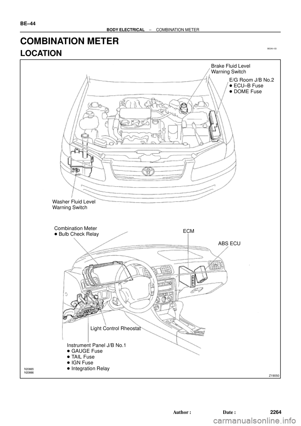
Brake Fluid Level
Warning Switch
E/G Room J/B No.2
� ECU±B Fuse
� DOME Fuse
Washer Fluid Level
Warning Switch
Combination Meter
� Bulb Check RelayECM
ABS ECU
Light Control Rheostat
Instrument Panel J/B No.1
� GAUGE Fuse
� TAIL Fuse
� IGN Fuse
� Integration Relay BE±44
± BODY ELECTRICALCOMBINATION METER
2264 Author�: Date�:
COMBINATION METER
LOCATION
Page 626 of 4592
Z19055
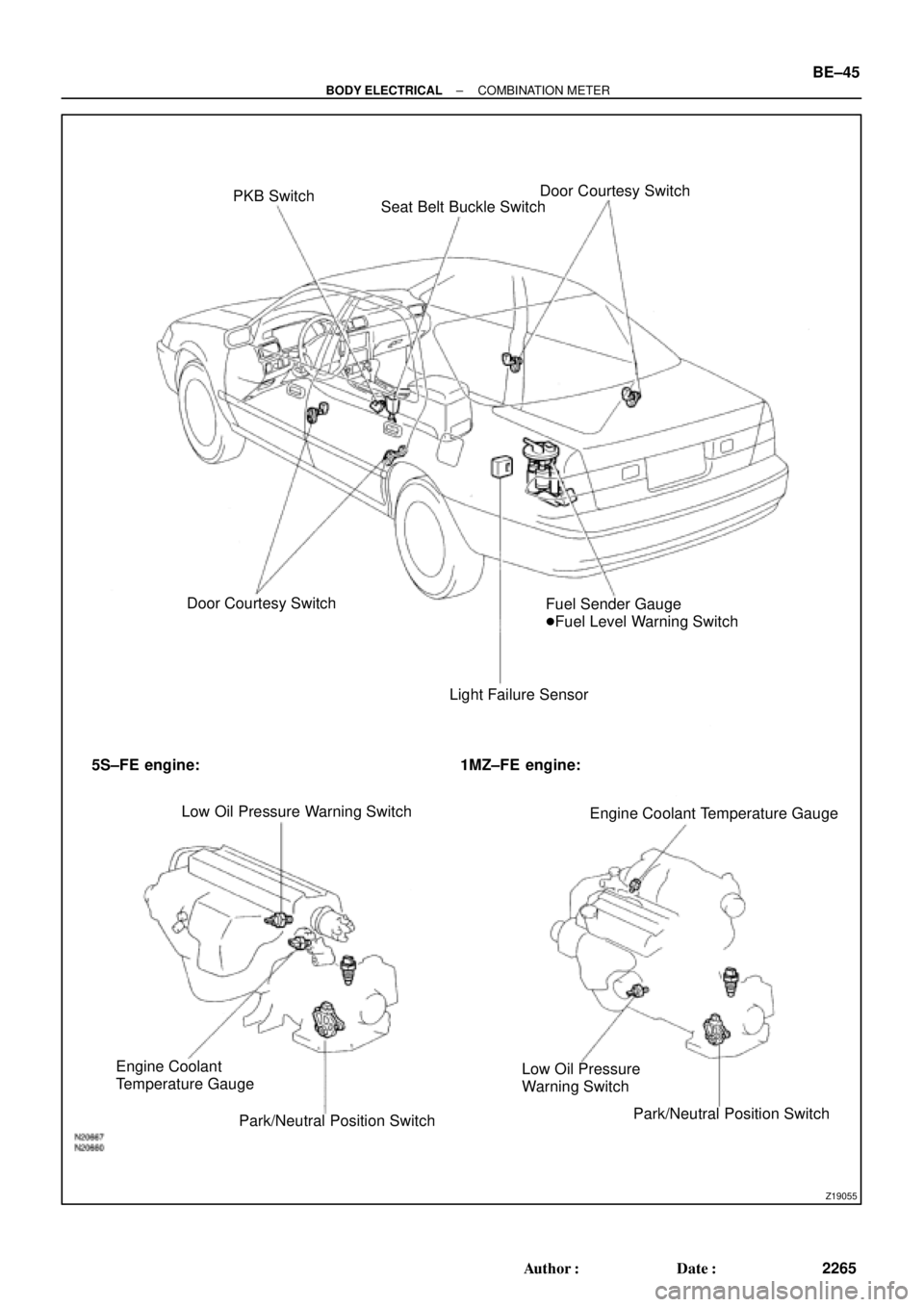
PKB Switch
Seat Belt Buckle SwitchDoor Courtesy Switch
Door Courtesy Switch
Light Failure SensorFuel Sender Gauge
�Fuel Level Warning Switch
5S±FE engine: 1MZ±FE engine:
Low Oil Pressure Warning Switch
Engine Coolant Temperature Gauge
Engine Coolant
Temperature Gauge
Park/Neutral Position SwitchLow Oil Pressure
Warning Switch
Park/Neutral Position Switch
± BODY ELECTRICALCOMBINATION METER
BE±45
2265 Author�: Date�:
Page 627 of 4592

BE0AJ±03
Z18937
Connector ºAº Connector ºBº Connector ºCº
Connector ºAº
Connector ºBº
Connector ºCº
J±13±1±A J±16±1 J±13±1
1 2 3 4 5 6 7 8 9 10 11 12 1314 15 16 1 234 56 78 910111213 1 23456 78910111213
C7
C5
A2 B3
A1
C8
B15
C6
B6
A4
C4
B5
C10 B14
A13
B2
C1
B1
C9
A6
A11
A7
A10
A8
A9
C13
B8
B11
B12A5
C11
B4
B16 C2
A12
A3
B7
C3
C12
B9
B10
B13 F
E
T
S
ODOMETER
Fuel Level Warning
Seat Belt Warning
ABS Warning
Low Oil Pressure Warning
Cruise Control Indicator
Malfunction Indicator
O/D OFF Indicator
Light Failure Warning
Brake Warning
SLIP Indicator
TRAC Indicator
Washer Level Warning
Discharge Warning
Right Turn Indicator
Left Turn Indicator
Security Indicator
L
2
D
N
R
P
Illumination
Hi±Beam Indicator
Open Door Warning
SRS Warning
: Fuel Gauge
: Engine Coolant Temperature Gauge
: Tachometer
: Speedometer
No.
A
B
C1
2
3
4
5
6
7 8
9
10
11
12 13
14
15
16
2 3
4
5
6
7 8
9
10
11 12
131
2
3
4 5
6
7
8
9
10
11
12
13
F
E
T
SEngine coolant temperature sender gauge
Ground
Light failure sensor
Integration relay
Traction ECU
Park/neutral position switch (A/T)
O/D OFF switch (A/T)
IGN fuse
Turn signal switch
ST relay
Fuel sender gauge
Generator
Oil pressure switch
Fuel sender gauge
Parking brake switch and brake fluid level warning switch
Headlight dimmer switch
Headlight dimmer switch
Door courtesy switch
DOME fuse
ECU±B fuse
Airbag sensor assembly
ECM
No.1 Vehicle speed sensor Ground
Turn signal switch ECM
Traction ECU
ABS ECU
Ground No.1 Vehicle speed sensor
GAUGE fuse
Igniter
Security ECU
Cruise control ECU
Washer fluid level warning switch
Light control rheostat
TAIL fuse Park/neutral position switch (A/T) Park/neutral position switch (A/T) Park/neutral position switch (A/T) Park/neutral position switch (A/T)
Park/neutral position switch (A/T)Wire Harness Side
Bulb Check
Relay
N20107 N201081
BE±46
± BODY ELECTRICALCOMBINATION METER
2266 Author�: Date�:
CIRCUIT
Page 630 of 4592

N20161
F
1/2
E1
2 3
Z05730 1
3
42
5
BE1217 Ie±5±1±A
BatteryWarning Light
Ignition
Switch
N20213
1 3
N20214
1
3
N20215
Engine coolant temperature gauge
Ignition
Switch
BatterySender
Gauge
± BODY ELECTRICALCOMBINATION METER
BE±49
2269 Author�: Date�:
6. INSPECT FUEL SENDER GAUGE RESISTANCE
Measure the resistance between terminals 2 and 3 for each
float position.
Float position mm (in.)Resistance (W)
F: Approx. ±91.1 (±3.587)Approx. 3.0
1/2: Approx. ±34.2 (±1.346)Approx. 31.7
E: Approx. 30.8 (1.213)Approx. 110.0
If resistance value is not as specified, replace the sender
gauge.
7. INSPECT FUEL LEVEL WARNING LIGHT
(a) Disconnect the connector from the sender gauge.
(b) Connect terminals 1 and 3 on the wire harness side con-
nector.
(c) Turn the ignition switch ON, check that the warning light
lights up.
If the warning light does not light up, test the bulb or inspect wire
harness.
8. INSPECT FUEL LEVEL WARNING SWITCH
(a) Apply battery positive voltage between terminals 1 and 3
through a 3.4±W test bulb, check that the bulb lights up.
HINT:
It takes a short time for the bulb to light up.
(b) Submerge the switch in fuel, check that the bulb goes out.
If operation is not as specified, replace the sender gauge.
9. INSPECT ENGINE COOLANT TEMPERATURE RE-
CEIVER GAUGE OPERATION
(a) Disconnect the connector from the sender gauge.
(b) Turn the ignition switch ON and check that the receiver
gauge needle indicates COOL.
Page 631 of 4592

N20216
C
B
A
N21646
Z14205
Warning Light
Ignition
Switch
Battery
1 BE±50
± BODY ELECTRICALCOMBINATIO")
Z15788
Engine coolant temperature gauge
Ignition
Switch
BatteryWire Harness SideTest Bulb
(3.4 W)
N20216
C
B
A
N21646
Z14205
Warning Light
Ignition
Switch
Battery
1 BE±50
± BODY ELECTRICALCOMBINATION METER
2270 Author�: Date�:
(c) Ground terminal on the wire harness side connector
through a 3.4±W test bulb.
(d) Turn the ignition switch ON, and check that the bulb lights
up and the receiver gauge needle moves to the hot side.
If operation is as specified, replace the sender gauge.
Then, recheck the system.
If operation is not as specified, measure the receiver gauge re-
sistance.
10. INSPECT ENGINE COOLANT TEMPERATURE RE-
CEIVER GAUGE RESISTANCE
Measure the resistance between terminals.
Tester connectionResistance (W) *
A ± BApprox. 175.7
A ± CApprox. 54.0
B ± CApprox. 229.7
*: This circuit includes the diode.
HINT:
Connect the test leads so that the current from the ohmmeter
can flow according to the above order.
If resistance value is not as specified, replace the receiver
gauge.
11. INSPECT ENGINE COOLANT TEMPERATURE SEND-
ER GAUGE RESISTANCE
Measure the resistance between the terminal and gauge body.
Temperature °C (°F)Resistance (W)
50 (122.0)274
120 (248.0)26.4
If resistance value is not as specified, replace the engine cool-
ant temperature sender gauge.
12. INSPECT LOW OIL PRESSURE WARNING LIGHT
(a) Disconnect the connector from the warning switch and
ground terminal on the wire harness side connector.
(b) Turn the ignition switch ON and check that the warning
light lights up.
If the warning light does not light up, test the bulb.
Page 632 of 4592

N06640
BE1217
Warning Light
Ignition
Switch
Battery
N02346
OFF
ON
1 2
N01212
BE1217
Warning Light
Ignition
Switch
Battery
± BODY ELECTRICALCOMBINATION METER
BE±51
2271 Author�: Date�:
13. INSPECT LOW OIL PRESSURE SWITCH
(a) Disconnect the connector from the switch.
(b) Check that continuity exists between terminal and ground
with the engine stopped.
(c) Check that no continuity exists between terminal and
ground with the engine running.
HINT:
Oil pressure should be over 24.5 kPa (0.25 kgf/cm
2, 3.55 psi).
If operation is not as specified, replace the switch.
14. INSPECT BRAKE SYSTEM WARNING LIGHT
(a) Disconnect the connector from the brake fluid warning
switch.
(b) Release the parking brake pedal.
(c) Connect the terminals on the wire harness side of the lev-
el warning switch connector.
(d) Start the engine, check that the warning light lights up.
If the warning light does not light up, test the bulb or wire har-
ness.
15. INSPECT BRAKE FLUID LEVEL WARNING SWITCH
(a) Remove the reservoir tank cap and strainer.
(b) Disconnect the connector.
(c) Check that no continuity exists between the terminals with
the switch OFF (float up).
(d) Use syphon, etc. to take fluid out of the reservoir tank.
(e) Check that continuity exists between the terminals with
the switch ON (float down).
(f) Pour the fluid back in the reservoir tank.
If operation is not as specified, replace the switch.
16. INSPECT PARKING BRAKE SWITCH
(a) Check that continuity exists between the terminal and
switch body with the switch ON (switch pin released).
(b) Check that no continuity exists between the terminal and
switch body with the switch OFF (switch pin pushed in).
If operation is not as specified, replace the switch or inspect
ground point.
17. INSPECT WASHER FLUID LEVEL WARNING LIGHT
(a) Disconnect the connectors from the level warning switch
and parking brake switch.
(b) Connect terminals on the wire harness side connector of
the level warning switch connector.
(c) Remove the GAUGE fuse and turn the ignition switch ON,
and check that the warning light comes on.
If the warning light does not light up, test the bulb.