Page 1322 of 4592
A03017
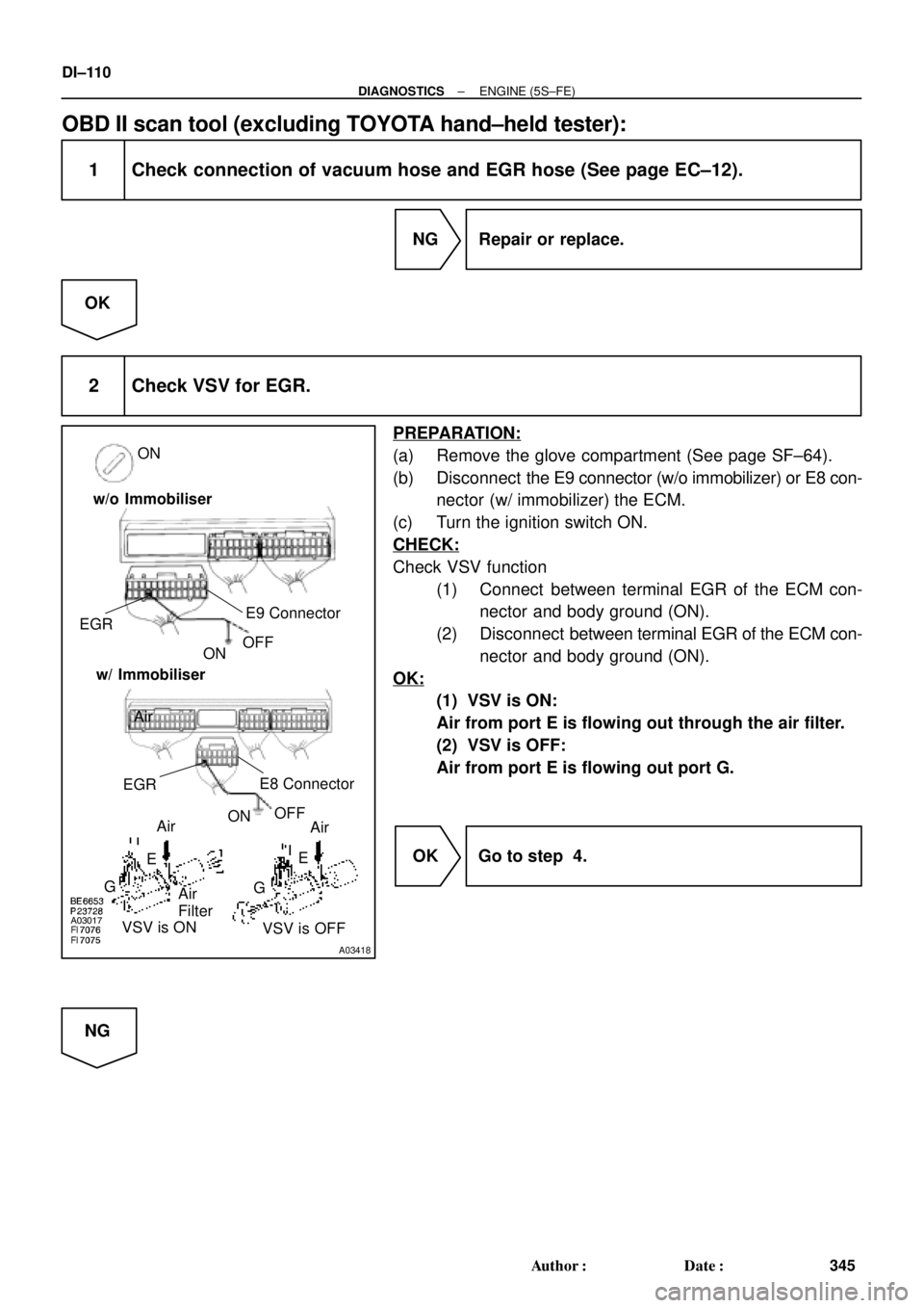
A03418
ON
E9 Connector
EGR
OFF
Air
FilterON
Air
Air
E
G E
VSV is ON
VSV is OFF Air
G w/o Immobiliser
w/ Immobiliser
OFF
ON EGR
E8 Connector
DI±110
± DIAGNOSTICSENGINE (5S±FE)
345 Author�: Date�:
OBD II scan tool (excluding TOYOTA hand±held tester):
1 Check connection of vacuum hose and EGR hose (See page EC±12).
NG Repair or replace.
OK
2 Check VSV for EGR.
PREPARATION:
(a) Remove the glove compartment (See page SF±64).
(b) Disconnect the E9 connector (w/o immobilizer) or E8 con-
nector (w/ immobilizer) the ECM.
(c) Turn the ignition switch ON.
CHECK:
Check VSV function
(1) Connect between terminal EGR of the ECM con-
nector and body ground (ON).
(2) Disconnect between terminal EGR of the ECM con-
nector and body ground (ON).
OK:
(1) VSV is ON:
Air from port E is flowing out through the air filter.
(2) VSV is OFF:
Air from port E is flowing out port G.
OK Go to step 4.
NG
Page 1346 of 4592
A00472
ON
FE
G
FE
G
VSV is ON
VSV is OFF
DI±134
± DIAGNOSTICSENGINE (5S±FE)
369 Author�: Date�:
10 Check the VSV for vapor pressure sensor.
PREPARATION:
(a) Connect the TOYOTA hand±held tester to the DLC3.
(b) Turn the ignition switch ON and push the OBD II scan tool
or TOYOTA hand±held tester main switch ON.
(c) Select the ACTIVE TEST mode on the TOYOTA hand±
held tester.
CHECK:
Check the VSV operation when it is operated by TOYOTA
hand±held tester.
OK:
(1) VSV is ON:
Air from port E is flowing out through port F.
(2) VSV is OFF:
Air from port E is flowing out through port G.
OK Go to step 13.
NG
11 Check operation of VSV for vapor pressure sensor (See page SF±47).
OK Gp to step 12.
NG
Replace VSV charcoal canister, and then clean the vacuum hoses between charcoal canister and
VSV for vapor pressure sensor, and VSV for vapor pressure sensor and vapor pressure sensor.
Page 1407 of 4592

DI078±08
Vehicle Brought to Workshop
Customer Problem Analysis P. DI±196
Problem Symptom Confirmation
If the engine does not start, perform steps 10 and 12 firstConnect the OBD II scan tool or TOYOTA hand±held tester to DLC3 P. DI±197
If the display indicates a communication fault in the tool, inspect DLC3 P. DI±197
Check DTC and Freezed Frame Data (Precheck)
Record or Print DTC and Freezed Frame Data P. DI±197
Clear DTC and Freezed Frame Data P. DI±197
Visual Inspection
Setting the Check Mode Diagnosis P. DI±197
Symptom Simulation P. IN ± 23
DTC Chart P. DI±211
Problem Symptoms Table P. DI±221
Circuit Inspection P. DI±222
Adjustment, Repair
DTC Check P. DI±197
Titles insideare titles of pages in
in the bottom portion. See the indicated
pages for detailed explanations.this manual with the page number indicated
Malfunction
occurs.Malfunction does not occur.
Parts Inspection
Check for Intermittent Problems P. DI±197
Identification of Problem
Confirmation Test
End 1
2
3
4
5
6
7
108
9
11
12
13
15 14
16
Normal Malfunction code.
17Basic Inspection P. DI±197
± DIAGNOSTICSENGINE (1MZ±FE)
DI±195
430 Author�: Date�:
ENGINE (1MZ±FE)
HOW TO PROCEED WITH TROUBLESHOOTING
Troubleshoot in accordance with the procedure on the following page.
Page 1451 of 4592

DI±239
474 Author�: Date�:
DTC P0120 Th")
P24296
ECM
Throttle Position
Sensor
VC
VTA1
E2
S05019
ECM
1
3
25 V
VC
VTA1
E2 Y
L
BR Throttle Position Sensor
E102
23
18 E10
E10
± DIAGNOSTICSENGINE (1MZ±FE)
DI±239
474 Author�: Date�:
DTC P0120 Throttle/Pedal Position Sensor/Switch ºAº
Circuit Malfunction
CIRCUIT DESCRIPTION
The throttle position sensor is mounted in the throttle body and
detects the throttle valve opening angle. When the throttle valve
is fully closed, a voltage of approximately 0.7 V is applied to ter-
minal VTA of the ECM. The voltage applied to the terminals VTA
of the ECM increases in proportion to the opening angle of the
throttle valve and becomes approximately 2.7 ~ 5.2 V when the
throttle valve is fully opened. the ECM judges the vehicle driving
conditions from these signals input from terminals VTA and
uses them as one of the conditions for deciding the air±fuel ratio
correction, power increase correction and fuel±cut control etc.
DTC No.DTC Detecting ConditionTrouble Area
P0120
Condition (a) or (b) continues:
(a) VTA
0.1 V
(b) VTA
4.9 V
�Open or short in throttle position sensor circuit
�Throttle position sensor
�ECM
HINT:
After confirming DTC P0120, use the OBD II scan tool or TOYOTA hand±held tester to confirm the throttle
valve opening percentage and closed throttle position switch condition.
Throttle valve opening position
expressed as percentage
Trouble Area
Throttle valve fully closedThrottle valve fully open
Trouble Area
0 %0 %VC line open
VTA line open or short
Approx. 100 %Approx. 100 %E2 line open
WIRING DIAGRAM
DI07K±06
Page 1599 of 4592

Record or Print DTC and Freeze Frame Data P.
DI±389
Clear DTC and Freeze Frame Data P. DI�")
DI02U±02
Vehicle Brought to Workshop
Customer Problem Analysis
Check DTC and Freeze Frame Data (Precheck)
Record or Print DTC and Freeze Frame Data P.
DI±389
Clear DTC and Freeze Frame Data P. DI±389
Visual Inspection
Setting the Check Mode Diagnosis P.
DI±389
1
Items insideare titles of pages in this manual, with the
page number indicated in the bottom portion. See the indicated
pages for detailed explanations.
P.
DI±388
Connect an OBD II scan tool or TOYOTA hand±held tester to DLC3.
If the display shows ºUNABLE TO CONNECT TO VEHICLEº when you have connected the
scan tool / TOYOTA hand±held tester, inspect DLC3 P.
DI±389
2
3
4
5
6
Symptom does not occur
Problem Symptom Confirmation8
7Symptom Simulation
P.
IN±21Symptom occurs
DTC CheckP. DI±389OK Code11Preliminary Check
P.
DI±389
DTC Chart
P. DI±401Mechanical System Test
P.
DI±389
Manual Shifting Test
P.
DI±389 OK
OK
Chapter 1
(Electronic)Chapter 2
(On±Vehicle)
P.
DI±405 OK
Chapter 3
(Off±Vehicle)OK Problem Symptoms Table± P. DI±405
Circuit
Inspection�O/D Cancel Signal Check
�O/D Main Switch & O/D OFF Indica-
tor Light Circuit Check
NG
Parts Inspection
NG
NGNG
Identification of ProblemRepairConfirmation TestEnd
NG
NG
12NG
13
14
15
16 17 9
10
P. DI±405P. DI±405
P. DI±428 to DI±431
± DIAGNOSTICSAUTOMATIC TRANSAXLE (A140E)
DI±387
622 Author�: Date�:
AUTOMATIC TRANSAXLE (A140E)
HOW TO PROCEED WITH TROUBLESHOOTING
Page 1603 of 4592

DI±391
626 Author�: Date�:
2. INSPECT DIAGNOSIS (NORMAL MODE)
(a) Check the MIL.
(1) The MIL comes on when the ig")
FI0534
S05335
TOYOTA hand±held tester
DLC3
± DIAGNOSTICSAUTOMATIC TRANSAXLE (A140E)
DI±391
626 Author�: Date�:
2. INSPECT DIAGNOSIS (NORMAL MODE)
(a) Check the MIL.
(1) The MIL comes on when the ignition switch is turned
ON and the engine is not running.
HINT:
If the MIL does not light up, troubleshoot the combination meter
(See page BE±47).
(2) When the engine is started, the MIL should go off.
If the lamp remains on, the diagnosis system has
detected a malfunction or abnormality in the sys-
tem.
(b) Check the DTC.
NOTICE:
(TOYOTA hand±held tester only): When the diagnostic sys-
tem is switched from normal mode to check mode, it erases
all DTCs and freeze frame data recorded in normal mode.
So before switching modes, always check the DTCs and
freeze frame data, and note them down.
(1) Prepare an OBD II scan tool (complying with SAE
J1978) or TOYOTA hand±held tester.
(2) Connect the OBD II scan tool or TOYOTA hand±
held tester to DLC3 at the lower portion of the instru-
ment panel.
(3) Turn the ignition switch ON and turn the OBD II scan
tool or TOYOTA hand±held tester switch ON.
(4) Use the OBD II scan tool or TOYOTA hand±held
tester to check the DTCs and freeze frame data and
note them down (For operating instructions, see the
OBD II scan tool's instruction book).
(5) See page DI±401 to confirm the details of the DTCs.
NOTICE:
When simulating symptoms with an OBD II scan tool (ex-
cluding TOYOTA hand±held tester) to check the DTCs, use
normal mode. For codes on the DTCs chart subject to º2
trip detection logicº, turn the ignition switch off after the
symptoms have been simulated the 1st time. Then repeat
the simulation process again. When the program has
DTCs, the DTCs are recorded in the ECM.
Page 1648 of 4592

Record or Print DTC and Freezed Frame Data P.
DI±438
Clear DTC and Freezed Frame Data P.")
DI02C±02
Vehicle Brought to Workshop
Customer Problem Analysis
Check DTC and Freezes Frame Data (Pre±check)
Record or Print DTC and Freezed Frame Data P.
DI±438
Clear DTC and Freezed Frame Data P. DI±449
Visual Inspection
Setting the Check Mode Diagnosis P.
DI±438
1
Items insideare titles of pages in this manual, with the
page number indicated in the bottom portion. See the indicated
pages for detailed explanations.
Connect an OBD II scan tool or TOYOTA hand±held tester to DLC3.
If the display shows ºUNABLE TO CONNECT TO VEHICLEº when you have connected the
scan tool / TOYOTA hand±held tester, inspect DLC3 P.
DI±438
2
3
4
5
6
symptom does not occur
Problem Symptom Confirmation8
7Symptom Simulation
P.
IN±21symptom occur
DTC CheckP. DI±438OK Code11Preliminary Check
P.
DI±438
DTC Chart
P. DI±449Mechanical System Test
P.
DI±438
Manual Shifting Test
P.
DI±438 OK
OK
Chapter 1
(Electronic)Chapter 2
(On±Vehicle)
P.
DI±453 OK
Chapter 3
(Off±Vehicle)OK Matrix Chart of Problem Symptoms ± P. DI±453
Circuit
Inspection�Main Throttle Signal Check
�Stop Light Signal Check
NG
Parts Inspection
NG
NGNG
Identification of ProblemRepairConfirmation TestEnd
NG
NG
12NG
13
14 15
16 17 9
10
P. DI±453P. DI±453
P. DI±484 to DI±487 P. DI±437 DI±436
± DIAGNOSTICSAUTOMATIC TRANSAXLE (A541E)
671 Author�: Date�:
AUTOMATIC TRANSAXLE (A541E)
HOW TO PROCEED WITH TROUBLESHOOTING
Page 2152 of 4592

DI00F±10
Vehicle Brought to Workshop
Customer Problem Analysis P. DI±2
Problem Symptom Confirmation
If engine does not start perform steps 10 and 12 firstConnect OBD II scan tool or TOYOTA hand±held tester to DLC3 P. DI±3
If display indicates a communication fault in tool, inspect DLC3 P. DI±3
Check DTC and Freezed Frame Data (Precheck)
Record or Print DTC and Freezed Frame Data P. DI±3
Clear DTC and Freezed Frame Data P. DI±3
Visual Inspection
Setting Check Mode Diagnosis P. DI±3
Symptom Simulation P. IN±19
Basic Inspection P. DI±3DTC Chart P. DI±3
Problem Symptoms Table P. DI±21
Circuit Inspection P. DI±22
Adjustment, Repair
DTC Check P. DI±3
Titles insideare titles of pages in
in the bottom portion. See the indicated
pages for detailed explanations.this manual with the page number indicated
Malfunction
occurs.Malfunction does not occur.
Parts Inspection
Check for Intermittent Problems P. DI±3
Identification of Problem
Confirmation Test
End 1
2
3
4
5
6
7
108
9
11
12
13
15 14
16
Normal Malfunction code.
17
± DIAGNOSTICSENGINE
DI±1
71 Author�: Date�:
ENGINE
HOW TO PROCEED WITH TROUBLESHOOTING
Troubleshoot in accordance with the procedure on the following page.