Page 839 of 4592

Will you register the
next key?
No Ye s
Insert already registered master key in the key
cylinder
Depress and release the acceleration pedal 4
times.
Depress and release the brake pedal 5 times,
and remove the master key.
Insert key to be registered in key cylinder.
Depress and release the acceleration pedal 1
time. (Security indicator blinks)
The registration mode completes when pulling
out the key within 10sec. and the brake pedal is
depressed or after indicator is off 10 sec. pass. Within 10 sec.Within 15 sec.
Within 20 sec.
Within 10 sec.
Within 10 sec.
After 60 sec. additional sub±key is registered.
(Security indicator is OFF)
± BODY ELECTRICALENGINE IMMOBILISER SYSTEM
BE±123
2343 Author�: Date�:
3. REGISTRATION ADDITIONAL OF SUB±KEY
There are 2 ways for registration of additional sub±key, one is depressing brake pedal and acceleration ped-
al and the other is using TOYOTA hand±held tester.
HINT:
�It is possible top register up to 3 sub±key codes including the already registered key code.
�When any operation time described below is over, registration mode completes.
�When the next procedure is performed while the timer is working, the timer completes counting time,
then next timer starts.
(1) Depressing brake pedal and acceleration pedal:
Page 840 of 4592
Will you register the
next key?
Insert already registered master key in the key cylinder.
Listing TOYOTA hand±held tester select sub±key regis-
tration.
Remove the master key.
Insert key to be registered in key cylinder.
(Security indicator blinks)
After 60 sec., additional master key is registered.
(Security indicator OFF)
The registration mode completes when pulling out the key
within 10sec. and the brake pedal is depressed or after in-
dicator is off 10 sec. pass.No Ye s Within
10 sec.Within 120 sec.
Within 20 sec.
Within 10 sec.
Within 10 sec.
BE±124
± BODY ELECTRICALENGINE IMMOBILISER SYSTEM
2344 Author�: Date�:
(2) Using TOYOTA hand±held tester:
Page 841 of 4592

4. Remove the mast")
1. Insert master key in the key cylinder.
2. Depress and release the acceleration pedal 6 times.
3. Depress and release the brake pedal 7 times.
(Security indicator blinks)
4. Remove the master key.
(Security indicator blinks)
HINT:
When the key cannot be pulled out in the step 4, key code deletion is canceled.
(Security indicator is OFF) END
(Key code erasured)
Within 15 sec.
Within 20 sec.
Within 10 sec.
± BODY ELECTRICALENGINE IMMOBILISER SYSTEM
BE±125
2345 Author�: Date�:
4. ERASURE OF TRANSPONDER KEY CODE
There are 2 ways for erasure of transponder key code, one is depressing brake pedal and acceleration pedal
and the other is using TOYOTA hand±held tester.
NOTICE:
All other master and sub±key codes are deleted leaving the master key code to use the operation.
When using the key which was used before deleting, it is necessary to register the code again.
HINT:
�When any operation time described below is over, registration mode completes.
�When the next procedure is performed while the timer is working, the timer completes counting time,
then next timer starts.
(1) Depressing brake pedal and acceleration pedal:
Page 922 of 4592
 Remove the bolt, nut, screw and the instrument panel as-
sembly.
23. REMOVE INSTRUMENT PANEL BRACES
(a) Remove the w")
N20994
N20995
N20996
N20997
BO±78
± BODYINSTRUMENT PANEL
2426 Author�: Date�:
(f) Remove the bolt, nut, screw and the instrument panel as-
sembly.
23. REMOVE INSTRUMENT PANEL BRACES
(a) Remove the wire brackets and connector.
(b) Remove the bolt and connector from the No.1 instrument
panel brace.
(c) w/ Wireless Control:
Remove the nut and the wireless control unit from the
No.1 instrument panel brace.
(d) Remove the nut holding the radio antenna to the No.2
instrument panel brace.
(e) Remove a nut and brace mount bracket.
(f) Remove the 6 nuts, 2 bolts and No.1 and No.2 instrument
panel braces.
24. REMOVE INSTRUMENT PANEL REINFORCEMENT
(a) Remove the connectors from the steering column tube.
(b) Remove the 4 wire brackets and connectors.
(c) Remove the 2 nuts and bolt holding the No.1 Junction Box
(J/B) to the reinforcement.
(d) Remove the 4 nuts and the steering column from the rein-
forcement.
(e) Remove the brake pedal spring from the reinforcement
and brake pedal.
(f) Remove the 4 nuts, 3 bolts and the reinforcement.
Page 969 of 4592
 if it has been use")
BO0NG±01
BO0632
BO0633
15°
45° BO±124
± BODYSEAT BELT
2472 Author�: Date�:
INSPECTION
CAUTION:
Replace the seat belt assembly (outer belt, inner belt, bolts,
nuts or sill±bar) if it has been used in a severe impact. The
entire assembly should be replaced even if damage is not
obvious.
1. All Seat Belt:
RUNNING TEST (IN SAFE AREA)
(a) Fasten the front seat belts.
(b) Drive the car at 10 mph (16 km/h) and slam on the brakes.
Check that the belt locks and cannot be extended at this
time.
HINT:
Conduct this test in a safe area. If the belt does not lock, remove
the belt mechanism assembly and conduct the following static
check. Also, whenever installing a new belt assembly, verify the
proper operation before installation.
2. Driver 's Seat Belt (ELR):
STATIC TEST
(a) Make sure that the belt locks when pulled out quickly.
(b) Remove the locking retractor assembly.
(c) Tilt the retractor slowly.
(d) Make sure that the belt can be pulled out at a tilt of 15 de-
grees or less, and cannot be pulled out over 45 degrees
of tilt.
If a problem is found, replace the assembly.
3. Front RH Seat Belt and Rear Seat Belt (ALR/ELR):
STATIC TEST
(a) Make sure that the belt locks when pulled out quickly.
(b) Remove the locking retractor assembly.
(c) Pull out the whole belt and measure the length of the
whole belt.
Then retract the belt slightly and pull it out again
(d) Make sure that the belt cannot be extended further.
If a problem is found, replace the assembly.
Page 981 of 4592
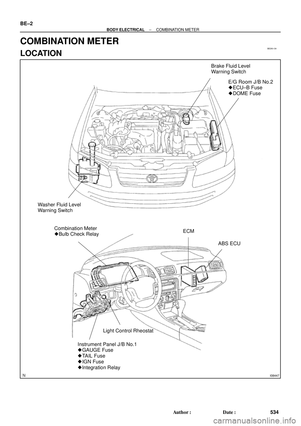
BE0AI±04
I08447
Brake Fluid Level
Warning Switch
E/G Room J/B No.2
� ECU±B Fuse
� DOME Fuse
Washer Fluid Level
Warning Switch
Combination Meter
� Bulb Check RelayECM
ABS ECU
Light Control Rheostat
Instrument Panel J/B No.1
� GAUGE Fuse
� TAIL Fuse
� IGN Fuse
� Integration Relay
BE±2
± BODY ELECTRICALCOMBINATION METER
534 Author�: Date�:
COMBINATION METER
LOCATION
Page 983 of 4592

BE0AJ±04
Z18937
Connector ºAº Connector ºBº Connector ºCº
Connector ºAº
Connector ºBº
Connector ºCº
J±13±1±A J±16±1 J±13±1
1 2 3 4 5 6 7 8 9 10 11 12 1314 15 16 1 234 56 78 910111213 1 23456 78910111213
C7
C5
A2 B3
A1
C8
B15
C6
B6
A4
C4
B5
C10 B14
A13
B2
C1
B1
C9
A6
A11
A7
A10
A8
A9
C13
B8
B11
B12A5
C11
B4
B16 C2
A12
A3
B7
C3
C12
B9
B10
B13 F
E
T
S
ODOMETER
Fuel Level Warning
Seat Belt Warning
ABS Warning
Low Oil Pressure Warning
Cruise Control Indicator
Malfunction Indicator
O/D OFF Indicator
Light Failure Warning
Brake Warning
SLIP Indicator
TRAC Indicator
Washer Level Warning
Discharge Warning
Right Turn Indicator
Left Turn Indicator
Security Indicator
L
2
D
N
R
P
Illumination
Hi±Beam Indicator
Open Door Warning
SRS Warning
: Fuel Gauge
: Engine Coolant Temperature Sender Gauge
: Tachometer
: Speedometer
No.
A
B
C1
2
3
4
5
6
7 8
9
10
11
12 13
14
15
16
2 3
4
5
6
7 8
9
10
11 12
131
2
3
4 5
6
7
8
9
10
11
12
13
F
E
T
SEngine coolant temperature sender gauge
Ground
Light failure sensor
Integration relay
Traction ECU
Park/neutral position switch (A/T)
O/D OFF switch (A/T)
IGN fuse
Turn signal switch
ST relay
ECM
Generator
Oil pressure switch
ECM
Parking brake switch and brake fluid level warning switch
Headlight dimmer switch
Headlight dimmer switch
Door courtesy switch
DOME fuse
ECU±B fuse
Airbag sensor assembly
ECM
No.1 Vehicle speed sensor Ground
Turn signal switch ECM
Traction ECU
ABS ECU
Ground No.1 Vehicle speed sensor
GAUGE fuse
Igniter
Security ECU
Cruise control ECU
Washer fluid level warning switch
Light control rheostat
TAIL fuse Park/neutral position switch (A/T) Park/neutral position switch (A/T) Park/neutral position switch (A/T) Park/neutral position switch (A/T)
Park/neutral position switch (A/T)Wire Harness Side
Bulb Check
Relay
N20107 N201081
BE±4
± BODY ELECTRICALCOMBINATION METER
CIRCUIT
Page 1013 of 4592
 if it has been used in a severe im-
pact")
BO2E1±01
BO0632
BO0633
15°
45°
± BODYSEAT BELT
BO±27
INSPECTION
CAUTION:
Replace the seat belt assembly (Outer belt, inner belt,
bolts, nuts or sill±bar) if it has been used in a severe im-
pact. The entire assembly should be replaced even if dam-
age is not obvious.
1. All seat belt:
RUNNING TEST IN SAFE AREA
(a) Fasten the front seat belts.
(b) Drive the car at 10 m/h (16 km/h) and slam on the brakes.
Check that the belt locks and cannot be extended at this
time.
HINT:
Conduct this test in a safe area. If the belt does not lock, remove
the belt mechanism assembly and conduct the following static
check. Also whenever installing a new belt assembly, verify the
proper operation before installation.
2. Driver 's seat belt (ELR):
STATIC TEST
(a) Make sure that the belt locks when pulled out quickly.
(b) Remove the locking retractor assembly.
(c) Tilt the retractor slowly.
(d) Make sure that the belt can be pulled out at a tilt of 15 de-
grees or less, and cannot be pulled out over 45 degrees
of tilt.
If a problem is found, replace the assembly.
3. Except driver's seat belt (ALR/ELR):
STATIC TEST
(a) Make sure that the belt locks when pulled out quickly.
(b) Remove the locking retractor assembly.
(c) Pull out the whole belt and measure the length of the
whole belt. Then retract the belt slightly and pull it out
again.
(d) Make sure that the belt cannot be extended further.
If a problem is found, replace the assembly.