Page 703 of 4592
Will you register the
next key?
Insert already registered master key in the key cylinder.
Listing TOYOTA hand±held tester select master key reg-
istration.
Remove the master key.
Insert key to be registered in key cylinder.
(Security indicator blinks)
After 60 sec., additional master key is registered.
(Security indicator OFF)
The registration mode completes when pulling out the key
within 10sec. and the brake pedal is depressed or after in-
dicator is off 10 sec. pass.No Ye s Within
10 sec.Within 120 sec.
Within 20 sec.
Within 10 sec.
Within 10 sec.
BE±122
± BODY ELECTRICALENGINE IMMOBILISER SYSTEM
2342 Author�: Date�:
(2) Using TOYOTA hand±held tester:
Page 704 of 4592

Will you register the
next key?
No Ye s
Insert already registered master key in the key
cylinder
Depress and release the acceleration pedal 4
times.
Depress and release the brake pedal 5 times,
and remove the master key.
Insert key to be registered in key cylinder.
Depress and release the acceleration pedal 1
time. (Security indicator blinks)
The registration mode completes when pulling
out the key within 10sec. and the brake pedal is
depressed or after indicator is off 10 sec. pass. Within 10 sec.Within 15 sec.
Within 20 sec.
Within 10 sec.
Within 10 sec.
After 60 sec. additional sub±key is registered.
(Security indicator is OFF)
± BODY ELECTRICALENGINE IMMOBILISER SYSTEM
BE±123
2343 Author�: Date�:
3. REGISTRATION ADDITIONAL OF SUB±KEY
There are 2 ways for registration of additional sub±key, one is depressing brake pedal and acceleration ped-
al and the other is using TOYOTA hand±held tester.
HINT:
�It is possible top register up to 3 sub±key codes including the already registered key code.
�When any operation time described below is over, registration mode completes.
�When the next procedure is performed while the timer is working, the timer completes counting time,
then next timer starts.
(1) Depressing brake pedal and acceleration pedal:
Page 705 of 4592
Will you register the
next key?
Insert already registered master key in the key cylinder.
Listing TOYOTA hand±held tester select sub±key regis-
tration.
Remove the master key.
Insert key to be registered in key cylinder.
(Security indicator blinks)
After 60 sec., additional master key is registered.
(Security indicator OFF)
The registration mode completes when pulling out the key
within 10sec. and the brake pedal is depressed or after in-
dicator is off 10 sec. pass.No Ye s Within
10 sec.Within 120 sec.
Within 20 sec.
Within 10 sec.
Within 10 sec.
BE±124
± BODY ELECTRICALENGINE IMMOBILISER SYSTEM
2344 Author�: Date�:
(2) Using TOYOTA hand±held tester:
Page 706 of 4592

4. Remove the mast")
1. Insert master key in the key cylinder.
2. Depress and release the acceleration pedal 6 times.
3. Depress and release the brake pedal 7 times.
(Security indicator blinks)
4. Remove the master key.
(Security indicator blinks)
HINT:
When the key cannot be pulled out in the step 4, key code deletion is canceled.
(Security indicator is OFF) END
(Key code erasured)
Within 15 sec.
Within 20 sec.
Within 10 sec.
± BODY ELECTRICALENGINE IMMOBILISER SYSTEM
BE±125
2345 Author�: Date�:
4. ERASURE OF TRANSPONDER KEY CODE
There are 2 ways for erasure of transponder key code, one is depressing brake pedal and acceleration pedal
and the other is using TOYOTA hand±held tester.
NOTICE:
All other master and sub±key codes are deleted leaving the master key code to use the operation.
When using the key which was used before deleting, it is necessary to register the code again.
HINT:
�When any operation time described below is over, registration mode completes.
�When the next procedure is performed while the timer is working, the timer completes counting time,
then next timer starts.
(1) Depressing brake pedal and acceleration pedal:
Page 711 of 4592
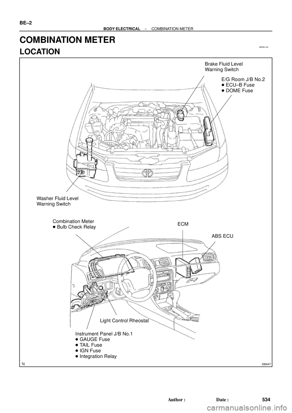
BE0AI±04
I08447
Brake Fluid Level
Warning Switch
E/G Room J/B No.2
� ECU±B Fuse
� DOME Fuse
Washer Fluid Level
Warning Switch
Combination Meter
� Bulb Check RelayECM
ABS ECU
Light Control Rheostat
Instrument Panel J/B No.1
� GAUGE Fuse
� TAIL Fuse
� IGN Fuse
� Integration Relay
BE±2
± BODY ELECTRICALCOMBINATION METER
534 Author�: Date�:
COMBINATION METER
LOCATION
Page 713 of 4592

BE0AJ±04
Z18937
Connector ºAº Connector ºBº Connector ºCº
Connector ºAº
Connector ºBº
Connector ºCº
J±13±1±A J±16±1 J±13±1
1 2 3 4 5 6 7 8 9 10 11 12 1314 15 16 1 234 56 78 910111213 1 23456 78910111213
C7
C5
A2 B3
A1
C8
B15
C6
B6
A4
C4
B5
C10 B14
A13
B2
C1
B1
C9
A6
A11
A7
A10
A8
A9
C13
B8
B11
B12A5
C11
B4
B16 C2
A12
A3
B7
C3
C12
B9
B10
B13 F
E
T
S
ODOMETER
Fuel Level Warning
Seat Belt Warning
ABS Warning
Low Oil Pressure Warning
Cruise Control Indicator
Malfunction Indicator
O/D OFF Indicator
Light Failure Warning
Brake Warning
SLIP Indicator
TRAC Indicator
Washer Level Warning
Discharge Warning
Right Turn Indicator
Left Turn Indicator
Security Indicator
L
2
D
N
R
P
Illumination
Hi±Beam Indicator
Open Door Warning
SRS Warning
: Fuel Gauge
: Engine Coolant Temperature Sender Gauge
: Tachometer
: Speedometer
No.
A
B
C1
2
3
4
5
6
7 8
9
10
11
12 13
14
15
16
2 3
4
5
6
7 8
9
10
11 12
131
2
3
4 5
6
7
8
9
10
11
12
13
F
E
T
SEngine coolant temperature sender gauge
Ground
Light failure sensor
Integration relay
Traction ECU
Park/neutral position switch (A/T)
O/D OFF switch (A/T)
IGN fuse
Turn signal switch
ST relay
ECM
Generator
Oil pressure switch
ECM
Parking brake switch and brake fluid level warning switch
Headlight dimmer switch
Headlight dimmer switch
Door courtesy switch
DOME fuse
ECU±B fuse
Airbag sensor assembly
ECM
No.1 Vehicle speed sensor Ground
Turn signal switch ECM
Traction ECU
ABS ECU
Ground No.1 Vehicle speed sensor
GAUGE fuse
Igniter
Security ECU
Cruise control ECU
Washer fluid level warning switch
Light control rheostat
TAIL fuse Park/neutral position switch (A/T) Park/neutral position switch (A/T) Park/neutral position switch (A/T) Park/neutral position switch (A/T)
Park/neutral position switch (A/T)Wire Harness Side
Bulb Check
Relay
N20107 N201081
BE±4
± BODY ELECTRICALCOMBINATION METER
CIRCUIT
Page 720 of 4592
1. Integration Relay (I/P J/B No.1)
2. Light Control Switch
3. Wire HarnessBE±1")
BE±4
± BODY ELECTRICALBODY ELECTRICAL SYSTEM
2224 Author�: Date�:
Taillight does not light.
(Headlight does not light)1. Integration Relay (I/P J/B No.1)
2. Light Control Switch
3. Wire HarnessBE±14
BE±24
±
Taillight does not light.
(Headlight is normal)
1. TAIL Fuse (I/P J/B No.1)
2. Taillight Control Relay (I/P J/B No.1)
3. Integration Relay (I/P J/B No.1)
4. Light Control Switch
5. Wire Harness±
BE±24
BE±14
BE±24
±
Only one side light does not light.1. Bulb
2. Wire Harness±
±
Rear Combination light does not light.
1. Bulb
2. Light Failure Sensor
3. Wire Harness±
BE±37
±
ºAuto Turn±off Systemº does not operate.
1. GAUGE Fuse (I/P J/B No.1)
2. Integration Relay (I/P J/B No.1)
3. Door Courtesy Switch (Driver's)
4. Wire Harness±
BE±14
BE±24
±
*Terminal L of generator and parking brake switch
TURN SIGNAL AND HAZARD WARNING SYSTEM
SymptomSuspect AreaSee page
ºHazardº and ºTurnº do not light up.
1. Hazard Warning Switch
2. Turn Signal Flasher
3. Wire HarnessBE±30
BE±30
±
The flashing frequency is abnormal.
1. Bulb
2. Turn Signal Switch
3. Wire Harness±
BE±30
±
Hazard warning light does not light up.
(Turn is normal.)1. HORN Fuse (E/G Room J/B No.2)
2. Wire Harness±
±
Hazard warning light does not light up in one direction.1. Hazard Warning Switch
2. Wire HarnessBE±30
±
*1Turn signal does not light up.
1. Ignition Switch
2. TURN Fuse (I/P J/B No.1)
3. Turn Signal Switch
4. Wire HarnessBE±14
±
BE±30
±
*2Turn signal does not light up.
1. TURN Fuse (I/P J/B No.1)
2. Turn Signal Switch
3. Wire Harness±
BE±30
±
Turn signal does not light up in one direction.1. Turn Signal Switch
2. Wire HarnessBE±30
±
Only one bulb does not light up.1. Bulb
2. Wire Harness±
±
*1: Combination meter, wiper and washer do not operate.
*
2: Combination meter, wiper and washer are normal.
INTERIOR LIGHT SYSTEM
SymptomSuspect AreaSee page
ºIlluminated Entry Systemº does not operate.
1. Door Courtesy Switch
2. Integration Relay (I/P J/B No.1)
3. Wire HarnessBE±32
BE±14
±
Only one interior light does not light up.1. Bulb
2. Wire Harness±
±
Interior light does not light up (All).1. DOME Fuse (E/G Room J/B No.2)
2. Wire Harness±
±
Page 723 of 4592

4. Wire Harness±")
± BODY ELECTRICALBODY ELECTRICAL SYSTEM
BE±7
2227 Author�: Date�:
Seat Belt warning light does not light up.
1. Bulb
2. Seat Belt Buckle Switch
3. Integration Relay (I/P J/B No.1)
4. Wire Harness±
BE±47
BE±47
±
Discharge warning light does not light up.
1. IGN Fuse (I/P J/B No.1)
2. Bulb
3. Wire Harness
4. Generator (5S±FE)
(1MZ±FE)±
±
±
CH±1
CH±1
Light Failure warning light does not light up.
1. Bulb
2. Light Failure Sensor
3. Bulb Check Relay
4. Wire Harness
5. Taillight system±
BE±37
BE±47
±
BE±24
Brake warning light does not light up.
1. Bulb
2. Parking Brake Switch
3. Brake Fluid Level Warning Switch
4. Bulb Check Relay
5. Meter Circuit Plate
6. Wire Harness±
BE±47
BE±47
BE±47
BE±46
±
SRS Warning light does not light up.
1. ECU±B Fuse (E/G Room J/B No.2)
2. Bulb
3. Airbag Sensor Assembly
4. Meter Circuit Plate
5. Wire Harness±
±
DI±626
BE±46
±
Open Door warning light does not light up.
1. DOME Fuse (E/G Room J/B No.2)
2. Bulb
3. Door Courtesy Switch
4. Meter Circuit Plate
5. Wire Harness±
±
BE±32
BE±46
±
Washer Level warning light does not light up.
1. Bulb
2. Washer Fluid Level Warning Switch
3. Meter Circuit Plate
4. Wire Harness±
BE±47
BE±46
±
COMBINATION METER
INDICATOR LIGHTS:
SymptomSuspect AreaSee page
O/D OFF indicator light does not light up.
1. Bulb
2. O/D OFF Switch (A140E)
(A541E)
3. Meter Circuit Plate
4. Wire Harness±
DI±431
DI±487
BE±46
±
Cruise Control indicator light does not light up.
1. Bulb
2. Cruise Control ECU
3. Meter Circuit Plate
4. Wire Harness±
IN±31
BE±46
±
High beam indicator light does not light up.
1. Bulb
2. Meter Circuit Plate
3. Wire Harness
4. Headlight System±
BE±46
±
BE±22
Turn indicator light does not light up.
1. Bulb
2. Meter Circuit Plate
3. Wire Harness
4. Turn Signal and Hazard Warning System±
BE±46
±
BE±29