Page 1447 of 4592

DI±235
470 Author�: Date�:")
A02020
ON
Engine Coolant Temp. Sensor
ECM
THW E2
E10
E1014
185 V
THW
E2
1 2
A00216
ON
Engine Coolant
Temp. Sensor
ECM
5 V
E2 THWE1018 14
E10
± DIAGNOSTICSENGINE (1MZ±FE)
DI±235
470 Author�: Date�:
3 Check for open in harness or ECM.
PREPARATION:
(a) Remove the glove compartment (See page SF±73).
(b) Connect between terminals THW and E2 of the ECM con-
nector.
HINT:
Engine coolant temp. sensor connector is disconnected. Be-
fore checking, do a visual and contact pressure check for the
ECM connector (See page IN±31).
(c) Turn the ignition switch ON.
CHECK:
Read temperature. value on the OBD II scan tool or TOYOTA
hand±held tester.
OK:
Temperature value: 1405C (2845F) or more
OK Open in harness between terminal E2 or THW,
repair or replace harness.
NG
Confirm good connection at ECM.
If OK, check and replace ECM.
4 Check for short in harness and ECM.
PREPARATION:
(a) Disconnect the engine coolant temp. sensor connector.
(b) Turn the ignition switch ON.
CHECK:
Read temperature value on the OBD II scan tool or TOYOTA
hand±held tester.
OK:
Temperature value: ±405C (±405F)
OK Replace engine coolant temp. sensor.
NG
Page 1448 of 4592
A02043
ON
ECM
Engine Coolant Temp. Sensor
THW
E2
E105 V
DI±236
± DIAGNOSTICSENGINE (1MZ±FE)
471 Author�: Date�:
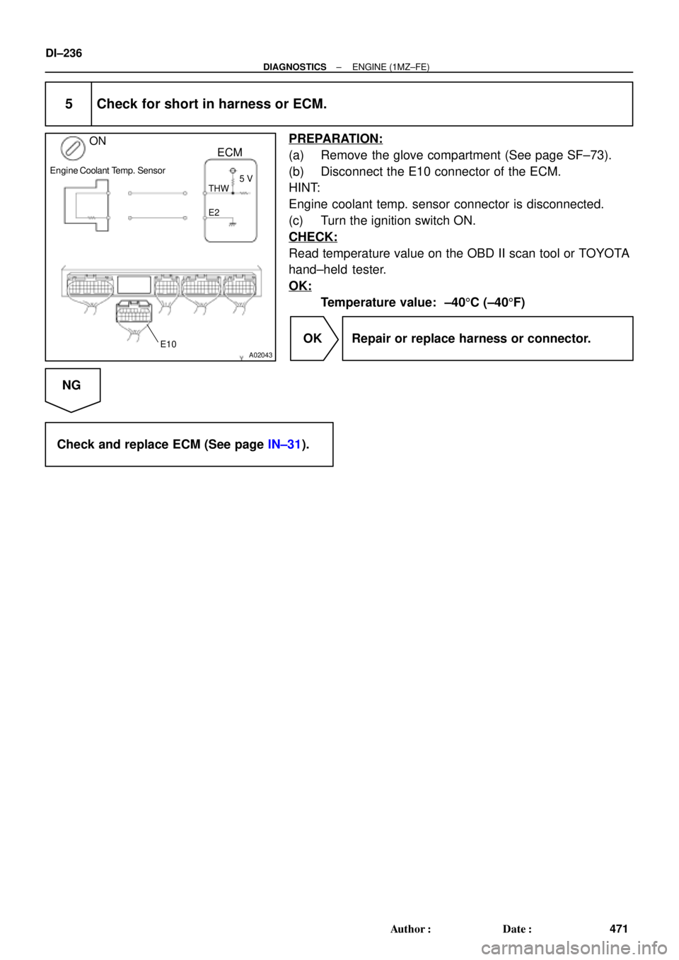
5 Check for short in harness or ECM.
PREPARATION:
(a) Remove the glove compartment (See page SF±73).
(b) Disconnect the E10 connector of the ECM.
HINT:
Engine coolant temp. sensor connector is disconnected.
(c) Turn the ignition switch ON.
CHECK:
Read temperature value on the OBD II scan tool or TOYOTA
hand±held tester.
OK:
Temperature value: ±405C (±405F)
OK Repair or replace harness or connector.
NG
Check and replace ECM (See page IN±31).
Page 1449 of 4592

DI±237
472 Author�: Date�:
DTC P0116 Engine Coolant Temp. Circuit Range/
Performance Problem
CIRCUIT DESCRIPTION
Refer to DTC P0115 (Engine Coolant Temp. Circuit Malfu")
± DIAGNOSTICSENGINE (1MZ±FE)
DI±237
472 Author�: Date�:
DTC P0116 Engine Coolant Temp. Circuit Range/
Performance Problem
CIRCUIT DESCRIPTION
Refer to DTC P0115 (Engine Coolant Temp. Circuit Malfunction) on page DI±233.
DTC No.DTC Detecting ConditionTrouble Area
If THW ±7°C (19.4°F), 20 min. or more after starting
engine, engine coolant temp. sensor value is 20°C (68°F) or
less
(2 trip detection logic)
If THW � ±7°C (19.4°F) and 10°C (50°F), 5 min. or more
after starting engine,
engine coolant temp. sensor value is 20°C (68°F) or less
(2 trip detection logic)
Engine coolant temp sensorP0116If THW � 10°C (50 °F), 2 min. or more after starting engine,
engine coolant temp. sensor value is 30°C (86°F)
(2 trip detection logic)�Engine coolant temp. sensor
�Cooling system
When THW � 35°C (95°F) or more and less than 60°C
(140°F), THA � ± 6.7°C (19.9°F) or more, when starting
engine , condition (a) and (b) continues:
(a) Vehicle speed is changing (Not stable)
(b) When starting engine, THW< 3°C (37.4°F)
(2 trip detection logic)
INSPECTION PROCEDURE
HINT:
�If DTCs P0115 (Engine Coolant Temp. Circuit Malfunction) and P0116 (Engine Coolant Temp. Circuit
Range/Performance) are output simultaneously, engine coolant temp. sensor circuit may be open.
Perform troubleshooting of DTC P0115 first.
�Read freeze frame data using TOYOTA hand±held tester or OBD II scan tool. Because freeze frame
records the engine conditions when the malfunction is detected, when troubleshooting it is useful for
determining whether the vehicle was running or stopped, the engine warmed up or not, the air±fuel
ratio lean or rich, etc. at the time of the malfunction.
1 Are there any other codes (besides DTC P0116) being output?
YES Go to relevant DTC chart.
NO
DI07J±06
Page 1450 of 4592
DI±238
± DIAGNOSTICSENGINE (1MZ±FE)
473 Author�: Date�:
2 Check thermostat (See page CO±9).
NG Replace thermostat.
OK
Replace engine coolant temp. sensor.
Page 1452 of 4592

475 Author�: Date�:
INSPECTION PROCEDURE
HINT:
�If DTCs P0110(Intake Air temp. Circuit Malfunction), P0115(Engine Coolant Temp. Circuit Malfunc-
tion), P")
FI7052
DI±240
± DIAGNOSTICSENGINE (1MZ±FE)
475 Author�: Date�:
INSPECTION PROCEDURE
HINT:
�If DTCs P0110(Intake Air temp. Circuit Malfunction), P0115(Engine Coolant Temp. Circuit Malfunc-
tion), P0120(Throttle/Pedal Position Sensor/Switch ºAº Circuit Malfunction) and P1410 are output si-
multaneously, E2 (Sensor Ground) may be open.
�Read freeze frame data using TOYOTA hand±held tester or OBD II scan tool. Because freeze frame
records the engine conditions when the malfunction is detected, when troubleshooting it is useful for
determining whether the vehicle was running or stopped, the engine warmed up or not, the air±fuel
ratio lean or rich, etc. at the time of the malfunction.
1 Connect OBD II scan tool or TOYOTA hand±held tester, and read throttle valve
opening percentage.
PREPARATION:
(a) Connect the OBD II scan tool or TOYOTA hand±held tes-
ter to DLC3.
(b) Turn the ignition switch ON and push the OBD II scan tool
or TOYOTA hand±held tester main switch ON.
CHECK:
Read the throttle valve opening percentage.
OK:
Throttle valveThrottle valve opening position
expressed as percentage
Fully openApprox. 75 %
Fully closedApprox. 10 %
OK Check for intermittent problems
(See page DI±197).
NG
Page 1456 of 4592

Platium Electrode
Heater
Coating(Cera")
P21242 FI7210
A00027
Atmosphere
CoverIdeal Air±Fuel Mixture
Air Fuel Ratio
RicherLeaner
Exhaust GasFlange
Platinum Electrode
Solid Electrolyte
(Zirconia Element)
Platium Electrode
Heater
Coating(Ceramic)
Output Voltage
DI±244
± DIAGNOSTICSENGINE (1MZ±FE)
479 Author�: Date�:
DTC P0125 Insufficient Coolant Temp. for Closed Loop
Fuel Control (Except California Spec.)
CIRCUIT DESCRIPTION
To obtain a high purification rate for the CO, HC and NOx components of the exhaust gas, a three±way
catalytic converter is used, but for the most efficient use of the three±way catalytic converter, the air±fuel
ratio must be precisely controlled so that it is always close to the stoichiometric air±fuel ratio.
The oxygen sensor has the characteristic whereby its output voltage changes suddenly in the vicinity of the
stoichiometric air±fuel ratio. This characteristic is used to detect the oxygen concentration in the exhaust
gas and provide feedback to the computer for control of the air±fuel ratio.
When the air±fuel ratio becomes LEAN, the oxygen concentration in the exhaust increases and the oxygen
sensor informs the ECM of the LEAN condition (small electromotive force: < 0.45 V).
When the air±fuel ratio is RICHER than the stoichiometric air±fuel ratio the oxygen concentration in the ex-
haust gas is reduced and the oxygen sensor informs the ECM of the RICH condition (large electromotive
force: > 0.45 V). The ECM judges by the electromotive force from the oxygen sensor whether the air±fuel
ratio is RICH or LEAN and controls the injection time accordingly. However, if malfunction of the oxygen sen-
sor causes output of abnormal electromotive force, the ECM is unable to perform accurate air±fuel ratio con-
trol.
The heated oxygen sensors include a heater which heats the zirconia element. The heater is controlled by
the ECM. When the intake air volume is low (the temperature of the exhaust gas is low) current flows to the
heater to heat the sensor for accurate oxygen concentration detection.
DTC No.DTC Detecting ConditionTrouble Area
P0125
After engine is warmed up, heated oxygen sensor (bank 1, 2
sensor 1) output does not indicate RICH (� 0.45 V ) even
once when conditions (a), (b), (c) and (d) continue for at least
2 min.:
(a) Engine speed: 1,500 rpm or more
(b) Vehicle speed: 40 � SPD and 100 km/h (25 � SPD and
62 mph)
(c) Throttle valve does not fully closed
(d) 140 sec. or more after starting engine�Fuel system
�Injector
�Ignition system
�Gas leakage on exhaust system
�Open or short in heated oxygen sensors (bank 1, 2 sensor 1)
circuit
�Heated oxygen sensors (bank 1, 2 sensor 1)
�ECM
DI07M±08
Page 1461 of 4592

Platinum
Electrode
Heater
Coating (Ceramic)
Exhaust Gas
(V)
4.0
3.8
3.6
3.4
3.2
3.0
2.8
2.6
17
Air±Fuel Ratio
2.4
16 15")
A00477
CoverAtmosphere
Platinum
Electrode
Solid Electrolyte
(Zirconia Element)
Platinum
Electrode
Heater
Coating (Ceramic)
Exhaust Gas
(V)
4.0
3.8
3.6
3.4
3.2
3.0
2.8
2.6
17
Air±Fuel Ratio
2.4
16 15 12 1413 1918ECM Monitored
A/F Sensor Voltage
± DIAGNOSTICSENGINE (1MZ±FE)
DI±249
484 Author�: Date�:
DTC P0125 Insufficient Coolant Temp. for Closed Loop
Fuel Control (Only for California Spec.)
CIRCUIT DESCRIPTION
To obtain a high purification rate for the CO, HC and NOx components of the exhaust gas, a three±way
catalytic converter is used, but for the most efficient use of the three±way catalytic converter, the air±fuel
ratio must be precisely controlled so that it is always close to the stoichiometric air±fuel ratio.
The A/F sensor has the characteristic that provides output voltage
* approximately proportional to the existing
air±fuel ratio. The A/F sensor output voltage
* is used to provide feedback for the ECM to control the air±fuel
ratio.
By the A/F sensor output, the ECM can determine the deviation amount from the stoichiometric air±fuel ratio
and control the proper injection time immediately. If the A/F sensor is malfunctioning, ECM is unable to per-
form accurate air±fuel ratio control.
The A/F sensor is equipped with a heater which heats the zirconia element. The heater is controlled by the
ECM. When the intake air volume is low (the temp. of the exhaust gas is low), current flows to the heater
to heat the sensor for accurate oxygen concentration detection.
*: The voltage value changes at the inside of the ECM only.
DTC No.DTC Detecting ConditionTrouble Area
P0125
After engine is warmed up, A/F sensor output* does not
change when conditions (a), (b) and (c) continue for at least
1.5 min.
*: Output value changes at inside of ECM only.
(a) Engine speed: 1,500 rpm or more
(b) Vehicle speed: 40 ~ 100 km/h (25 ~ 62 mph)
(c) Throttle valve does not fully closed
(d) After starting engine � 140 sec�Fuel system
�Injector
�Ignition system
�Gas leakage on exhaust system
�Open or short in A/F sensor circuit (bank 1, 2 sensor 1)
�A/F sensors (bank 1, 2 sensor 1)
�ECM
DI07M±09
Page 1467 of 4592

(5)Idling
IG SW OFF
1 ~ 3 min. 1 min.Time
(2)
(1)(3)(4)
± DIAGNOSTICSENGINE (1MZ±FE)
DI±255
490 Author�: Date�:
DTC P0130 Heated Oxygen Sensor Circui")
A01666
Vehicle speed
50 ~ 65 km/h
(31 ~ 40 mph)
(5)Idling
IG SW OFF
1 ~ 3 min. 1 min.Time
(2)
(1)(3)(4)
± DIAGNOSTICSENGINE (1MZ±FE)
DI±255
490 Author�: Date�:
DTC P0130 Heated Oxygen Sensor Circuit Malfunction
(Bank 1 Sensor 1) (Except California Spec.)
DTC P0150 Heated Oxygen Sensor Circuit Malfunction
(Bank 2 Sensor 1) (Except California Spec.)
CIRCUIT DESCRIPTION
Refer to DTC P0125 (Insufficient Coolant Temp. for Closed Loop Fuel Control) on page DI±244.
DTC No.DTC Detecting ConditionTrouble Area
P0130
P0150Voltage output of heated oxygen sensor remains at 0.4 V or
more, or 0.55 V or less, during idling after engine is warmed up
(2 trip detection logic)�Heated oxygen sensor
�Fuel trim malfunction
HINT:
Bank 1 refers to the bank that includes cylinder No.1. Bank 2 refers to the bank that does not include cylinder
No.1. Sensor 1 refers to the sensor closer to the engine body.
The heated oxygen sensor's output voltage and the short-term fuel trim value can be read using the
OBD II scan tool or TOYOTA hand-held tester.
WIRING DIAGRAM
Refer to DTC P0125 (Insufficient Coolant Temp. for Closed Loop Fuel Control) on page DI±244.
CONFIRMATION DRIVING PATTERN
(1) Connect the TOYOTA hand±held tester to the DLC3.
(2) Switch the TOYOTA hand±held tester from normal mode to check mode (See page DI±197).
(3) Start the engine and warm it up with all accessory switches OFF.
(4) Drive the vehicle at 50 ~ 65 km/h (31 ~ 40 mph) for 1 ~ 3 min. to warm up the heated oxygen sensor.
(5) Let the engine idle for 1 min.
(6) Perform steps (3) to (5) three times.
DI07N±07