Page 2168 of 4592
DI1JS±04
A09176
Crankshaft Position
SensorVSV for EGR DLC1
Camshaft Position
Sensor InjectorECMThrottle Position SensorManifold Absolute
Pressure Sensor
Combination Meter
for Speedometer
DLC3
Heated Oxygen
Sensor (Bank 1
Sensor 2)
Intake Air Temperature
Sensor
Idle Air Control
Valve
Ignition Coil (No.1, No.2) Park/Neutral
Position Switch Engine Coolant
Temperature
Sensor A/F Sensor
Bank 1
Sensor 1)
Fuel Pressure
Sensor for
Delivery Pipe
Fuel Pressure Regulator
Fuel Temperature
Sensor for Fuel
Tank
Fuel Temperature
Sensor for
Delivery Pipe
Fuel Shutoff Valve for
Pressure Regulator
Fuel Pressure Sensor
for Fuel Pipe
Fuel Shutoff Valve
for Fuel Tank
± DIAGNOSTICSENGINE
DI±17
PARTS LOCATION
Page 2169 of 4592

DI64T±01
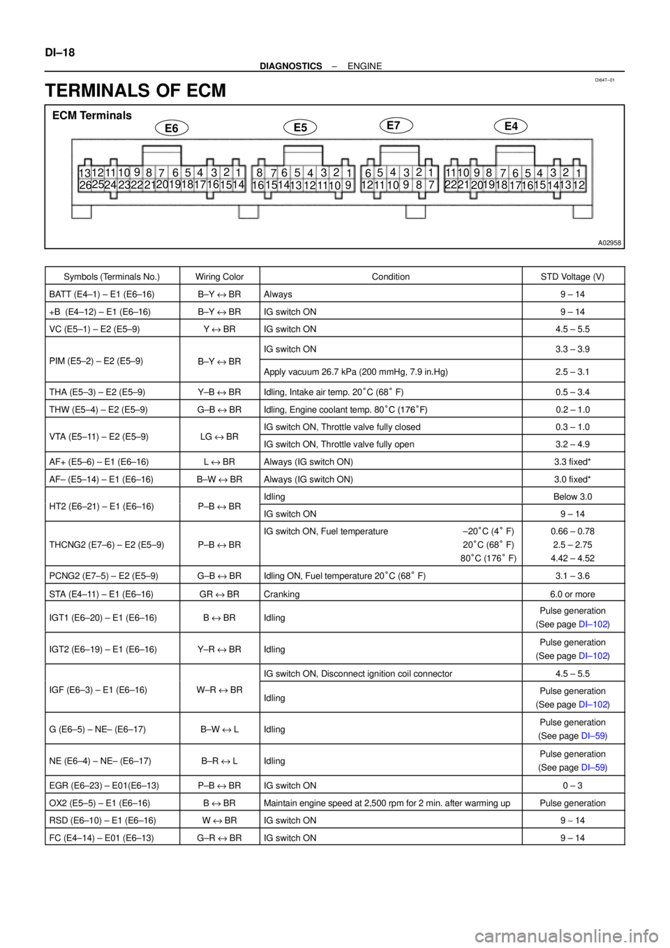
A02958
E4ECM Terminals
E6E5E7
11
19
1412 10 9 8
7652
43
18 21 22
20
16151
13
17 11 14
109
87 652 4
3
21 2220
16 15 131
12 11 1 09
652
43 1 12
7 8
19
14
109 8
7652
43
18
23 2416
151
17
11 12 13 25
26 DI±18
± DIAGNOSTICSENGINE
TERMINALS OF ECM
Symbols (Terminals No.)Wiring ColorConditionSTD Voltage (V)
BATT (E4±1) ± E1 (E6±16)B±Y e BRAlways9 ± 14
+B (E4±12) ± E1 (E6±16)B±Y e BRIG switch ON9 ± 14
VC (E5±1) ± E2 (E5±9)Ye BRIG switch ON4.5 ± 5.5
PIM (E5 2) E2 (E5 9)BYBR
IG switch ON3.3 ± 3.9
PIM (E5±2) ± E2 (E5±9)B±Y e BRApply vacuum 26.7 kPa (200 mmHg, 7.9 in.Hg)2.5 ± 3.1
THA (E5±3) ± E2 (E5±9)Y±B e BRIdling, Intake air temp. 20°C (68° F)0.5 ± 3.4
THW (E5±4) ± E2 (E5±9)G±B e BRIdling, Engine coolant temp. 80°C (176°F)0.2 ± 1.0
VTA (E5 11) E2 (E5 9)LGBRIG switch ON, Throttle valve fully closed0.3 ± 1.0VTA (E5±11) ± E2 (E5±9)LG e BRIG switch ON, Throttle valve fully open3.2 ± 4.9
AF+ (E5±6) ± E1 (E6±16)L e BRAlways (IG switch ON)3.3 fixed*
AF± (E5±14) ± E1 (E6±16)B±W e BRAlways (IG switch ON)3.0 fixed*
HT2 (E6 21) E1 (E6 16)PBBRIdlingBelow 3.0HT2 (E6±21) ± E1 (E6±16)P±B e BRIG switch ON9 ± 14
THCNG2 (E7±6) ± E2 (E5±9)P±B e BR
IG switch ON, Fuel temperature ±20°C (4° F)
20°C (68° F)
80°C (176° F)0.66 ± 0.78
2.5 ± 2.75
4.42 ± 4.52
PCNG2 (E7±5) ± E2 (E5±9)G±B e BRIdling ON, Fuel temperature 20°C (68° F)3.1 ± 3.6
STA (E4 11) E1 (E6 16)GRBRCki60STA (E4±11) ± E1 (E6±16)GR e BRCranking6.0 or more
IGT1 (E6±20) ± E1 (E6±16)B e BRIdlingPulse generation
(See page DI±102)
IGT2 (E6±19) ± E1 (E6±16)Y±R e BRIdlingPulse generation
(See page DI±102)
IG switch ON, Disconnect ignition coil connector4.5 ± 5.5
IGF (E6±3) ± E1 (E6±16)W±R e BRIdlingPulse generation
(See page DI±102)
G (E6±5) ± NE± (E6±17)B±W e LIdlingPulse generation
(See page DI±59)
NE (E6±4) ± NE± (E6±17)B±R e LIdlingPulse generation
(See page DI±59)
EGR (E6±23) ± E01(E6±13)P±B e BRIG switch ON0 ± 3
OX2 (E5±5) ± E1 (E6±16)B e BRMaintain engine speed at 2,500 rpm for 2 min. after warming upPulse generation
RSD (E6±10) ± E1 (E6±16)W e BRIG switch ON9 ~ 14
FC (E4±14) ± E01 (E6±13)G±R e BRIG switch ON9 ± 14
Page 2181 of 4592

A00310
Engine Coolant Temp.
Sensor
2
1ECM
G±B
BR4
E5
E595 V
THW
E2
E1 R DI±30
± DIAGNOSTICSENGINE
DTC P0115 Engine Coolant Temp. Circuit Malfunction
CIRCUIT DESCRIPTION
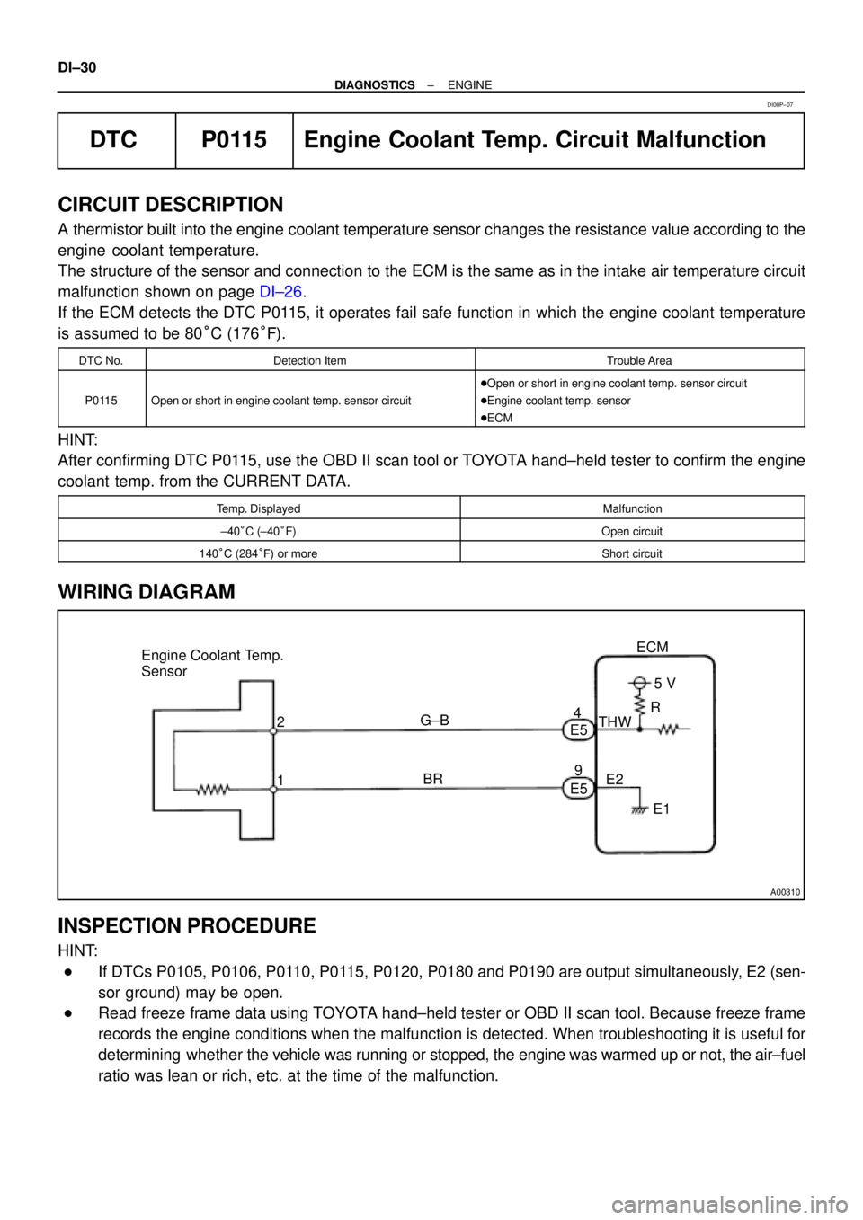
A thermistor built into the engine coolant temperature sensor changes the resistance value according to the
engine coolant temperature.
The structure of the sensor and connection to the ECM is the same as in the intake air temperature circuit
malfunction shown on page DI±26.
If the ECM detects the DTC P0115, it operates fail safe function in which the engine coolant temperature
is assumed to be 80°C (176°F).
DTC No.Detection ItemTrouble Area
P0115Open or short in engine coolant temp. sensor circuit
�Open or short in engine coolant temp. sensor circuit
�Engine coolant temp. sensor
�ECM
HINT:
After confirming DTC P0115, use the OBD II scan tool or TOYOTA hand±held tester to confirm the engine
coolant temp. from the CURRENT DATA.
Temp. DisplayedMalfunction
±40°C (±40°F)Open circuit
140°C (284°F) or moreShort circuit
WIRING DIAGRAM
INSPECTION PROCEDURE
HINT:
�If DTCs P0105, P0106, P0110, P0115, P0120, P0180 and P0190 are output simultaneously, E2 (sen-
sor ground) may be open.
�Read freeze frame data using TOYOTA hand±held tester or OBD II scan tool. Because freeze frame
records the engine conditions when the malfunction is detected. When troubleshooting it is useful for
determining whether the vehicle was running or stopped, the engine was warmed up or not, the air±fuel
ratio was lean or rich, etc. at the time of the malfunction.
DI00P±07
Page 2182 of 4592

A00395
ECM ON
Engine Coolant
Temp. Sensor
2
14
9
THW
E25 V
E1 E5
E5
± DIAGNOSTICSENGINE
DI±31
1 Connect OBD II scan tool or TOYOTA hand±held tester, and read value of engine
coolant temperature.
PREPARATION:
(a) Connect the OBD II scan tool or TOYOTA hand±held tester to the DLC3.
(b) Turn the ignition switch ON and push the OBD II scan tool or TOYOTA hand±held tester main switch
ON.
CHECK:
Read the temperature value on the OBD II scan tool or TOYOTA hand±held tester.
OK:
Same as actual engine coolant temperature.
HINT:
�If there is open circuit, OBD II scan tool or TOYOTA hand±held tester indicates ±40°C (±40°F).
�If there is open circuit, OBD II scan tool or TOYOTA hand-held tester indicates 140°C (284°F) or more.
NG ±40°C (±40°F) ... Go to step 2.
140°C (284°F) or more ... Go to step 4.
OK
Check for intermittent problems (See page
DI±3).
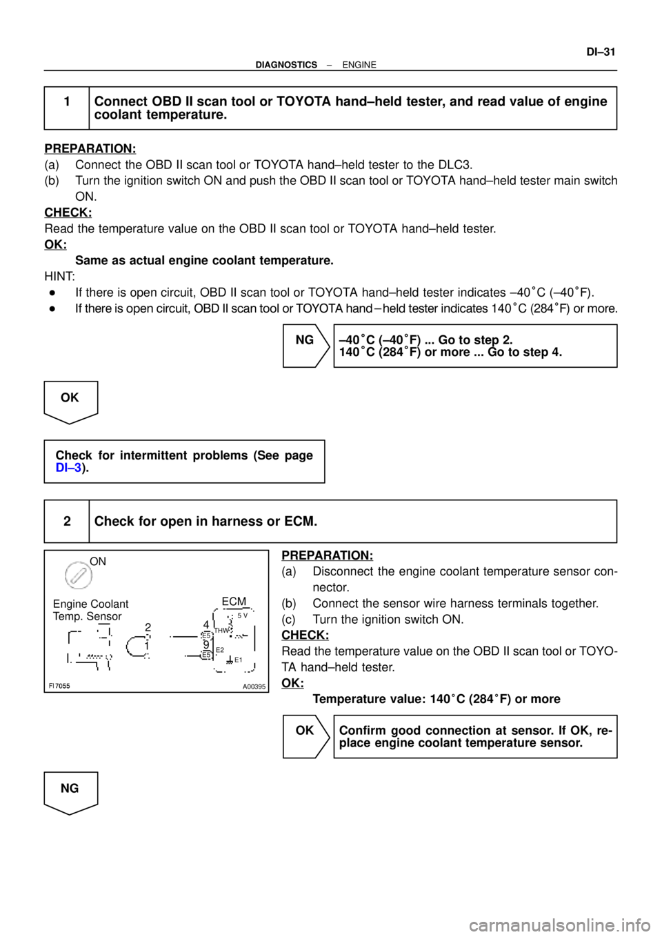
2 Check for open in harness or ECM.
PREPARATION:
(a) Disconnect the engine coolant temperature sensor con-
nector.
(b) Connect the sensor wire harness terminals together.
(c) Turn the ignition switch ON.
CHECK:
Read the temperature value on the OBD II scan tool or TOYO-
TA hand±held tester.
OK:
Temperature value: 140°C (284°F) or more
OK Confirm good connection at sensor. If OK, re-
place engine coolant temperature sensor.
NG
Page 2183 of 4592

A03012A09258
ON
Engine Coolant
Temp. SensorECM
THW
E2
4
2
15 V
THW
E1 E5
E5
9E2
A00397
ON
Engine Coolant
Temp. Sensor
4
9ECM
E5
E5THW
E25 V
E1
DI±32
± DIAGNOSTICSENGINE
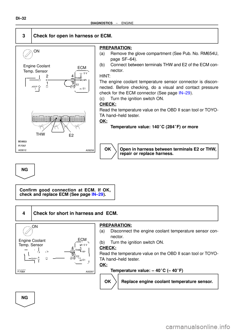
3 Check for open in harness or ECM.
PREPARATION:
(a) Remove the glove compartment (See Pub. No. RM654U,
page SF±64).
(b) Connect between terminals THW and E2 of the ECM con-
nector.
HINT:
The engine coolant temperature sensor connector is discon-
nected. Before checking, do a visual and contact pressure
check for the ECM connector (See page IN±29).
(c) Turn the ignition switch ON.
CHECK:
Read the temperature value on the OBD II scan tool or TOYO-
TA hand±held tester.
OK:
Temperature value: 140°C (284°F) or more
OK Open in harness between terminals E2 or THW,
repair or replace harness.
NG
Confirm good connection at ECM. If OK,
check and replace ECM (See page IN±29).
4 Check for short in harness and ECM.
PREPARATION:
(a) Disconnect the engine coolant temperature sensor con-
nector.
(b) Turn the ignition switch ON.
CHECK:
Read the temperature value on the OBD II scan tool or TOYO-
TA hand±held tester.
OK:
Temperature value: ± 40°C (± 40°F)
OK Replace engine coolant temperature sensor.
NG
Page 2184 of 4592
A03011A09257
Engine Coolant
Temp. Sensor
THW
E25 V
E1
ON
E5 Connector
± DIAGNOSTICSENGINE
DI±33
5 Check for short in harness or ECM.
PREPARATION:
(a) Remove the glove compartment (See Pub. No. RM654U,
page SF±64).
(b) Disconnect the E5 connector from the ECM.
HINT:
The engine coolant temp. sensor connector is disconnected.
(c) Turn the ignition switch ON.
CHECK:
Read the temperature value on the OBD II scan tool or TOYO-
TA hand±held tester.
OK:
Temperature value: ±40°C (±40°F)
OK Repair or replace harness or connector.
NG
Check and replace ECM (See page IN±29).
Page 2185 of 4592

DI±34
± DIAGNOSTICSENGINE
DTC P0116 Engine Coolant Temp. Circuit Range/Perfor-
mance Problem
CIRCUIT DESCRIPTION
Refer to DTC P0115 on page DI±30.
DTC No.DTC Detecting ConditionTrouble Area
If THW < ±7°C (19.4°F) or THA < ±7°C (19.4°F) 20 min. or
more after starting engine, engine coolant temp. sensor value
is ±10°C (±50°F)* or less (2 trip detection logic)
P0116
When THW 35°C (95°F) and 60°C (140°F), THA �
±6.7°C (19.9°F) when starting the engine, conditions (a) and
(b) continue: (2 trip detection logic)
(a) Vehicle speed is changing (Not stable)
(b) Water temperature change is lower than 3°C (37.4°F) from
water temperature since when starting the engine�Cooling system
�Engine coolant temp. sensor
INSPECTION PROCEDURE
HINT:
�If DTCs P0105, P0106, P0110, P0115, P0120, P0180 and P0190 are output simultaneously, engine
coolant temperature sensor circuit may be open. Perform troubleshooting of DTC P0115 first.
�Read freeze frame data using TOYOTA hand±held tester or OBD II scan tool. Because freeze frame
records the engine conditions when the malfunction is detected. When troubleshooting it is useful for
determining whether the vehicle was running or stopped, the engine was warmed up or not, the air±fuel
ratio was lean or rich, etc. at the time of the malfunction.
1 Are there any other codes (besides DTC P0116) being output?
YES Go to relevant DTC chart.
NO
2 Check thermostat (See Pub. No. RM654U, page CO±10).
NG Replace thermostat.
OK
Replace engine coolant temperature sensor.
DI00Q±07
Page 2191 of 4592

A00477
Atmosphere
Cover
Exhaust GasPlatinum
Electrode
Solid Electrolyte
(Zirconia Element)
Platinum
Electrode
Heater
Air±Fuel Ratio
(V)
2.6 4.0
3.8
3.6
3.4
3.2
3.0
2.8
2.4
14 15 16 17 19 21 22
Coating (Ceramic)
ECM Monitored
A/F Sensor Voltage
DI±40
± DIAGNOSTICSENGINE
DTC P0125 Insufficient Coolant Temp. for Closed Loop
Fuel Control
CIRCUIT DESCRIPTION
To obtain a high purification rate for the CO, HC and NOx components of the exhaust gas, a three±way cata-
lytic converter is used, but for the most efficient use of the three±way catalytic converter, the air±fuel ratio
must be precisely controlled so that it is always close to the stoichiometric air±fuel ratio.
The A/F sensor has the characteristic that provides output voltage
* approximately proportional to the exist-
ing air±fuel ratio. The A/F sensor output voltage
* is used to provide feedback for the ECM to control the air±
fuel ratio.
By the A/F sensor output, the ECM can determine the deviation amount from the stoichiometric air±fuel ratio
and control the proper injection time immediately. If the A/F sensor is malfunctioning, ECM is unable to per-
form accurate air±fuel ratio control.
The A/F sensor is equipped with a heater which heats the zirconia element. The heater is controlled by the
ECM. When the intake air volume is low (the temp. of the exhaust gas is low), current flows to the heater
to heat the sensor for accurate oxygen concentration detection.
*: The voltage value changes at the inside of the ECM only.
DTC No.DTC Detecting ConditionTrouble Area
P0125
After engine is warmed up, A/F sensor output* does not
change when conditions (a), (b) and (c) continue for at least
1.5 min.:
*: Output value changes at inside of ECM only
(a) Engine speed: 1,500 rpm or more
(b) Vehicle speed: 40 ± 100 km/h (25 ± 62 mph)
(c) Throttle valve is not fully closed�Open or short in A/F sensor (bank 1 sensor 1) circuit
�A/F sensor (bank 1 sensor 1)
�Air induction system
�EGR system
�Fuel pressure
�Injector
�Gas leakage on exhaust system
�ECM
HINT:
�After confirming DTC P0125, use the OBD II scan tool or TOYOTA hand-held tester to confirm voltage
output of A/F sensor from the CURRENT DATA.
�The ECM controls the voltage of the AF+ and AF± terminals of the ECM to the fixed voltage. Therefore,
it is impossible to confirm the A/F sensor output voltage without OBD II scan tool or TOYOTA hand±
held tester.
DI1JU±04