Page 1490 of 4592

DI±278
± DIAGNOSTICSENGINE (1MZ±FE)
513 Author�: Date�:
INSPECTION PROCEDURE
HINT:
�If is the case that DTC besides misfire is memorized simultaneously, first perform the troubleshooting
for them.
�Read freeze frame data using TOYOTA hand±held tester or OBD II scan tool. Because freeze frame
data records the engine conditions when the malfunction is detected, when troubleshooting it is useful
for determining whether the vehicle was running or stopped, the engine warmed up or not, the air±fuel
ratio lean or rich, etc. at the time of the malfunction.
�When the vehicle is brought to the workshop and the misfire is not occurred, misfire can be confirmed
by reproducing the condition or freeze frame data. Also, after finishing the repair, confirm that there
is no misfire. (See the confirmation driving pattern)
�When either of SHORT FT #1, LONG FT #1, SHORT FT #2 or LONG FT #2 in the freeze frame data
is besides the range of ±20%, there is a possibility that the air±fuel ratio is inclining either to ºrichº
(±20% or less) or ºleanº (+20% or more).
�When COOLANT TEMP in the freeze frame data is less than 80°C (176°F), there is a possibility or
misfire only during warming up.
�In the case that misfire cannot be reproduced, the reason may be because of the driving with lack or
fuel, the use of improper fuel, a stain of ignition plug, and etc.
1 Check wire harness, connector and vacuum hose in engine room.
CHECK:
(a) Check the connection conditions of wire harness and connector.
(b) Check the disconnection, piping and break of vacuum hose.
NG Repair or replace, then confirm that there is no
misfire (See the confirmation driving pattern).
OK
Page 1494 of 4592
DI±282
± DIAGNOSTICSENGINE (1MZ±FE)
517 Author�: Date�:
8 Check mass air flow meter and engine coolant temp. sensor
(See pages SF±35, SF±63).
NG Repair or replace.
OK
Check compression pressure, valve
clearance and valve timing.
Page 1504 of 4592

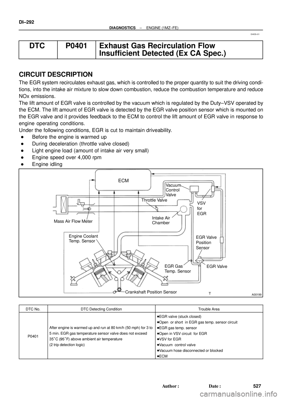
A00199
ECM
Mass Air Flow MeterVSV
for
EGR
EGR Valve
Position
Sensor
EGR Valve EGR Gas
Temp. Sensor
Crankshaft Position Sensor Engine Coolant
Temp. SensorIntake Air
Chamber Throttle ValveVacuum
Control
Valve
DI±292
± DIAGNOSTICSENGINE (1MZ±FE)
527 Author�: Date�:
DTC P0401 Exhaust Gas Recirculation Flow
Insufficient Detected (Ex CA Spec.)
CIRCUIT DESCRIPTION
The EGR system recirculates exhaust gas, which is controlled to the proper quantity to suit the driving condi-
tions, into the intake air mixture to slow down combustion, reduce the combustion temperature and reduce
NOx emissions.
The lift amount of EGR valve is controlled by the vacuum which is regulated by the Duty±VSV operated by
the ECM. The lift amount of EGR valve is detected by the EGR valve position sensor which is mounted on
the EGR valve and it provides feedback to the ECM to control the lift amount of EGR valve in response to
engine operating conditions.
Under the following conditions, EGR is cut to maintain driveability.
�Before the engine is warmed up
�During deceleration (throttle valve closed)
�Light engine load (amount of intake air very small)
�Engine speed over 4,000 rpm
�Engine idling
DTC No.DTC Detecting ConditionTrouble Area
P0401
After engine is warmed up and run at 80 km/h (50 mph) for 3 to
5 min. EGR gas temperature sensor valve does not exceed
35°C (95°F) above ambient air temperature
(2 trip detection logic)
�EGR valve (stuck closed)
�Open or short in EGR gas temp. sensor circuit
�EGR gas temp. sensor
�Open in VSV circuit for EGR
�VSV for EGR
�Vacuum control valve
�Vacuum hose disconnected or blocked
�ECM
DI4DS±01
Page 1552 of 4592

DI±340
± DIAGNOSTICSENGINE (1MZ±FE)
575 Author�: Date�:
DTC P1130 A/F Sensor Circuit Range/Performance Mal-
function (Only for California Spec.)
DTC P1150 A/F Sensor Circuit Range/Performance Mal-
function (Only for California Spec.)
CIRCUIT DESCRIPTION
Refer to DTC P0125 (Insufficient Temp. for Closed Loop Fuel Control (Only for California Spec.)) on Page
DI±249.
DTC No.DTC Detecting ConditionTrouble Area
Voltage output* of A/F sensor remains at 3.8 V or more, or
2.8 V or less, during engine running after engine is warmed
up (2 trip detection logic)
*: Output value changes at inside of ECM only.
P1130
P1150Voltage output* of A/F sensor does not change from 3.30 V,
during engine running after engine is warmed up
(2 trip detection logic)
*: Output value changes at inside of ECM only.�Open or short in A/F sensor (bank 1, 2 sensor 1) circuit
�A/F sensor (bank 1, 2 sensor 1)
�ECM
Open or short in A/F sensor circuit
(2 trip detection logic)
HINT:
�After confirming DTC P1130 or P01150, use the OBD II scan tool or TOYOTA hand±held tester to con-
firm voltage output of A/F sensor (AFS B1 S1/O2S B1 S1) from ºCURRENT DATAº.
�The A/F sensor's output voltage and the short±term fuel value can be read using the OBD II scan tool
or TOYOTA hand±held tester.
�The ECM controls the voltage of AFR/AFL� and AFR/AFL� terminals of ECM to the fixed voltage.
Therefore, it is impossible to confirm the A/F sensor output voltage without OBD II scan tool or TOYOTA
hand±held tester.
�OBD II scan tool (excluding TOYOTA hand±held tester) displays the one fifth of the A/F sensor output
voltage which is displayed on the TOYOTA hand±held tester.
WIRING DIAGRAM
Refer to DTC P0125 (Insufficient Coolant Temp. for Closed Loop Fuel Control (Only for California Spec.))
on page DI±249.
DI1K6±03
Page 1557 of 4592

± DIAGNOSTICSENGINE (1MZ±FE)
DI±345
580 Author�: Date�:
DTC P1133 A/F Sensor Circuit Response Malfunction
(Bank 1 Sensor 1) (Only for California Spec.)
DTC P1153 A/F Sensor Circuit Response Malfunction
(Bank 2 Sensor 1) (Only for California Spec.)
CIRCUIT DESCRIPTION
Refer to DTC P0125 (Insufficient Coolant Temp. for Closed Loop Fuel Control (Only for California Spec.))
on page DI±249.
DTC No.DTC Detecting ConditionTrouble Area
P1133
P1155
After engine is warmed up and during vehicle driving at
engine speed 1,400 rpm or more and vehicle speed 60
km/h (38 mph) or more, if response characteristic of A/F
sensor becomes deteriorated
(2 trip detection logic)
�A/F sensors (bank 1, 2 sensor 1)
INSPECTION PROCEDURE
HINT:
Read freeze frame data using TOYOTA hand±held tester or OBD II scan tool. Because freeze frame records
the engine conditions when the malfunction is detected, when troubleshooting it is useful for determining
whether the vehicle was running or stopped, the engine warmed up or not, the air±fuel ratio lean or rich, etc.
at the time of the malfunction.
1 Are there any other codes (besides DTC P1133, P1153) being output?
YES Go to relevant DTC chart.
NO
DI1K7±03
Page 1561 of 4592

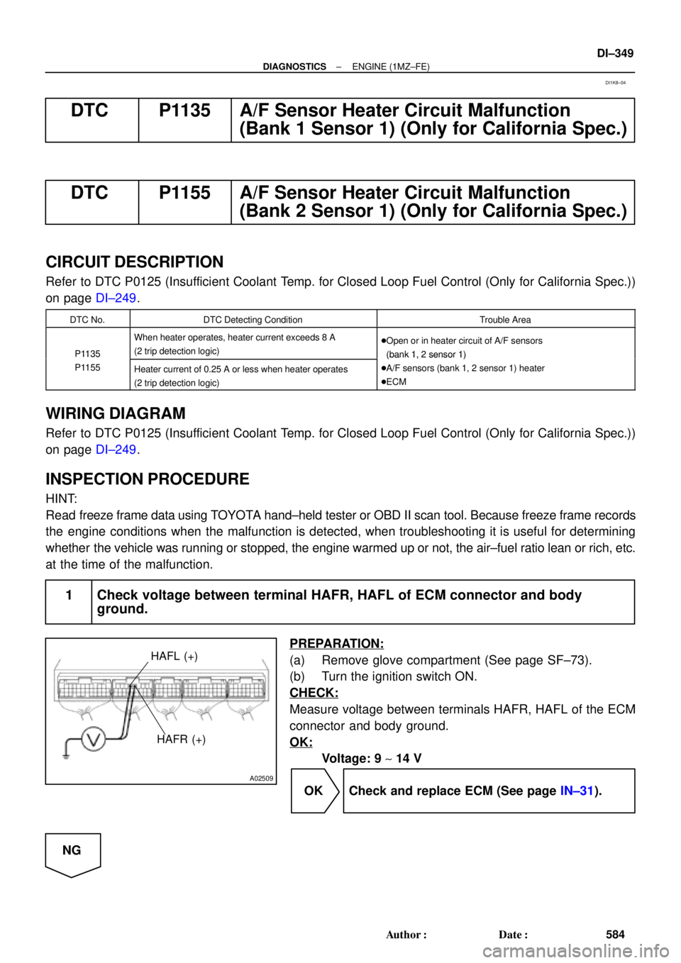
A02509
HAFL (+)
HAFR (+)
± DIAGNOSTICSENGINE (1MZ±FE)
DI±349
584 Author�: Date�:
DTC P1135 A/F Sensor Heater Circuit Malfunction
(Bank 1 Sensor 1) (Only for California Spec.)
DTC P1155 A/F Sensor Heater Circuit Malfunction
(Bank 2 Sensor 1) (Only for California Spec.)
CIRCUIT DESCRIPTION
Refer to DTC P0125 (Insufficient Coolant Temp. for Closed Loop Fuel Control (Only for California Spec.))
on page DI±249.
DTC No.DTC Detecting ConditionTrouble Area
P1135
When heater operates, heater current exceeds 8 A
(2 trip detection logic)�Open or in heater circuit of A/F sensors
(bank 1, 2 sensor 1)P1135
P1155Heater current of 0.25 A or less when heater operates
(2 trip detection logic)
(bank 1, 2 sensor 1)
�A/F sensors (bank 1, 2 sensor 1) heater
�ECM
WIRING DIAGRAM
Refer to DTC P0125 (Insufficient Coolant Temp. for Closed Loop Fuel Control (Only for California Spec.))
on page DI±249.
INSPECTION PROCEDURE
HINT:
Read freeze frame data using TOYOTA hand±held tester or OBD II scan tool. Because freeze frame records
the engine conditions when the malfunction is detected, when troubleshooting it is useful for determining
whether the vehicle was running or stopped, the engine warmed up or not, the air±fuel ratio lean or rich, etc.
at the time of the malfunction.
1 Check voltage between terminal HAFR, HAFL of ECM connector and body
ground.
PREPARATION:
(a) Remove glove compartment (See page SF±73).
(b) Turn the ignition switch ON.
CHECK:
Measure voltage between terminals HAFR, HAFL of the ECM
connector and body ground.
OK:
Voltage: 9 ~ 14 V
OK Check and replace ECM (See page IN±31).
NG
DI1K8±04
Page 1571 of 4592

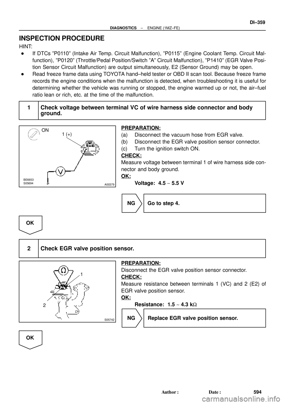
A00379
ON
1 (+)
BE6653S05694
S05742
1
2
± DIAGNOSTICSENGINE (1MZ±FE)
DI±359
594 Author�: Date�:
INSPECTION PROCEDURE
HINT:
�If DTCs ºP0110º (Intake Air Temp. Circuit Malfunction), ºP0115º (Engine Coolant Temp. Circuit Mal-
function), ºP0120º (Throttle/Pedal Position/Switch ºAº Circuit Malfunction), ºP1410º (EGR Valve Posi-
tion Sensor Circuit Malfunction) are output simultaneously, E2 (Sensor Ground) may be open.
�Read freeze frame data using TOYOTA hand±held tester or OBD II scan tool. Because freeze frame
records the engine conditions when the malfunction is detected, when troubleshooting it is useful for
determining whether the vehicle was running or stopped, the engine warmed up or not, the air±fuel
ratio lean or rich, etc. at the time of the malfunction.
1 Check voltage between terminal VC of wire harness side connector and body
ground.
PREPARATION:
(a) Disconnect the vacuum hose from EGR valve.
(b) Disconnect the EGR valve position sensor connector.
(c) Turn the ignition switch ON.
CHECK:
Measure voltage between terminal 1 of wire harness side con-
nector and body ground.
OK:
Voltage: 4.5 ~ 5.5 V
NG Go to step 4.
OK
2 Check EGR valve position sensor.
PREPARATION:
Disconnect the EGR valve position sensor connector.
CHECK:
Measure resistance between terminals 1 (VC) and 2 (E2) of
EGR valve position sensor.
OK:
Resistance: 1.5 ~ 4.3 kW
NG Replace EGR valve position sensor.
OK
Page 1574 of 4592
DI±362
± DIAGNOSTICSENGINE (1MZ±FE)
597 Author�: Date�:
DTC P1411 EGR Valve Position Sensor Circuit
Range/Performance Problem
CIRCUIT DESCRIPTION
Refer to DTC P1410 (EGR Valve Position Sensor Circuit Malfunction) on page DI±358.
DTC No.DTC Detecting ConditionTrouble Area
P1411
Conditions (a) and (b) continue for 500 msec. or more:
(2 trip detection logic)
(a) Engine Coolant Temp. < 55C (415F)
(b) EGLS � 1.65 V or EGLS < 0.35 V
�EGR valve position sensor
INSPECTION PROCEDURE
HINT:
Read freeze frame data using TOYOTA hand±held tester or OBD II scan tool. Because freeze frame records
the engine conditions when the malfunction is detected, when troubleshooting it is useful for determining
whether the vehicle was running or stopped, the engine warmed up or not, the air±fuel ratio lean or rich, etc.
at the time of the malfunction.
1 Are there any other codes (besides DTC P1411) being output?
YES Go to relevant DTC chart.
NO
Replace EGR valve position sensor.
DI087±06