Page 1226 of 1456
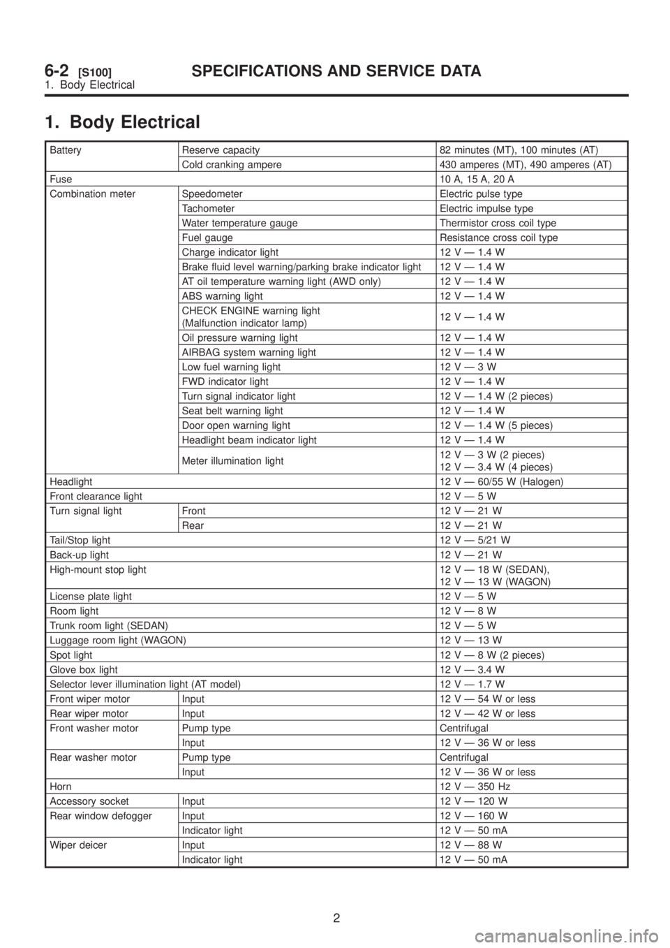
1. Body Electrical
Battery Reserve capacity 82 minutes (MT), 100 minutes (AT)
Cold cranking ampere 430 amperes (MT), 490 amperes (AT)
Fuse10 A, 15 A, 20 A
Combination meter Speedometer Electric pulse type
Tachometer Electric impulse type
Water temperature gauge Thermistor cross coil type
Fuel gauge Resistance cross coil type
Charge indicator light 12 V Ð 1.4 W
Brake fluid level warning/parking brake indicator light 12 V Ð 1.4 W
AT oil temperature warning light (AWD only) 12 V Ð 1.4 W
ABS warning light 12 V Ð 1.4 W
CHECK ENGINE warning light
(Malfunction indicator lamp)12 V Ð 1.4 W
Oil pressure warning light 12 V Ð 1.4 W
AIRBAG system warning light 12 V Ð 1.4 W
Low fuel warning light 12VÐ3W
FWD indicator light 12 V Ð 1.4 W
Turn signal indicator light 12 V Ð 1.4 W (2 pieces)
Seat belt warning light 12 V Ð 1.4 W
Door open warning light 12 V Ð 1.4 W (5 pieces)
Headlight beam indicator light 12 V Ð 1.4 W
Meter illumination light12VÐ3W(2pieces)
12 V Ð 3.4 W (4 pieces)
Headlight12 V Ð 60/55 W (Halogen)
Front clearance light 12VÐ5W
Turn signal light Front 12VÐ21W
Rear 12VÐ21W
Tail/Stop light12 V Ð 5/21 W
Back-up light12VÐ21W
High-mount stop light 12VÐ18W(SEDAN),
12VÐ13W(WAGON)
License plate light 12VÐ5W
Room light12VÐ8W
Trunk room light (SEDAN) 12VÐ5W
Luggage room light (WAGON) 12VÐ13W
Spot light12VÐ8W(2pieces)
Glove box light 12 V Ð 3.4 W
Selector lever illumination light (AT model) 12 V Ð 1.7 W
Front wiper motor Input 12VÐ54Worless
Rear wiper motor Input 12VÐ42Worless
Front washer motor Pump type Centrifugal
Input 12VÐ36Worless
Rear washer motor Pump type Centrifugal
Input 12VÐ36Worless
Horn12 V Ð 350 Hz
Accessory socket Input 12 V Ð 120 W
Rear window defogger Input 12 V Ð 160 W
Indicator light 12VÐ50mA
Wiper deicer Input 12VÐ88W
Indicator light 12VÐ50mA
2
6-2[S100]SPECIFICATIONS AND SERVICE DATA
1. Body Electrical
Page 1237 of 1456
6. Stop and Tail Light
A: REMOVAL AND INSTALLATION
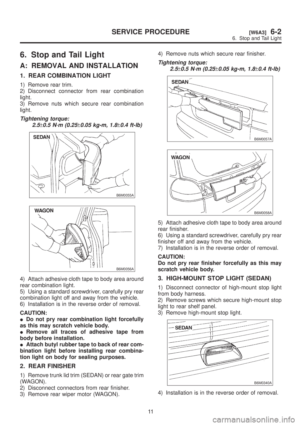
1. REAR COMBINATION LIGHT
1) Remove rear trim.
2) Disconnect connector from rear combination
light.
3) Remove nuts which secure rear combination
light.
Tightening torque:
2.5
±0.5 N´m (0.25±0.05 kg-m, 1.8±0.4 ft-lb)
B6M0055A
B6M0056A
4) Attach adhesive cloth tape to body area around
rear combination light.
5) Using a standard screwdriver, carefully pry rear
combination light off and away from the vehicle.
6) Installation is in the reverse order of removal.
CAUTION:
IDo not pry rear combination light forcefully
as this may scratch vehicle body.
IRemove all traces of adhesive tape from
body before installation.
IAttach butyl rubber tape to back of rear com-
bination light before installing rear combina-
tion light on body for sealing purposes.
2. REAR FINISHER
1) Remove trunk lid trim (SEDAN) or rear gate trim
(WAGON).
2) Disconnect connectors from rear finisher.
3) Remove rear wiper motor (WAGON).4) Remove nuts which secure rear finisher.
Tightening torque:
2.5
±0.5 N´m (0.25±0.05 kg-m, 1.8±0.4 ft-lb)
B6M0057A
B6M0058A
5) Attach adhesive cloth tape to body area around
rear finisher.
6) Using a standard screwdriver, carefully pry rear
finisher off and away from the vehicle.
7) Installation is in the reverse order of removal.
CAUTION:
Do not pry rear finisher forcefully as this may
scratch vehicle body.
3. HIGH-MOUNT STOP LIGHT (SEDAN)
1) Disconnect connector of high-mount stop light
from body harness.
2) Remove screws which secure high-mount stop
light to rear shelf panel.
3) Remove high-mount stop light.
B6M0340A
4) Installation is in the reverse order of removal.
11
[W6A3]6-2SERVICE PROCEDURE
6. Stop and Tail Light
Page 1238 of 1456
4. HIGH-MOUNT STOP LIGHT (WAGON)
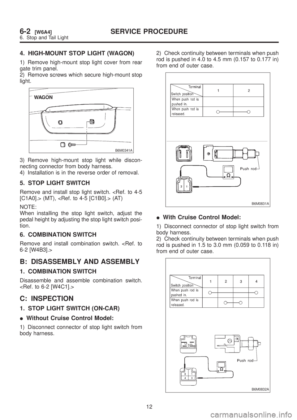
1) Remove high-mount stop light cover from rear
gate trim panel.
2) Remove screws which secure high-mount stop
light.
B6M0341A
3) Remove high-mount stop light while discon-
necting connector from body harness.
4) Installation is in the reverse order of removal.
5. STOP LIGHT SWITCH
Remove and install stop light switch.
[C1A0].> (MT), (AT)
NOTE:
When installing the stop light switch, adjust the
pedal height by adjusting the stop light switch posi-
tion.
6. COMBINATION SWITCH
Remove and install combination switch.
6-2 [W4B3].>
B: DISASSEMBLY AND ASSEMBLY
1. COMBINATION SWITCH
Disassemble and assemble combination switch.
C: INSPECTION
1. STOP LIGHT SWITCH (ON-CAR)
IWithout Cruise Control Model:
1) Disconnect connector of stop light switch from
body harness.2) Check continuity between terminals when push
rod is pushed in 4.0 to 4.5 mm (0.157 to 0.177 in)
from end of outer case.
B6M0831A
IWith Cruise Control Model:
1) Disconnect connector of stop light switch from
body harness.
2) Check continuity between terminals when push
rod is pushed in 1.5 to 3.0 mm (0.059 to 0.118 in)
from end of outer case.
B6M0832A
12
6-2[W6A4]SERVICE PROCEDURE
6. Stop and Tail Light
Page 1240 of 1456
![SUBARU LEGACY 1999 Service Repair Manual 7. Turn Signal and Hazard
Warning Light
A: REMOVAL AND INSTALLATION
1. FRONT TURN SIGNAL LIGHT
Remove and install front turn signal light. <Ref. to
6-2 [W4B2].>
NOTE:
The front turn signal light is un SUBARU LEGACY 1999 Service Repair Manual 7. Turn Signal and Hazard
Warning Light
A: REMOVAL AND INSTALLATION
1. FRONT TURN SIGNAL LIGHT
Remove and install front turn signal light. <Ref. to
6-2 [W4B2].>
NOTE:
The front turn signal light is un](/manual-img/17/57435/w960_57435-1239.png)
7. Turn Signal and Hazard
Warning Light
A: REMOVAL AND INSTALLATION
1. FRONT TURN SIGNAL LIGHT
Remove and install front turn signal light.
6-2 [W4B2].>
NOTE:
The front turn signal light is united with headlight
assembly.
2. REAR COMBINATION LIGHT
Remove and install rear combination light.
6-2 [W6A1].>
3. COMBINATION SWITCH
Remove and install combination switch.
6-2 [W4B3].>
4. HAZARD SWITCH
1) Remove center panel from instrument panel.
2) Disconnect connector of hazard switch from
body harness.
3) Remove hazard switch from center panel.
B6M0063
4) Installation is in the reverse order of removal.
5. TURN SIGNAL AND HAZARD UNIT
1) Remove instrument panel lower cover.
2) Remove engine hood opener lever bracket.
3) Disconnect connector of turn signal and hazard
unit.4) Remove screw, and then remove turn signal
and hazard unit from bracket.
B6M0343A
5) Installation is in the reverse order of removal.
B: DISASSEMBLY AND ASSEMBLY
1. COMBINATION SWITCH
Disassemble and assemble combination switch.
C: INSPECTION
1. COMBINATION SWITCH (ON-CAR)
1) Remove instrument panel lower cover.
2) Remove lower column cover.
3) Unfasten holddown clip which secures harness,
and disconnect connectors from body harness.
4) Move combination switch to respective posi-
tions and check continuity between terminals.
B6M0702
14
6-2[W7A1]SERVICE PROCEDURE
7. Turn Signal and Hazard Warning Light
Page 1241 of 1456
B6M0238
2. HAZARD SWITCH
Move hazard switch to each position and check
continuity between terminals.
B6M0834A
8. Back-up Light
A: REMOVAL AND INSTALLATION
1. BACK-UP LIGHT
Remove and install rear finisher.
[W6A2].>
2. BACK-UP LIGHT SWITCH (MT MODEL)
Remove and install back-up light switch.
3-1 [W2B1].> (AWD), (FWD)
3. INHIBITOR SWITCH (AT MODEL)
Remove and install inhibitor switch (R position
switch).
B: INSPECTION
1. INHIBITOR SWITCH (AT MODEL)
Inspect inhibitor switch.
15
[W8B1]6-2SERVICE PROCEDURE
8. Back-up Light
Page 1242 of 1456
B6M0238
2. HAZARD SWITCH
Move hazard switch to each position and check
continuity between terminals.
B6M0834A
8. Back-up Light
A: REMOVAL AND INSTALLATION
1. BACK-UP LIGHT
Remove and install rear finisher.
[W6A2].>
2. BACK-UP LIGHT SWITCH (MT MODEL)
Remove and install back-up light switch.
3-1 [W2B1].> (AWD), (FWD)
3. INHIBITOR SWITCH (AT MODEL)
Remove and install inhibitor switch (R position
switch).
B: INSPECTION
1. INHIBITOR SWITCH (AT MODEL)
Inspect inhibitor switch.
15
[W8B1]6-2SERVICE PROCEDURE
8. Back-up Light
Page 1243 of 1456
9. Room Light and Door Switch
A: REMOVAL AND INSTALLATION
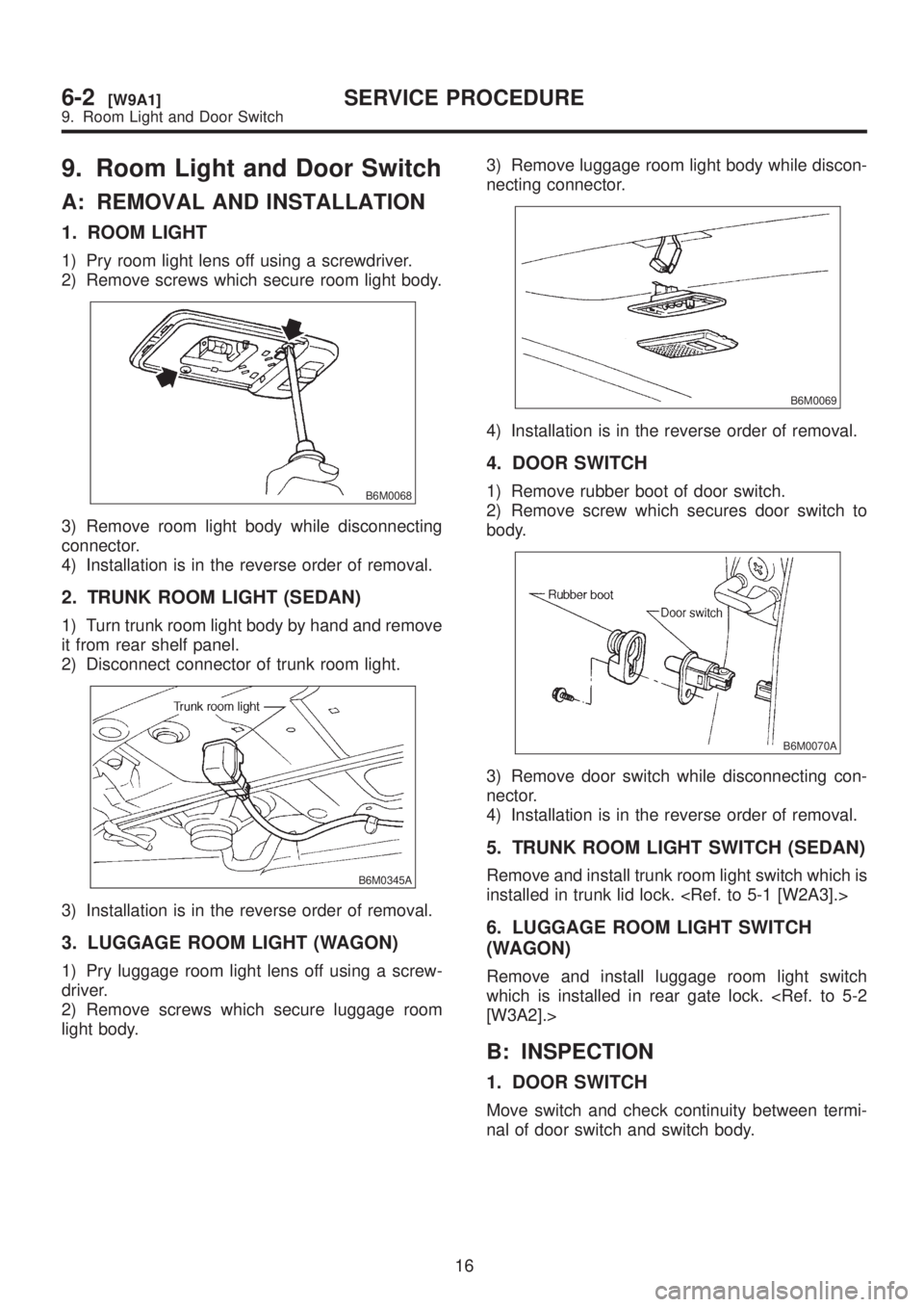
1. ROOM LIGHT
1) Pry room light lens off using a screwdriver.
2) Remove screws which secure room light body.
B6M0068
3) Remove room light body while disconnecting
connector.
4) Installation is in the reverse order of removal.
2. TRUNK ROOM LIGHT (SEDAN)
1) Turn trunk room light body by hand and remove
it from rear shelf panel.
2) Disconnect connector of trunk room light.
B6M0345A
3) Installation is in the reverse order of removal.
3. LUGGAGE ROOM LIGHT (WAGON)
1) Pry luggage room light lens off using a screw-
driver.
2) Remove screws which secure luggage room
light body.3) Remove luggage room light body while discon-
necting connector.
B6M0069
4) Installation is in the reverse order of removal.
4. DOOR SWITCH
1) Remove rubber boot of door switch.
2) Remove screw which secures door switch to
body.
B6M0070A
3) Remove door switch while disconnecting con-
nector.
4) Installation is in the reverse order of removal.
5. TRUNK ROOM LIGHT SWITCH (SEDAN)
Remove and install trunk room light switch which is
installed in trunk lid lock.
6. LUGGAGE ROOM LIGHT SWITCH
(WAGON)
Remove and install luggage room light switch
which is installed in rear gate lock.
[W3A2].>
B: INSPECTION
1. DOOR SWITCH
Move switch and check continuity between termi-
nal of door switch and switch body.
16
6-2[W9A1]SERVICE PROCEDURE
9. Room Light and Door Switch
Page 1250 of 1456
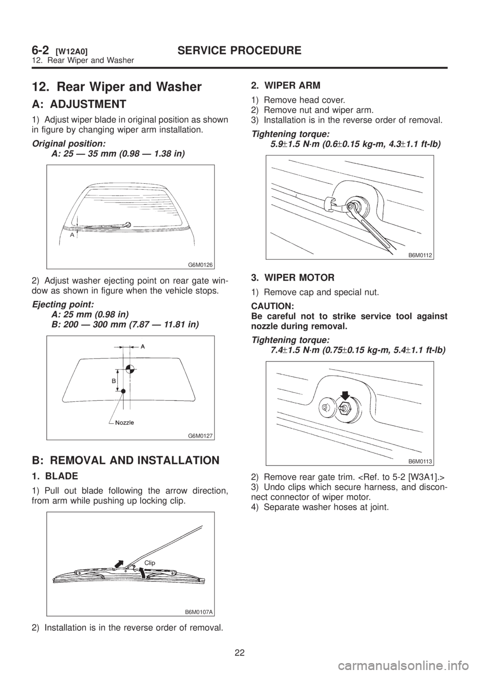
12. Rear Wiper and Washer
A: ADJUSTMENT
1) Adjust wiper blade in original position as shown
in figure by changing wiper arm installation.
Original position:
A: 25 Ð 35 mm (0.98 Ð 1.38 in)
G6M0126
2) Adjust washer ejecting point on rear gate win-
dow as shown in figure when the vehicle stops.
Ejecting point:
A: 25 mm (0.98 in)
B: 200 Ð 300 mm (7.87 Ð 11.81 in)
G6M0127
B: REMOVAL AND INSTALLATION
1. BLADE
1) Pull out blade following the arrow direction,
from arm while pushing up locking clip.
B6M0107A
2) Installation is in the reverse order of removal.
2. WIPER ARM
1) Remove head cover.
2) Remove nut and wiper arm.
3) Installation is in the reverse order of removal.
Tightening torque:
5.9
±1.5 N´m (0.6±0.15 kg-m, 4.3±1.1 ft-lb)
B6M0112
3. WIPER MOTOR
1) Remove cap and special nut.
CAUTION:
Be careful not to strike service tool against
nozzle during removal.
Tightening torque:
7.4
±1.5 N´m (0.75±0.15 kg-m, 5.4±1.1 ft-lb)
B6M0113
2) Remove rear gate trim.
3) Undo clips which secure harness, and discon-
nect connector of wiper motor.
4) Separate washer hoses at joint.
22
6-2[W12A0]SERVICE PROCEDURE
12. Rear Wiper and Washer