Page 1187 of 1456
2. Generator
B6M0414B
(1) Pulley nut
(2) Pulley
(3) Front cover ASSY
(4) Ball bearing
(5) Bearing retainer
(6) Screw
(7) Rotor
(8) Stator coil
(9) IC regulator ASSY(10) Condenser
(11) Diode ASSY
(12) Bolt
(13) Bolt
(14) Brush holder ASSY
(15) Rear cover
(16) BAT. terminal
(17) Nut
(18) Bolt(19) Through bolt
Tightening torque: N´m (kg-m, ft-lb)
T1:
3.1 Ð 4.4 (0.32 Ð 0.45, 2.3 Ð
3.3)
T2:63.7 Ð 83.4 (6.5 Ð 8.5, 47.0
Ð 61.5)
6
6-1[C200]COMPONENT PARTS
2. Generator
Page 1196 of 1456
2. Generator
A: REMOVAL AND INSTALLATION
1) Disconnect battery ground cable.
B2M1723
2) Disconnect connector and terminal from gen-
erator.
B6M0864
3) Remove V-belt covers.
B6M0865
4) Remove front side V-belt.
G2M0286
5) Remove bolts which install generator onto
bracket.
B6M0866
6) Installation is in the reverse order of removal.
CAUTION:
Check and adjust V-belt tension.
[G2A0].>
B6M0866
B: DISASSEMBLY
1) Heat the portion (A) of rear cover to 50ÉC
(122ÉF) with heater drier.
B6M0476B
15
[W2B0]6-1SERVICE PROCEDURE
2. Generator
Page 1197 of 1456
2) Remove the four through bolts. Then insert the
tip of a flat-head screwdriver into the gap between
the stator core and front bracket. Pry then apart to
disassemble.
G6M0065
3) Hold rotor with a vise and remove pulley nut.
G6M0066
CAUTION:
When holding rotor with vise, insert aluminum
plates or wood pieces on the contact surfaces
of the vise to prevent rotor from damage.
B6M0477A
4) Remove rotor from front cover.5) Remove three screws from front cover and then
bearing retainer and ball bearing.
B6M0478A
6) Remove bolt which secure battery terminal bolt,
and remove rear cover. Remove nuts which secure
diode plate, and remove stator and rear cover.
B6M0479A
7) Separate diode plate from stator coil.
(1) Cut the connecting position (A) of stator coil
to diode.
(2) Unsolder connection (B) and throughout the
lead wire of stator coil.
B6M0480B
16
6-1[W2B0]SERVICE PROCEDURE
2. Generator
Page 1199 of 1456

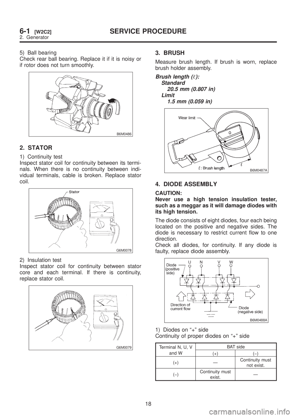
5) Ball bearing
Check rear ball bearing. Replace it if it is noisy or
if rotor does not turn smoothly.
B6M0486
2. STATOR
1) Continuity test
Inspect stator coil for continuity between its termi-
nals. When there is no continuity between indi-
vidual terminals, cable is broken. Replace stator
coil.
G6M0078
2) Insulation test
Inspect stator coil for continuity between stator
core and each terminal. If there is continuity,
replace stator coil.
G6M0079
3. BRUSH
Measure brush length. If brush is worn, replace
brush holder assembly.
Brush length ():
Standard
20.5 mm (0.807 in)
Limit
1.5 mm (0.059 in)
B6M0487A
4. DIODE ASSEMBLY
CAUTION:
Never use a high tension insulation tester,
such as a meggar as it will damage diodes with
its high tension.
The diode consists of eight diodes, four each being
located on the positive and negative sides. The
diode is necessary to restrict current flow to one
direction.
Check all diodes, for continuity. If any diode is
faulty, replace diode assembly.
B6M0488A
1) Diodes on ª+º side
Continuity of proper diodes on ª+º side
Terminal N, U, V
and WBAT side
(+) (þ)
(+) ÐContinuity must
not exist.
(þ)Continuity must
exist.Ð
18
6-1[W2C2]SERVICE PROCEDURE
2. Generator
Page 1201 of 1456

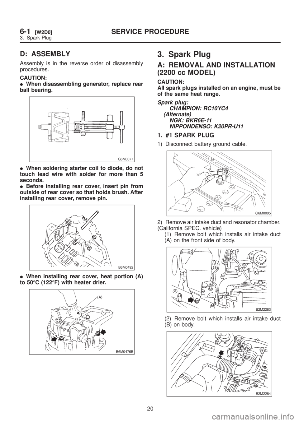
D: ASSEMBLY
Assembly is in the reverse order of disassembly
procedures.
CAUTION:
IWhen disassembling generator, replace rear
ball bearing.
G6M0077
IWhen soldering starter coil to diode, do not
touch lead wire with solder for more than 5
seconds.
IBefore installing rear cover, insert pin from
outside of rear cover so that holds brush. After
installing rear cover, remove pin.
B6M0492
IWhen installing rear cover, heat portion (A)
to 50ÉC (122ÉF) with heater drier.
B6M0476B
3. Spark Plug
A: REMOVAL AND INSTALLATION
(2200 cc MODEL)
CAUTION:
All spark plugs installed on an engine, must be
of the same heat range.
Spark plug:
CHAMPION: RC10YC4
(Alternate)
NGK: BKR6E-11
NIPPONDENSO: K20PR-U11
1. #1 SPARK PLUG
1) Disconnect battery ground cable.
G6M0095
2) Remove air intake duct and resonator chamber.
(California SPEC. vehicle)
(1) Remove bolt which installs air intake duct
(A) on the front side of body.
B2M2283
(2) Remove bolt which installs air intake duct
(B) on body.
B2M2284
20
6-1[W2D0]SERVICE PROCEDURE
3. Spark Plug
Page 1202 of 1456

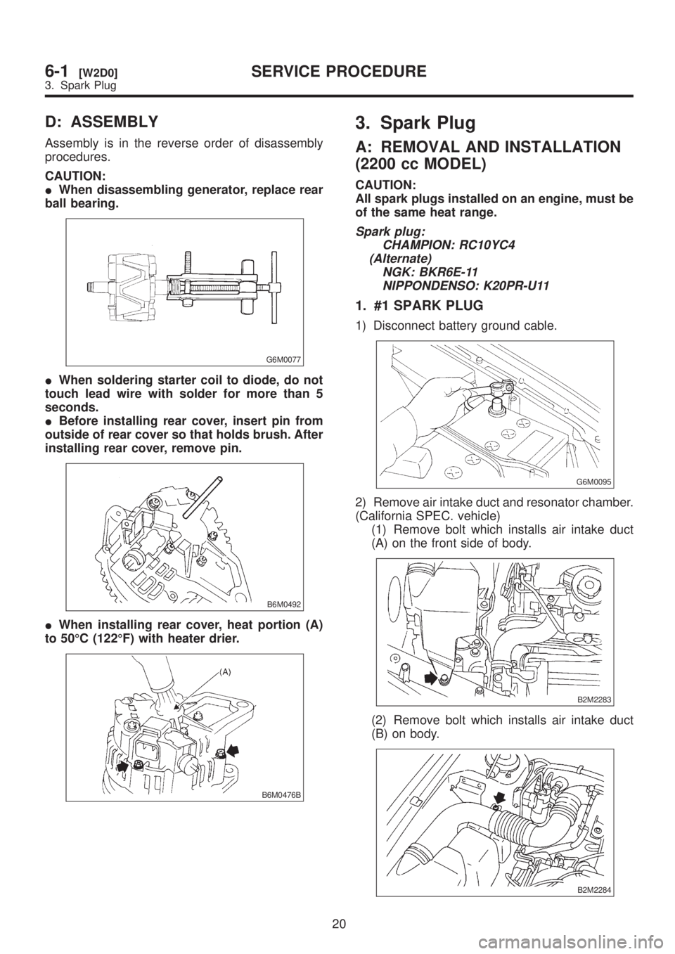
D: ASSEMBLY
Assembly is in the reverse order of disassembly
procedures.
CAUTION:
IWhen disassembling generator, replace rear
ball bearing.
G6M0077
IWhen soldering starter coil to diode, do not
touch lead wire with solder for more than 5
seconds.
IBefore installing rear cover, insert pin from
outside of rear cover so that holds brush. After
installing rear cover, remove pin.
B6M0492
IWhen installing rear cover, heat portion (A)
to 50ÉC (122ÉF) with heater drier.
B6M0476B
3. Spark Plug
A: REMOVAL AND INSTALLATION
(2200 cc MODEL)
CAUTION:
All spark plugs installed on an engine, must be
of the same heat range.
Spark plug:
CHAMPION: RC10YC4
(Alternate)
NGK: BKR6E-11
NIPPONDENSO: K20PR-U11
1. #1 SPARK PLUG
1) Disconnect battery ground cable.
G6M0095
2) Remove air intake duct and resonator chamber.
(California SPEC. vehicle)
(1) Remove bolt which installs air intake duct
(A) on the front side of body.
B2M2283
(2) Remove bolt which installs air intake duct
(B) on body.
B2M2284
20
6-1[W2D0]SERVICE PROCEDURE
3. Spark Plug
Page 1206 of 1456
4. #4 SPARK PLUG
1) Disconnect battery ground cable.
G6M0095
2) Disconnect washer motor connector.
S2M0546
3) Disconnect rear window glass washer hose
from washer motor, then plug connection with a
suitable cap.
4) Remove the two bolts which hold the washer
tank, then take the tank away from the working
area.
B2M2023
5) Remove #4 spark plug cord by pulling boot, not
cord itself.
B6M0929A
6) Remove spark plug with the spark plug socket.
B6M0926
7) Installation is in the reverse order of removal.
Tightening torque (Spark plug):
20.6
±2.9 N´m (2.10±0.30 kg-m, 15.19±2.14
ft-lb)
CAUTION:
The above torque should be only applied to
new spark plugs without oil on their threads.
In case their threads are lubricated, the torque
should be reduced by approximately 1/3 of the
specified torque in order to avoid over-stress-
ing.
24
6-1[W3A4]SERVICE PROCEDURE
3. Spark Plug
Page 1214 of 1456

D: INSTALLATION (2500 cc
OUTBACK MODEL)
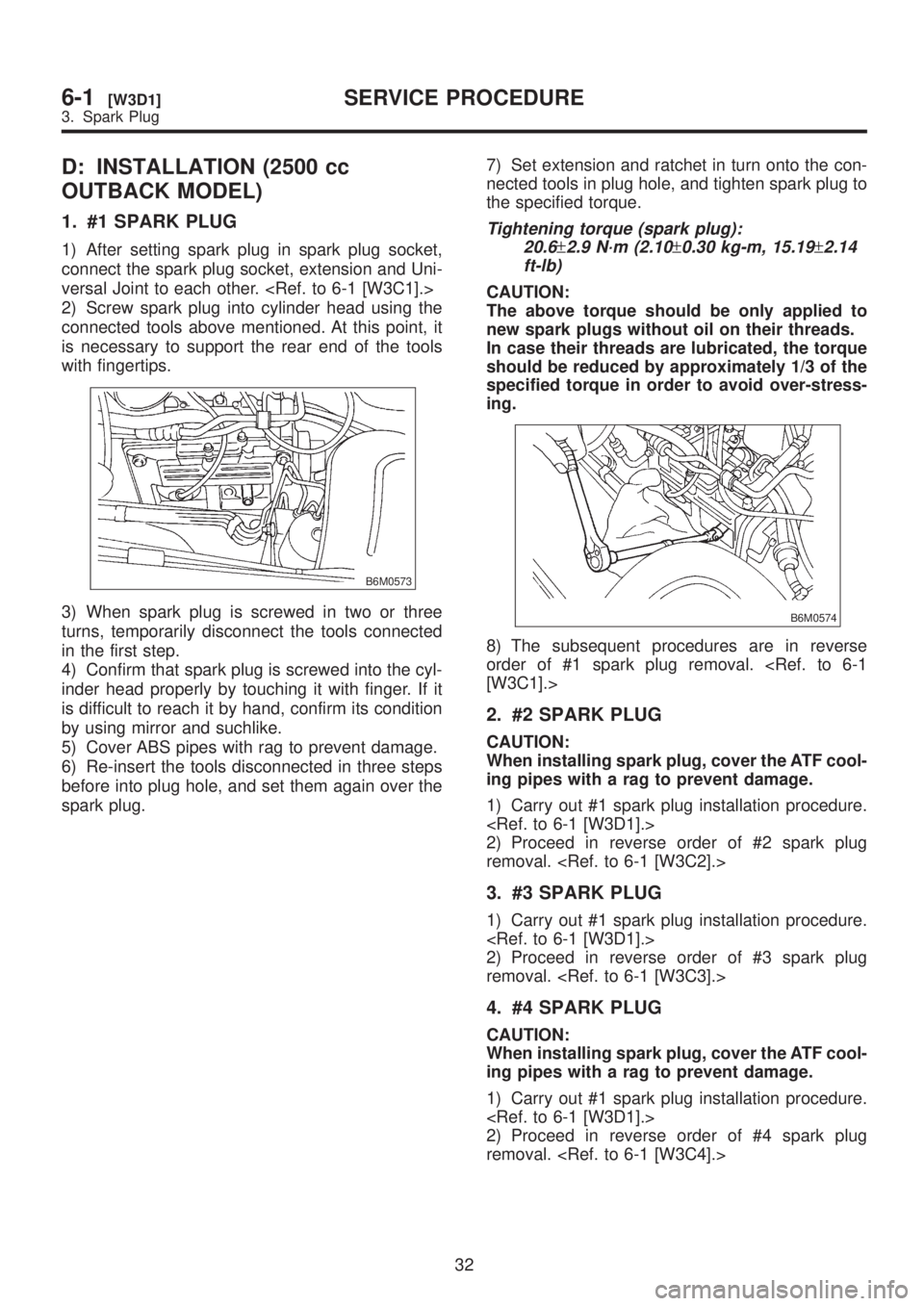
1. #1 SPARK PLUG
1) After setting spark plug in spark plug socket,
connect the spark plug socket, extension and Uni-
versal Joint to each other.
2) Screw spark plug into cylinder head using the
connected tools above mentioned. At this point, it
is necessary to support the rear end of the tools
with fingertips.
B6M0573
3) When spark plug is screwed in two or three
turns, temporarily disconnect the tools connected
in the first step.
4) Confirm that spark plug is screwed into the cyl-
inder head properly by touching it with finger. If it
is difficult to reach it by hand, confirm its condition
by using mirror and suchlike.
5) Cover ABS pipes with rag to prevent damage.
6) Re-insert the tools disconnected in three steps
before into plug hole, and set them again over the
spark plug.7) Set extension and ratchet in turn onto the con-
nected tools in plug hole, and tighten spark plug to
the specified torque.
Tightening torque (spark plug):
20.6
±2.9 N´m (2.10±0.30 kg-m, 15.19±2.14
ft-lb)
CAUTION:
The above torque should be only applied to
new spark plugs without oil on their threads.
In case their threads are lubricated, the torque
should be reduced by approximately 1/3 of the
specified torque in order to avoid over-stress-
ing.
B6M0574
8) The subsequent procedures are in reverse
order of #1 spark plug removal.
[W3C1].>
2. #2 SPARK PLUG
CAUTION:
When installing spark plug, cover the ATF cool-
ing pipes with a rag to prevent damage.
1) Carry out #1 spark plug installation procedure.
2) Proceed in reverse order of #2 spark plug
removal.
3. #3 SPARK PLUG
1) Carry out #1 spark plug installation procedure.
2) Proceed in reverse order of #3 spark plug
removal.
4. #4 SPARK PLUG
CAUTION:
When installing spark plug, cover the ATF cool-
ing pipes with a rag to prevent damage.
1) Carry out #1 spark plug installation procedure.
2) Proceed in reverse order of #4 spark plug
removal.
32
6-1[W3D1]SERVICE PROCEDURE
3. Spark Plug