Page 1154 of 1456
IEnsure that tongues, buckles and belts are
properly placed on seat.5. Inner Trim Panel
A: REMOVAL AND INSTALLATION
1. SIDE SILL COVER
1) Remove front pillar lower trim (A).
2) Remove side sill rear upper cover trim (B).
B5M0046C
3) Installation is in the reverse order of removal.
2. CENTER PILLAR LOWER
1) Remove center pillar lower trim.
B5M0047
2) Installation is in the reverse order of removal.
3. CENTER PILLAR UPPER
NOTE:
1) Remove front pillar upper trim.
2) Remove upper anchor of front seat belt.
3) Remove center pillar upper trim panel.
B5M0048A
4) Installation is in the reverse order of removal.
13
[W5A3]5-3SERVICE PROCEDURE
5. Inner Trim Panel
Page 1155 of 1456
IEnsure that tongues, buckles and belts are
properly placed on seat.5. Inner Trim Panel
A: REMOVAL AND INSTALLATION
1. SIDE SILL COVER
1) Remove front pillar lower trim (A).
2) Remove side sill rear upper cover trim (B).
B5M0046C
3) Installation is in the reverse order of removal.
2. CENTER PILLAR LOWER
1) Remove center pillar lower trim.
B5M0047
2) Installation is in the reverse order of removal.
3. CENTER PILLAR UPPER
NOTE:
1) Remove front pillar upper trim.
2) Remove upper anchor of front seat belt.
3) Remove center pillar upper trim panel.
B5M0048A
4) Installation is in the reverse order of removal.
13
[W5A3]5-3SERVICE PROCEDURE
5. Inner Trim Panel
Page 1156 of 1456

CAUTION:
IThe left and right ELR's are not mutually
interchangeable because different sensors are
used.
IBe careful not to twist belts during installa-
tion.
4. FRONT PILLAR UPPER
NOTE:
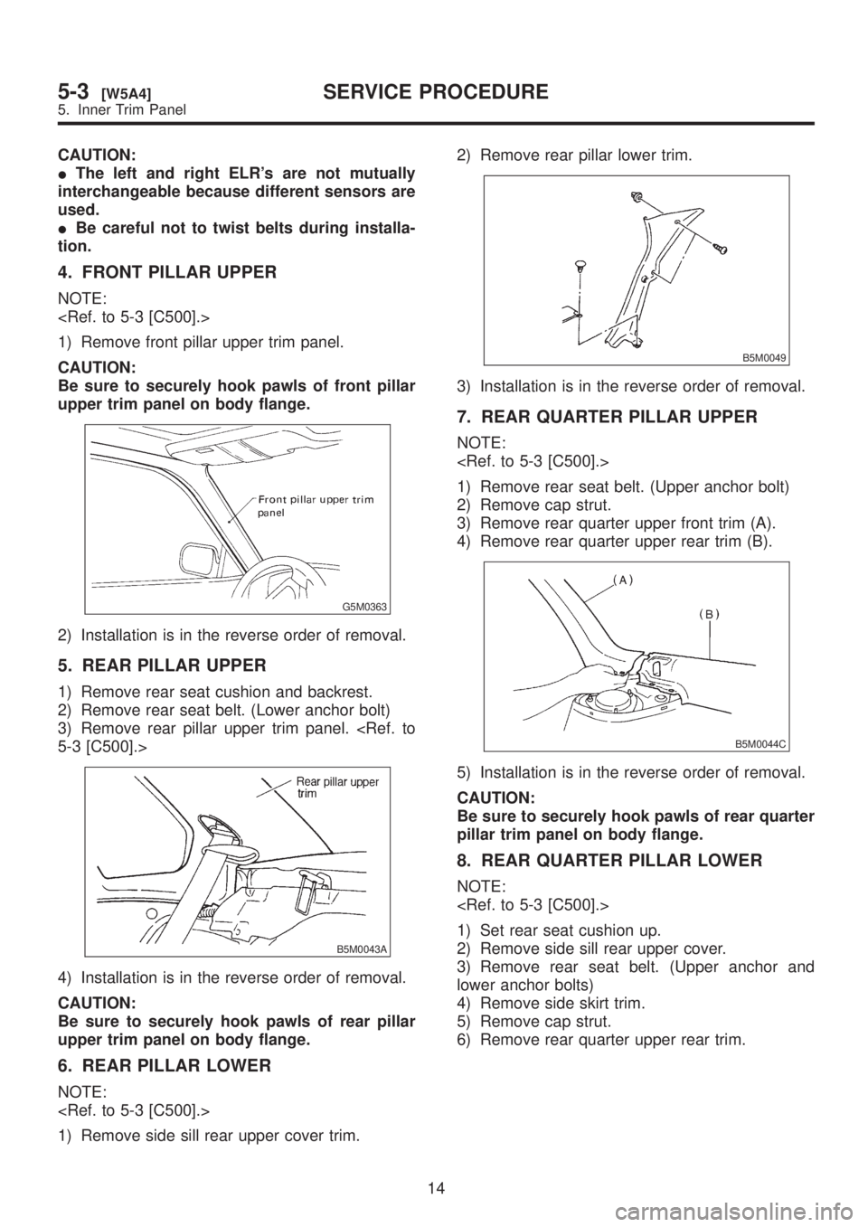
1) Remove front pillar upper trim panel.
CAUTION:
Be sure to securely hook pawls of front pillar
upper trim panel on body flange.
G5M0363
2) Installation is in the reverse order of removal.
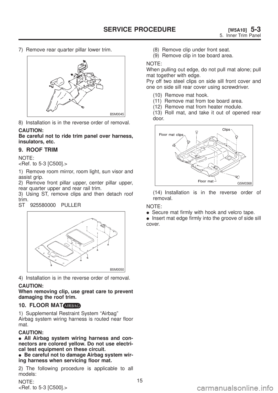
5. REAR PILLAR UPPER
1) Remove rear seat cushion and backrest.
2) Remove rear seat belt. (Lower anchor bolt)
3) Remove rear pillar upper trim panel.
5-3 [C500].>
B5M0043A
4) Installation is in the reverse order of removal.
CAUTION:
Be sure to securely hook pawls of rear pillar
upper trim panel on body flange.
6. REAR PILLAR LOWER
NOTE:
1) Remove side sill rear upper cover trim.2) Remove rear pillar lower trim.
B5M0049
3) Installation is in the reverse order of removal.
7. REAR QUARTER PILLAR UPPER
NOTE:
1) Remove rear seat belt. (Upper anchor bolt)
2) Remove cap strut.
3) Remove rear quarter upper front trim (A).
4) Remove rear quarter upper rear trim (B).
B5M0044C
5) Installation is in the reverse order of removal.
CAUTION:
Be sure to securely hook pawls of rear quarter
pillar trim panel on body flange.
8. REAR QUARTER PILLAR LOWER
NOTE:
1) Set rear seat cushion up.
2) Remove side sill rear upper cover.
3) Remove rear seat belt. (Upper anchor and
lower anchor bolts)
4) Remove side skirt trim.
5) Remove cap strut.
6) Remove rear quarter upper rear trim.
14
5-3[W5A4]SERVICE PROCEDURE
5. Inner Trim Panel
Page 1157 of 1456

7) Remove rear quarter pillar lower trim.
B5M0045
8) Installation is in the reverse order of removal.
CAUTION:
Be careful not to ride trim panel over harness,
insulators, etc.
9. ROOF TRIM
NOTE:
1) Remove room mirror, room light, sun visor and
assist grip.
2) Remove front pillar upper, center pillar upper,
rear quarter upper and rear rail trim.
3) Using ST, remove clips and then detach roof
trim.
ST 925580000 PULLER
B5M0050
4) Installation is in the reverse order of removal.
CAUTION:
When removing clip, use great care to prevent
damaging the roof trim.
10. FLOOR MAT
1) Supplemental Restraint System ªAirbagº
Airbag system wiring harness is routed near floor
mat.
CAUTION:
IAll Airbag system wiring harness and con-
nectors are colored yellow. Do not use electri-
cal test equipment on these circuit.
IBe careful not to damage Airbag system wir-
ing harness when servicing floor mat.
2) The following procedure is applicable to all
models:
NOTE:
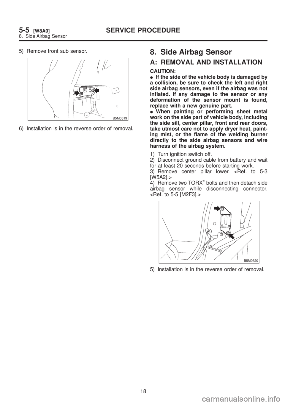
(8) Remove clip under front seat.
(9) Remove clip in toe board area.
NOTE:
When pulling out edge, do not pull mat alone; pull
mat together with edge.
Pry off two steel clips on side sill front cover and
one on side sill rear cover using screwdriver.
(10) Remove mat hook.
(11) Remove mat from toe board area.
(12) Remove mat from heater module.
(13) Roll mat, and take it out of opened rear
door.
G5M0368
(14) Installation is in the reverse order of
removal.
NOTE:
ISecure mat firmly with hook and velcro tape.
IInsert mat edge firmly into the groove of side sill
cover.
15
[W5A10]5-3SERVICE PROCEDURE
5. Inner Trim Panel
Page 1181 of 1456

5) Remove front sub sensor.
B5M0519
6) Installation is in the reverse order of removal.
8. Side Airbag Sensor
A: REMOVAL AND INSTALLATION
CAUTION:
IIf the side of the vehicle body is damaged by
a collision, be sure to check the left and right
side airbag sensors, even if the airbag was not
inflated. If any damage to the sensor or any
deformation of the sensor mount is found,
replace with a new genuine part.
IWhen painting or performing sheet metal
work on the side part of vehicle body, including
the side sill, center pillar, front and rear doors,
take utmost care not to apply dryer heat, paint-
ing mist, or the flame of the welding burner
directly to the side airbag sensors and wire
harness of the airbag system.
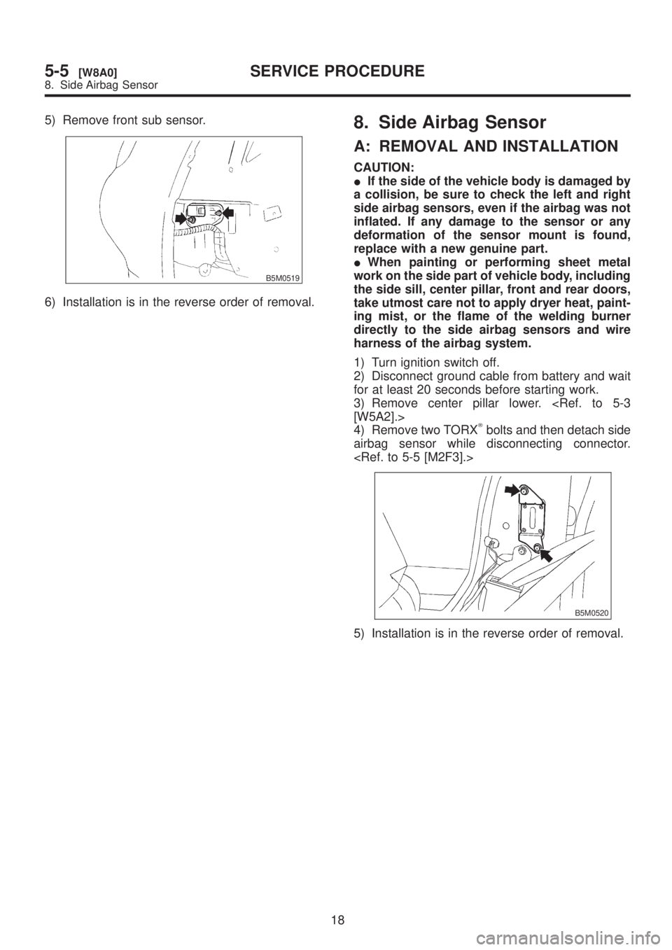
1) Turn ignition switch off.
2) Disconnect ground cable from battery and wait
for at least 20 seconds before starting work.
3) Remove center pillar lower.
[W5A2].>
4) Remove two TORX
Tbolts and then detach side
airbag sensor while disconnecting connector.
B5M0520
5) Installation is in the reverse order of removal.
18
5-5[W8A0]SERVICE PROCEDURE
8. Side Airbag Sensor
Page 1182 of 1456

5) Remove front sub sensor.
B5M0519
6) Installation is in the reverse order of removal.
8. Side Airbag Sensor
A: REMOVAL AND INSTALLATION
CAUTION:
IIf the side of the vehicle body is damaged by
a collision, be sure to check the left and right
side airbag sensors, even if the airbag was not
inflated. If any damage to the sensor or any
deformation of the sensor mount is found,
replace with a new genuine part.
IWhen painting or performing sheet metal
work on the side part of vehicle body, including
the side sill, center pillar, front and rear doors,
take utmost care not to apply dryer heat, paint-
ing mist, or the flame of the welding burner
directly to the side airbag sensors and wire
harness of the airbag system.
1) Turn ignition switch off.
2) Disconnect ground cable from battery and wait
for at least 20 seconds before starting work.
3) Remove center pillar lower.
[W5A2].>
4) Remove two TORX
Tbolts and then detach side
airbag sensor while disconnecting connector.
B5M0520
5) Installation is in the reverse order of removal.
18
5-5[W8A0]SERVICE PROCEDURE
8. Side Airbag Sensor
Page 1185 of 1456
1. Starter
A: MT VEHICLES
1. MODEL: TN128000-8311
B6M0412B
(1) Front ball bearing
(2) Armature
(3) Rear ball bearing
(4) O-ring
(5) Yoke
(6) Brush spring
(7) Brush holder
(8) End frame(9) Screw & washer
(10) Cover
(11) Through bolt
(12) Screw & washer
(13) Starter housing
(14) Overrunning clutch
(15) Steel ball
(16) Spring(17) Retainer
(18) Roller
(19) Idle gear
(20) Nut
(21) Spring washer
(22) Magnet switch
(23) Nut
4
6-1[C1A1]COMPONENT PARTS
1. Starter
Page 1186 of 1456
B: AT VEHICLES
1. MODEL: TN128000-8321
B6M0413B
(1) Front ball bearing
(2) Armature
(3) Rear ball bearing
(4) O-ring
(5) Yoke
(6) Brush spring
(7) Brush holder
(8) End frame(9) Cover
(10) Screw & washer
(11) Through bolt
(12) Screw & washer
(13) Starter housing
(14) Overrunning clutch
(15) Steel ball
(16) Spring(17) Retainer
(18) Roller
(19) Idle gear
(20) Nut
(21) Spring washer
(22) Magnet switch
(23) Nut
5
[C1B1]6-1COMPONENT PARTS
1. Starter