Page 57 of 1456

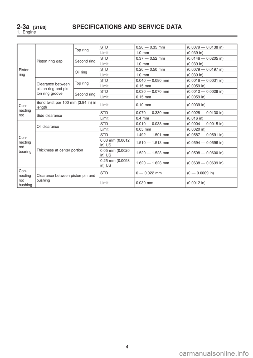
Piston
ringPiston ring gapTop ringSTD 0.20 Ð 0.35 mm (0.0079 Ð 0.0138 in)
Limit 1.0 mm (0.039 in)
Second ringSTD 0.37 Ð 0.52 mm (0.0146 Ð 0.0205 in)
Limit 1.0 mm (0.039 in)
Oil ringSTD 0.20 Ð 0.50 mm (0.0079 Ð 0.0197 in)
Limit 1.0 mm (0.039 in)
Clearance between
piston ring and pis-
ton ring grooveTop ringSTD 0.040 Ð 0.080 mm (0.0016 Ð 0.0031 in)
Limit 0.15 mm (0.0059 in)
Second ringSTD 0.030 Ð 0.070 mm (0.0012 Ð 0.0028 in)
Limit 0.15 mm (0.0059 in)
Con-
necting
rodBend twist per 100 mm (3.94 in) in
lengthLimit 0.10 mm (0.0039 in)
Side clearanceSTD 0.070 Ð 0.330 mm (0.0028 Ð 0.0130 in)
Limit 0.4 mm (0.016 in)
Con-
necting
rod
bearingOil clearanceSTD 0.010 Ð 0.038 mm (0.0004 Ð 0.0015 in)
Limit 0.05 mm (0.0020 in)
Thickness at center portionSTD 1.492 Ð 1.501 mm (0.0587 Ð 0.0591 in)
0.03 mm (0.0012
in) US1.510 Ð 1.513 mm (0.0594 Ð 0.0596 in)
0.05 mm (0.0020
in) US1.520 Ð 1.523 mm (0.0598 Ð 0.0600 in)
0.25 mm (0.0098
in) US1.620 Ð 1.623 mm (0.0638 Ð 0.0639 in)
Con-
necting
rod
bushingClearance between piston pin and
bushingSTD 0 Ð 0.022 mm (0 Ð 0.0009 in)
Limit 0.030 mm (0.0012 in)
4
2-3a[S1B0]SPECIFICATIONS AND SERVICE DATA
1. Engine
Page 58 of 1456

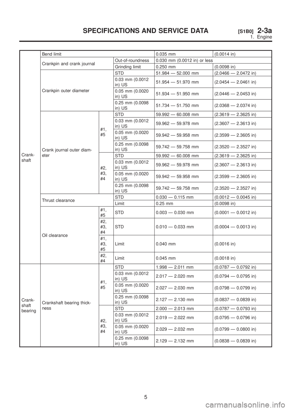
Crank-
shaftBend limit 0.035 mm (0.0014 in)
Crankpin and crank journalOut-of-roundness 0.030 mm (0.0012 in) or less
Grinding limit 0.250 mm (0.0098 in)
Crankpin outer diameterSTD 51.984 Ð 52.000 mm (2.0466 Ð 2.0472 in)
0.03 mm (0.0012
in) US51.954 Ð 51.970 mm (2.0454 Ð 2.0461 in)
0.05 mm (0.0020
in) US51.934 Ð 51.950 mm (2.0446 Ð 2.0453 in)
0.25 mm (0.0098
in) US51.734 Ð 51.750 mm (2.0368 Ð 2.0374 in)
Crank journal outer diam-
eter#1,
#5STD 59.992 Ð 60.008 mm (2.3619 Ð 2.3625 in)
0.03 mm (0.0012
in) US59.962 Ð 59.978 mm (2.3607 Ð 2.3613 in)
0.05 mm (0.0020
in) US59.942 Ð 59.958 mm (2.3599 Ð 2.3605 in)
0.25 mm (0.0098
in) US59.742 Ð 59.758 mm (2.3520 Ð 2.3527 in)
#2,
#3,
#4STD 59.992 Ð 60.008 mm (2.3619 Ð 2.3625 in)
0.03 mm (0.0012
in) US59.962 Ð 59.978 mm (2.3607 Ð 2.3613 in)
0.05 mm (0.0020
in) US59.942 Ð 59.958 mm (2.3599 Ð 2.3605 in)
0.25 mm (0.0098
in) US59.742 Ð 59.758 mm (2.3520 Ð 2.3527 in)
Thrust clearanceSTD 0.030 Ð 0.115 mm (0.0012 Ð 0.0045 in)
Limit 0.25 mm (0.0098 in)
Oil clearance#1,
#5STD 0.003 Ð 0.030 mm (0.0001 Ð 0.0012 in)
#2,
#3,
#4STD 0.010 Ð 0.033 mm (0.0004 Ð 0.0013 in)
#1,
#3,
#5Limit 0.040 mm (0.0016 in)
#2,
#4Limit 0.045 mm (0.0018 in)
Crank-
shaft
bearingCrankshaft bearing thick-
ness#1,
#5STD 1.998 Ð 2.011 mm (0.0787 Ð 0.0792 in)
0.03 mm (0.0012
in) US2.017 Ð 2.020 mm (0.0794 Ð 0.0795 in)
0.05 mm (0.0020
in) US2.027 Ð 2.030 mm (0.0798 Ð 0.0799 in)
0.25 mm (0.0098
in) US2.127 Ð 2.130 mm (0.0837 Ð 0.0839 in)
#2,
#3,
#4STD 2.000 Ð 2.013 mm (0.0787 Ð 0.0793 in)
0.03 mm (0.0012
in) US2.019 Ð 2.022 mm (0.0795 Ð 0.0796 in)
0.05 mm (0.0020
in) US2.029 Ð 2.032 mm (0.0799 Ð 0.0800 in)
0.25 mm (0.0098
in) US2.129 Ð 2.132 mm (0.0838 Ð 0.0839 in)
5
[S1B0]2-3aSPECIFICATIONS AND SERVICE DATA
1. Engine
Page 65 of 1456
1. General Precautions
A: GENERAL PRECAUTIONS
1) Before disassembling engine, place it on ST3.
ST1 498457000 ENGINE STAND ADAPTER
RH
ST2 498457100 ENGINE STAND ADAPTER
LH
ST3 499817000 ENGINE STAND
B2M2582A
2) All parts should be thoroughly cleaned, paying
special attention to the engine oil passages, pis-
tons and bearings.
3) Rotating parts and sliding parts such as piston,
bearing and gear should be coated with oil prior to
assembly.
4) Be careful not to let oil, grease or coolant con-
tact the timing belt, clutch disc and flywheel.
5) All removed parts, if to be reused, should be
reinstalled in the original positions and directions.
6) All removed parts, if to be reused, should be
reinstalled in the original positions and directions.
7) Bolts, nuts and washers should be replaced
with new ones as required.
8) Even if necessary inspections have been made
in advance, proceed with assembly work while
making rechecks.
12
2-3a[W1A0]SERVICE PROCEDURE
1. General Precautions
Page 78 of 1456

4. CRANKSHAFT PULLEY AND BELT COVER
B2M2583B
(1) Front belt cover
(2) Belt cover (LH)
(3) Crankshaft pulley
(4) Crankshaft pulley bolt(5) Rear side V-belt (With A/C
model)
(6) Front side V-beltTightening torque: N´m (kg-m, ft-lb)
T1:
5±1 (0.5±0.1, 3.6±0.7)
T2:127+10/þ5(13.0+1.0/þ0.5,
94+7.2/þ3.6)
1) Install front belt cover.
2) Install belt cover (LH).
B2M2587A
3) Install crankshaft pulley.
4) Install pulley bolt.
To lock crankshaft, use ST.
ST 499977000 CRANKSHAFT PULLEY
WRENCH
(1) Clean the crankshaft pulley thread using an
air gun.
(2) Apply engine oil to the crankshaft pulley bolt
seat and thread.
(3) Tighten the bolts temporarily with tightening
torque of 44 N´m (4.5 kg-m, 33 ft-lb).
(4) Tighten the crankshaft pulley bolts.
Tightening torque:
127
±5 N´m (13.0±0.5 kg-m, 94.0±3.6 ft-lb)
B2M2586A
5) Confirm that the tightening angle of the crank-
shaft pulley bolt is 45 degrees or more. If not, con-
duct the following procedures (1) through (4).
25
[W2C4]2-3aSERVICE PROCEDURE
2. Timing Belt
Page 90 of 1456
C: INSTALLATION
1. CAMSHAFT (LH)
B2M2610B
(1) Camshaft (LH)
(2) Camshaft cap(3) Plug
(4) Oil seal(5) Oil level gauge guide
(6) Bolt
1) Apply a coat of engine oil to camshaft journals
and install camshaft (LH).
2) Install camshaft cap.
(1) Apply liquid gasket on the around of cam-
shaft cap.
Liquid gasket:
THREE BOND 1280B (Part No.
0029431130)
B2M2619
(2) Temporarily tighten bolts (g) through (j) in
alphabetical sequence.
B2M2612A
(3) Install valve rocker assembly.
B2M2606
36
2-3a[W4C1]SERVICE PROCEDURE
4. Camshaft
Page 92 of 1456
2. CAMSHAFT (RH)
B2M2614A
(1) Camshaft support (RH)
(2) O-ring(3) Camshaft (RH)
(4) Oil seal(5) Plug
1) Apply a coat of engine oil to camshaft journals
and install camshaft (RH).
2) Install camshaft cap.
(1) Apply liquid gasket on the around of cam-
shaft cap.
Liquid gasket:
THREE BOND 1280B (Part No.
0029431130)
B2M2619
(2) Temporarily tighten bolts (g) through (j) in
alphabetical sequence.
B2M2612A
(3) Install valve rocker assembly.
B2M2615
38
2-3a[W4C2]SERVICE PROCEDURE
4. Camshaft
Page 94 of 1456
5. Cylinder Head
A: REMOVAL
1. RELATED PARTS
1) Release fuel pressure.
2) Drain engine coolant.
3) Remove V-belt(s).
4) Remove generator and bracket.
5) Remove A/C compressor and bracket. (With
A/C model)6) Disconnect spark plug cords.
7) Remove connector bracket attaching bolt.
8) Remove camshaft position sensor and cam-
shaft position sensor support.
9) Disconnect oil pressure switch connector.
10) Disconnect blow-by hose.
11) Remove intake manifold.
[W4A0].>
2. CYLINDER HEAD
B2M2627A
(1) Rocker cover
(2) Cylinder head bolt(3) Cylinder head
(4) Cylinder head gasket
1) Remove timing belt, camshaft sprocket and
related parts.
2) Remove oil level gauge guide attaching bolt
(left hand only) and oil level gauge guide.
3) Remove rocker cover.
40
2-3a[W5A1]SERVICE PROCEDURE
5. Cylinder Head
Page 99 of 1456

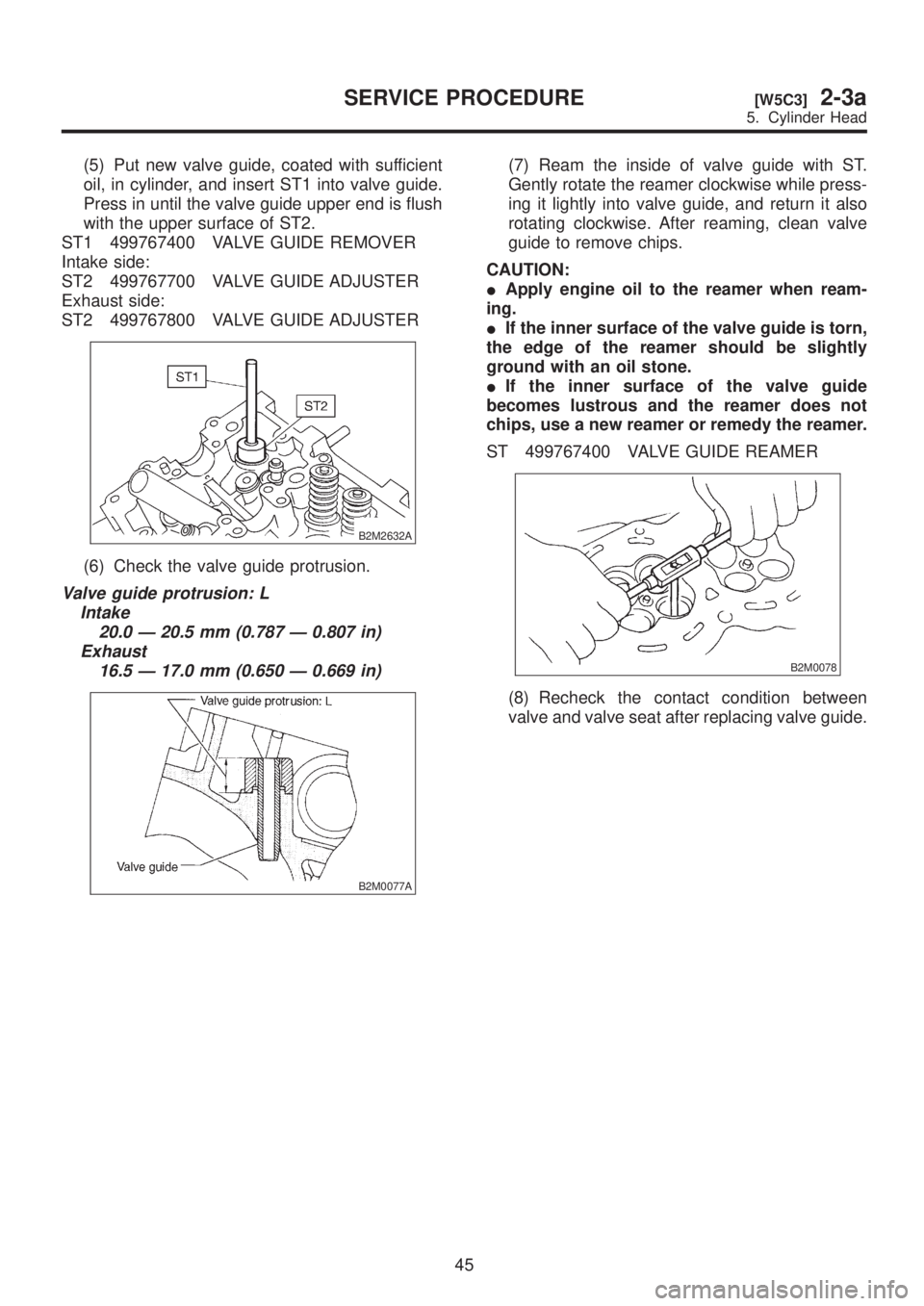
(5) Put new valve guide, coated with sufficient
oil, in cylinder, and insert ST1 into valve guide.
Press in until the valve guide upper end is flush
with the upper surface of ST2.
ST1 499767400 VALVE GUIDE REMOVER
Intake side:
ST2 499767700 VALVE GUIDE ADJUSTER
Exhaust side:
ST2 499767800 VALVE GUIDE ADJUSTER
B2M2632A
(6) Check the valve guide protrusion.
Valve guide protrusion: L
Intake
20.0 Ð 20.5 mm (0.787 Ð 0.807 in)
Exhaust
16.5 Ð 17.0 mm (0.650 Ð 0.669 in)
B2M0077A
(7) Ream the inside of valve guide with ST.
Gently rotate the reamer clockwise while press-
ing it lightly into valve guide, and return it also
rotating clockwise. After reaming, clean valve
guide to remove chips.
CAUTION:
IApply engine oil to the reamer when ream-
ing.
IIf the inner surface of the valve guide is torn,
the edge of the reamer should be slightly
ground with an oil stone.
IIf the inner surface of the valve guide
becomes lustrous and the reamer does not
chips, use a new reamer or remedy the reamer.
ST 499767400 VALVE GUIDE REAMER
B2M0078
(8) Recheck the contact condition between
valve and valve seat after replacing valve guide.
45
[W5C3]2-3aSERVICE PROCEDURE
5. Cylinder Head