Page 136 of 1456

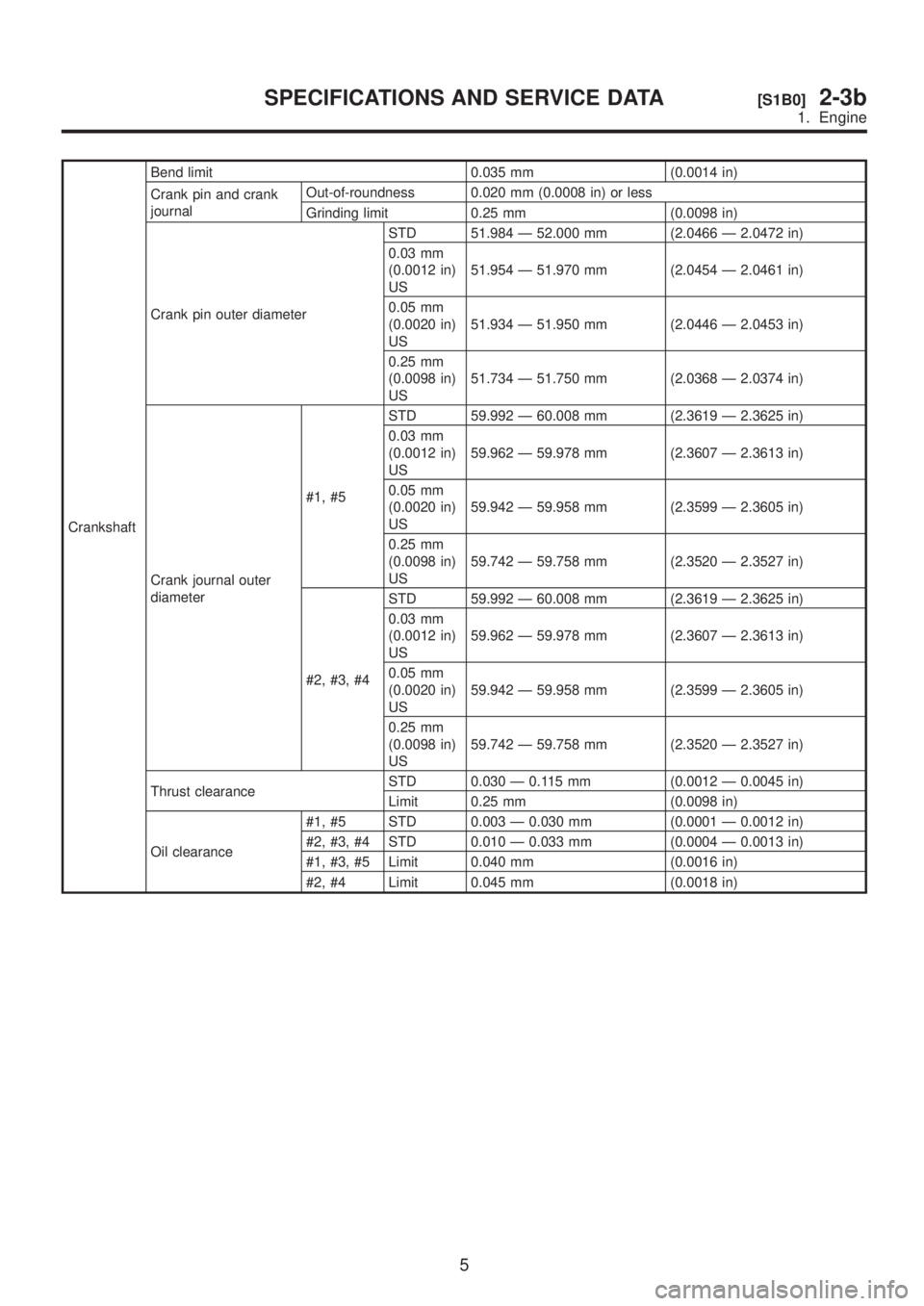
CrankshaftBend limit 0.035 mm (0.0014 in)
Crank pin and crank
journalOut-of-roundness 0.020 mm (0.0008 in) or less
Grinding limit 0.25 mm (0.0098 in)
Crank pin outer diameterSTD 51.984 Ð 52.000 mm (2.0466 Ð 2.0472 in)
0.03 mm
(0.0012 in)
US51.954 Ð 51.970 mm (2.0454 Ð 2.0461 in)
0.05 mm
(0.0020 in)
US51.934 Ð 51.950 mm (2.0446 Ð 2.0453 in)
0.25 mm
(0.0098 in)
US51.734 Ð 51.750 mm (2.0368 Ð 2.0374 in)
Crank journal outer
diameter#1, #5STD 59.992 Ð 60.008 mm (2.3619 Ð 2.3625 in)
0.03 mm
(0.0012 in)
US59.962 Ð 59.978 mm (2.3607 Ð 2.3613 in)
0.05 mm
(0.0020 in)
US59.942 Ð 59.958 mm (2.3599 Ð 2.3605 in)
0.25 mm
(0.0098 in)
US59.742 Ð 59.758 mm (2.3520 Ð 2.3527 in)
#2, #3, #4STD 59.992 Ð 60.008 mm (2.3619 Ð 2.3625 in)
0.03 mm
(0.0012 in)
US59.962 Ð 59.978 mm (2.3607 Ð 2.3613 in)
0.05 mm
(0.0020 in)
US59.942 Ð 59.958 mm (2.3599 Ð 2.3605 in)
0.25 mm
(0.0098 in)
US59.742 Ð 59.758 mm (2.3520 Ð 2.3527 in)
Thrust clearanceSTD 0.030 Ð 0.115 mm (0.0012 Ð 0.0045 in)
Limit 0.25 mm (0.0098 in)
Oil clearance#1, #5 STD 0.003 Ð 0.030 mm (0.0001 Ð 0.0012 in)
#2, #3, #4 STD 0.010 Ð 0.033 mm (0.0004 Ð 0.0013 in)
#1, #3, #5 Limit 0.040 mm (0.0016 in)
#2, #4 Limit 0.045 mm (0.0018 in)
5
[S1B0]2-3bSPECIFICATIONS AND SERVICE DATA
1. Engine
Page 137 of 1456
Crankshaft
bearingCrankshaft bearing
thickness#1, #5STD 1.998 Ð 2.011 mm (0.0787 Ð 0.0792 in)
0.03 mm
(0.0012 in)
US2.017 Ð 2.020 mm (0.0794 Ð 0.0795 in)
0.05 mm
(0.0020 in)
US2.027 Ð 2.030 mm (0.0798 Ð 0.0799 in)
0.25 mm
(0.0098 in)
US2.127 Ð 2.130 mm (0.0837 Ð 0.0839 in)
#2, #3, #4STD 2.000 Ð 2.013 mm (0.0787 Ð 0.0793 in)
0.03 mm
(0.0012 in)
US2.019 Ð 2.022 mm (0.0795 Ð 0.0796 in)
0.05 mm
(0.0020 in)
US2.029 Ð 2.032 mm (0.0799 Ð 0.0800 in)
0.25 mm
(0.0098 in)
US2.129 Ð 2.132 mm (0.0838 Ð 0.0839 in)
6
2-3b[S1B0]SPECIFICATIONS AND SERVICE DATA
1. Engine
Page 144 of 1456

1. Precautions
A: GENERAL PRECAUTIONS
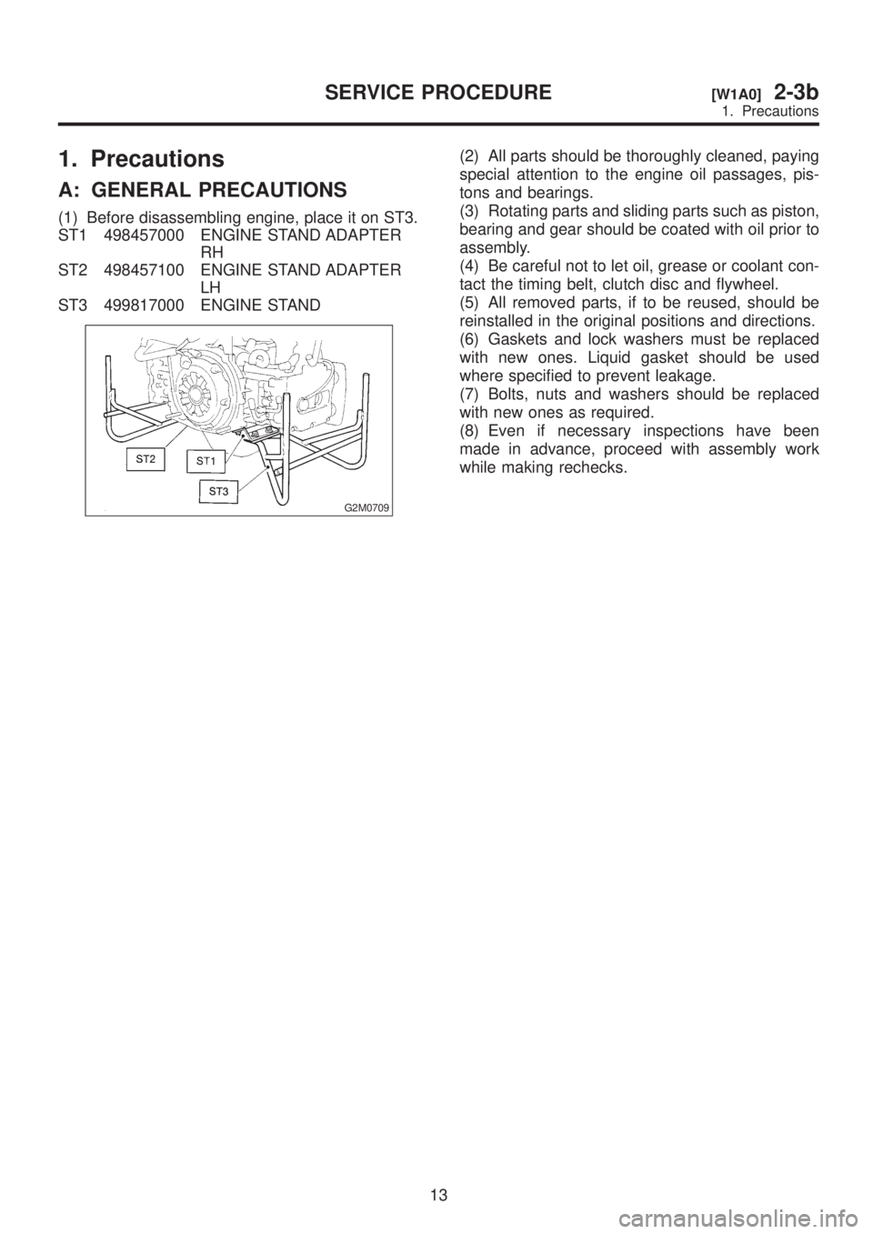
(1) Before disassembling engine, place it on ST3.
ST1 498457000 ENGINE STAND ADAPTER
RH
ST2 498457100 ENGINE STAND ADAPTER
LH
ST3 499817000 ENGINE STAND
G2M0709
(2) All parts should be thoroughly cleaned, paying
special attention to the engine oil passages, pis-
tons and bearings.
(3) Rotating parts and sliding parts such as piston,
bearing and gear should be coated with oil prior to
assembly.
(4) Be careful not to let oil, grease or coolant con-
tact the timing belt, clutch disc and flywheel.
(5) All removed parts, if to be reused, should be
reinstalled in the original positions and directions.
(6) Gaskets and lock washers must be replaced
with new ones. Liquid gasket should be used
where specified to prevent leakage.
(7) Bolts, nuts and washers should be replaced
with new ones as required.
(8) Even if necessary inspections have been
made in advance, proceed with assembly work
while making rechecks.
13
[W1A0]2-3bSERVICE PROCEDURE
1. Precautions
Page 156 of 1456
(4) Align single line mark on left-hand exhaust
camshaft sprocket with notch on belt cover by
turning sprocket counter-clockwise (as viewed
from front of engine).
B2M0696A
(5) Align single line mark on left-hand intake
camshaft sprocket with notch on belt cover by
turning sprocket clockwise (as viewed from front
of engine).
Ensure double lines on intake and exhaust cam-
shaft sprockets are aligned.
B2M0697A
(6) Ensure camshaft and crankshaft sprockets are positioned as shown.
G2M0734
25
[W2C3]2-3bSERVICE PROCEDURE
2. Timing Belt
Page 157 of 1456

CAUTION:
IIntake and exhaust camshafts for this DOHC
engine can be independently rotated with tim-
ing belts removed. As can be seen from the
figure, if intake and exhaust valves are lifted
simultaneously, their heads will interfere with
each other, resulting in bent valves.
B2M1392A
IWhen timing belts are not installed, four
camshafts are held at the ªzero-liftº position,
where all cams on camshafts do not push
intake and exhaust valves down. (Under this
condition, all valves remain unlifted.)
IWhen camshafts are rotated to install timing
belts, #2 intake and #4 exhaust cam of left-hand
camshafts are held to push their correspond-
ing valves down. (Under this condition, these
valves are held lifted.) Right-side camshafts
are held so that their cams do not push valves
down.
ILeft-hand camshafts must be rotated from
the ªzero-liftº position to the position where
timing belt is to be installed at as small an
angle as possible, in order to prevent mutual
interference of intake and exhaust valve heads.
IDo not allow camshafts to rotate in the direc-
tion shown in the figure as this causes both
intake and exhaust valves to lift
simultaneously, resulting in interference with
their heads.
B2M0698A
26
2-3b[W2C3]SERVICE PROCEDURE
2. Timing Belt
Page 165 of 1456

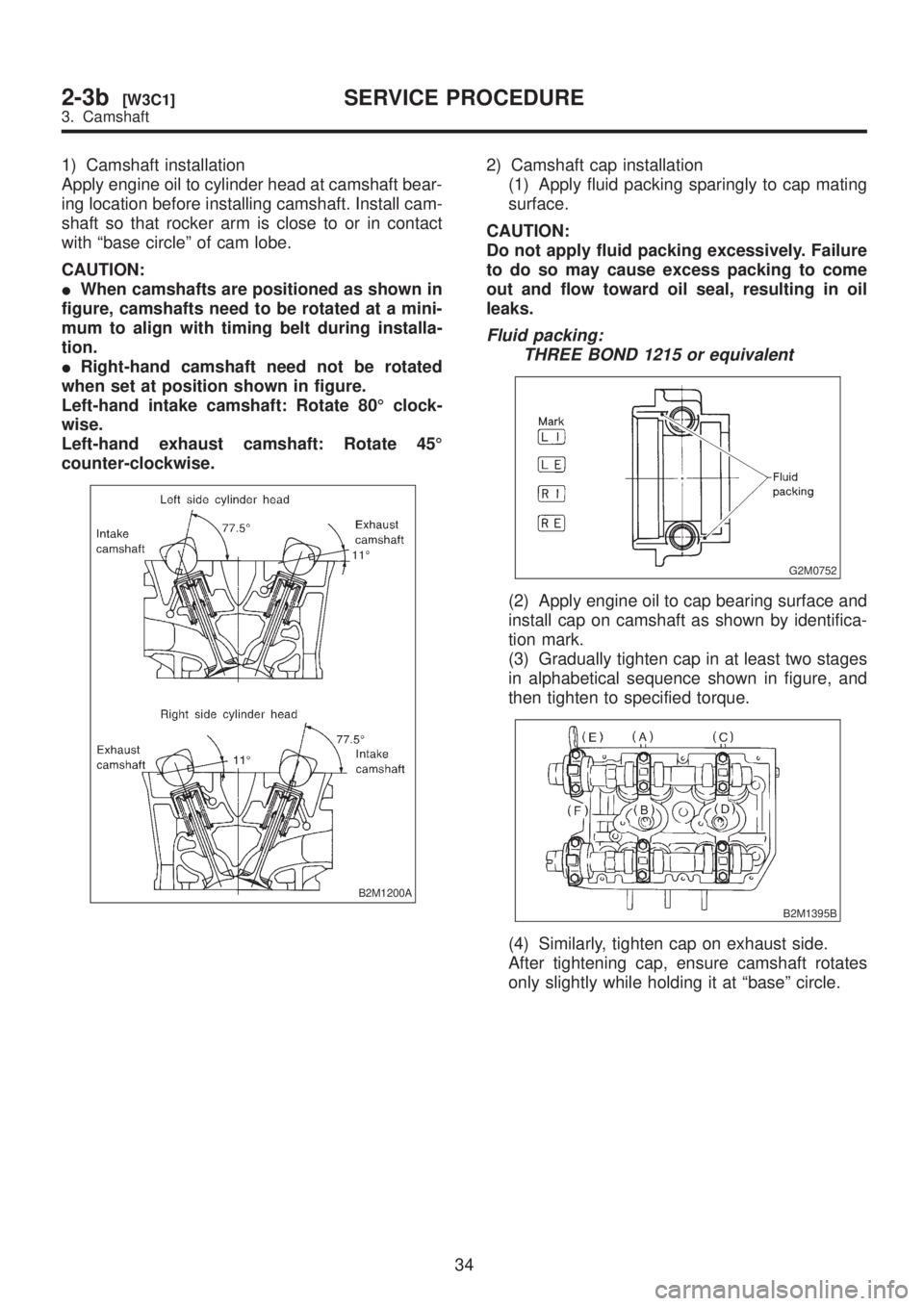
1) Camshaft installation
Apply engine oil to cylinder head at camshaft bear-
ing location before installing camshaft. Install cam-
shaft so that rocker arm is close to or in contact
with ªbase circleº of cam lobe.
CAUTION:
IWhen camshafts are positioned as shown in
figure, camshafts need to be rotated at a mini-
mum to align with timing belt during installa-
tion.
IRight-hand camshaft need not be rotated
when set at position shown in figure.
Left-hand intake camshaft: Rotate 80É clock-
wise.
Left-hand exhaust camshaft: Rotate 45É
counter-clockwise.
B2M1200A
2) Camshaft cap installation
(1) Apply fluid packing sparingly to cap mating
surface.
CAUTION:
Do not apply fluid packing excessively. Failure
to do so may cause excess packing to come
out and flow toward oil seal, resulting in oil
leaks.
Fluid packing:
THREE BOND 1215 or equivalent
G2M0752
(2) Apply engine oil to cap bearing surface and
install cap on camshaft as shown by identifica-
tion mark.
(3) Gradually tighten cap in at least two stages
in alphabetical sequence shown in figure, and
then tighten to specified torque.
B2M1395B
(4) Similarly, tighten cap on exhaust side.
After tightening cap, ensure camshaft rotates
only slightly while holding it at ªbaseº circle.
34
2-3b[W3C1]SERVICE PROCEDURE
3. Camshaft
Page 171 of 1456

(5) Put new valve guide, coated with sufficient
oil, in cylinder, and insert ST1 into valve guide.
Press in until the valve guide upper end is flush
with the upper surface of ST2.
ST1 499767200 VALVE GUIDE REMOVER
ST2 498267700 VALVE GUIDE ADJUSTER
B2M1398A
(6) Check the valve guide protrusion.
Valve guide protrusion: L
12.0 Ð 12.4 mm (0.472 Ð 0.488 in)
(7) Ream the inside of valve guide with ST.
Gently rotate the reamer clockwise while press-
ing it lightly into valve guide, and return it also
rotating clockwise. After reaming, clean valve
guide to remove chips.
ST 499767400 VALVE GUIDE REAMER
CAUTION:
IApply engine oil to the reamer when ream-
ing.
IIf the inner surface of the valve guide is torn,
the edge of the reamer should be slightly
ground with an oil stone.
IIf the inner surface of the valve guide
becomes lustrous and the reamer does not
chips, use a new reamer or remedy the reamer.
(8) Recheck the contact condition between
valve and valve seat after replacing valve guide.
4. INTAKE AND EXHAUST VALVE
1) Inspect the flange and stem of valve, and
replace if damaged, worn, or deformed, or if ªHº is
less than the specified limit.
H:
Intake
Standard
1.2 mm (0.047 in)
Limit
0.8 mm (0.031 in)
Exhaust
Standard
1.5 mm (0.059 in)
Limit
0.8 mm (0.031 in))
Valve overall length:
Intake
105.9 mm (4.169 in)
Exhaust
106.2 mm (4.181 in)
G2M0153
2) Put a small amount of grinding compound on
the seat surface and lap the valve and seat sur-
face. Install a new intake valve oil seal after lap-
ping.
40
2-3b[W4C4]SERVICE PROCEDURE
4. Cylinder Head
Page 172 of 1456

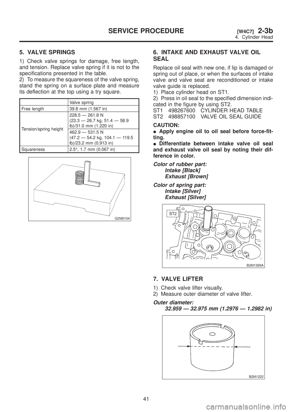
5. VALVE SPRINGS
1) Check valve springs for damage, free length,
and tension. Replace valve spring if it is not to the
specifications presented in the table.
2) To measure the squareness of the valve spring,
stand the spring on a surface plate and measure
its deflection at the top using a try square.
Valve spring
Free length 39.8 mm (1.567 in)
Tension/spring height228.5 Ð 261.8 N
(23.3 Ð 26.7 kg, 51.4 Ð 58.9
lb)/31.0 mm (1.220 in)
462.9 Ð 531.5 N
(47.2 Ð 54.2 kg, 104.1 Ð 119.5
lb)/23.2 mm (0.913 in)
Squareness 2.5É, 1.7 mm (0.067 in)
G2M0154
6. INTAKE AND EXHAUST VALVE OIL
SEAL
Replace oil seal with new one, if lip is damaged or
spring out of place, or when the surfaces of intake
valve and valve seat are reconditioned or intake
valve guide is replaced.
1) Place cylinder head on ST1.
2) Press in oil seal to the specified dimension indi-
cated in the figure by using ST2.
ST1 498267600 CYLINDER HEAD TABLE
ST2 498857100 VALVE OIL SEAL GUIDE
CAUTION:
IApply engine oil to oil seal before force-fit-
ting.
IDifferentiate between intake valve oil seal
and exhaust valve oil seal by noting their dif-
ference in color.
Color of rubber part:
Intake [Black]
Exhaust [Brown]
Color of spring part:
Intake [Silver]
Exhaust [Silver]
B2M1399A
7. VALVE LIFTER
1) Check valve lifter visually.
2) Measure outer diameter of valve lifter.
Outer diameter:
32.959 Ð 32.975 mm (1.2976 Ð 1.2982 in)
B2M1222
41
[W4C7]2-3bSERVICE PROCEDURE
4. Cylinder Head