Page 628 of 1456
15) Install rear sun gear.
NOTE:
Pay attention to the orientation of the rear sun
gear.
B3M1158A
16) Install thrust needle bearing to front planetary
carrier.
NOTE:
Pay attention to the orientation of the thrust needle
bearing.
B3M1174A
17) Install front planetary carrier to low clutch
drum.
B3M1157A
18) Install snap ring to low clutch drum.
B3M1156A
19) Install the needle bearing, and secure with the
snap ring.
B3M1164A
20) Install the one-way clutch, one-way clutch
inner race and plate, and secure with the snap ring.
NOTE:
Set the inner race. Make sure that the forward
clutch is free in the clockwise direction and locked
in the counterclockwise direction, as viewed from
the front of the vehicle.
B3M1175A
97
[W18C0]3-2SERVICE PROCEDURE
18. Low Clutch Drum and Planetary Gear
Page 630 of 1456
4) Measurement of backlash (Selection of washer)
Measure the gear backlash with ST1 and ST2, and
insert ST2 through the access window of the case.
ST1 498247001 MAGNET BASE
ST2 498247100 DIAL GAUGE
NOTE:
Measure the backlash by applying a pinion tooth
between two bevel gear teeth.
Standard value:
0.13 Ð 0.18 mm (0.0051 Ð 0.0071 in)
G3M0491
5) Using ST, install taper roller bearing.
ST 398487700 DRIFT
G3M0492
20. Transfer Clutch
A: DISASSEMBLY
1) Remove the seal ring.
CAUTION:
Be careful not to damage the seal ring.
G3M0493
2) Using a press and ST, remove the ball bearing.
CAUTION:
Do not reuse the bearing.
ST 498077600 REMOVER
G3M0494
3) Remove the snap ring, and take out the pres-
sure plate, drive plates, and driven plates.
G3M0495
99
[W20A0]3-2SERVICE PROCEDURE
20. Transfer Clutch
Page 631 of 1456
4) Measurement of backlash (Selection of washer)
Measure the gear backlash with ST1 and ST2, and
insert ST2 through the access window of the case.
ST1 498247001 MAGNET BASE
ST2 498247100 DIAL GAUGE
NOTE:
Measure the backlash by applying a pinion tooth
between two bevel gear teeth.
Standard value:
0.13 Ð 0.18 mm (0.0051 Ð 0.0071 in)
G3M0491
5) Using ST, install taper roller bearing.
ST 398487700 DRIFT
G3M0492
20. Transfer Clutch
A: DISASSEMBLY
1) Remove the seal ring.
CAUTION:
Be careful not to damage the seal ring.
G3M0493
2) Using a press and ST, remove the ball bearing.
CAUTION:
Do not reuse the bearing.
ST 498077600 REMOVER
G3M0494
3) Remove the snap ring, and take out the pres-
sure plate, drive plates, and driven plates.
G3M0495
99
[W20A0]3-2SERVICE PROCEDURE
20. Transfer Clutch
Page 632 of 1456
4) Remove the snap ring with ST1, ST2 and ST3,
and take out the return spring and transfer clutch
piston seal.
ST1 399893600 PLIERS
ST2 398673600 COMPRESSOR
ST3 398623600 SEAT
B3M1415A
5) Apply compressed air to the rear drive shaft to
remove the piston.
G3M0497
B: INSPECTION
1) Check the drive plate facing for wear and dam-
age.
2) Check the snap ring for wear, return spring for
permanent set and breakage, and return spring for
deformation.
3) Check the lathe cut ring for damage.
C: ASSEMBLY
1) Install the transfer clutch piston.
B3M1400A
2) Install return spring to transfer piston.
B3M1177A
3) Install transfer clutch piston seal.
B3M1401A
4) Install ST to rear drive shaft.
ST 499257300 SNAP RING OUTER GUIDE
B3M1402A
5) Install snap ring to ST.
ST 499257300 SNAP RING OUTER GUIDE
B3M1180A
100
3-2[W20B0]SERVICE PROCEDURE
20. Transfer Clutch
Page 633 of 1456
6) Using ST1 and ST2, install snap ring to rear
drive shaft.
NOTE:
After installing snap ring, remove ST1 and ST2.
ST1 499257300 SNAP RING OUTER GUIDE
ST2 499247400 INSTALLER
B3M1181A
7) Install the driven plates, drive plates, pressure
plate and snap ring.
B3M1182A
8) Apply compressed air to see if the assembled
parts move smoothly.
G3M0502
9) Check the clearance.
NOTE:
Before measuring clearance, place the same thick-
ness of shim on both sides to prevent pressure
plate from tilting.
If the clearance is not within the specified range,
select a proper pressure plate.
Standard value:
0.2 Ð 0.6 mm (0.008 Ð 0.024 in)
Allowable limit:
1.6 mm (0.063 in)
G3M0503
Available pressure plates
Part No. Thickness mm (in)
31593AA151
31593AA161
31593AA171
31593AA1813.3 (0.130)
3.7 (0.146)
4.1 (0.161)
4.5 (0.177)
10) Press-fit the ball bearing with ST.
ST 899580100 INSTALLER
G3M0505
101
[W20C0]3-2SERVICE PROCEDURE
20. Transfer Clutch
Page 920 of 1456

Tightening torque:
18
±5 N´m (1.8±0.5 kg-m, 13.0±3.6 ft-lb)
2) Connect brake pipes to PHV.
Tightening torque:
15+3/þ2N´m (1.5+0.3/þ0.2kg-m, 10.8+2.2/þ1.4ft-lb)
CAUTION:
Confirm that brake pipes are not deformed
and/or damaged. Replace them with new ones
if necessary.
3) Install PHV cable to PHV stay.
CAUTION:
If cable clamp (and clips) is damaged, replace
it with a new one.
4) Connect PHV cable with clips.
NOTE:
Avoid sharp bending of PHV cable as it may cause
breakage.
5) Install PHV cable onto cable bracket on engine.
6) Apply grease to the following points.
IHook portion of return spring
ICable end portion of lever
Grease:
SUNLIGHT 2 (Part No. 003602010)
7) Be sure to bleed air from the system.
CAUTION:
After replacing PHV cable or clutch cable with
new one, operate clutch pedal about 30 times
as a running-in operation prior to adjustment.
D: ADJUSTMENTS
Confirm stopping and starting performances by
activating hill holder on an uphill road of 3É or
higher inclination.
1) If vehicle does not stop;
Tighten adjusting nut of PHV cable.
2) If vehicle does not start properly;
ICase A Ð When hill holder is released later than
engagement of clutch pedal (Engine tends to
stall.):
Loosen adjusting nut gradually until smooth start-
ing is enabled.
ICase B Ð When hill holder is released earlier
than engagement of clutch pedal (Vehicle slips
down slightly.):
Tighten adjusting nut so that hill holder is released
later than engagement of clutch pedal (status in
Case A). Then make adjustment the same as in
Case A.NOTE:
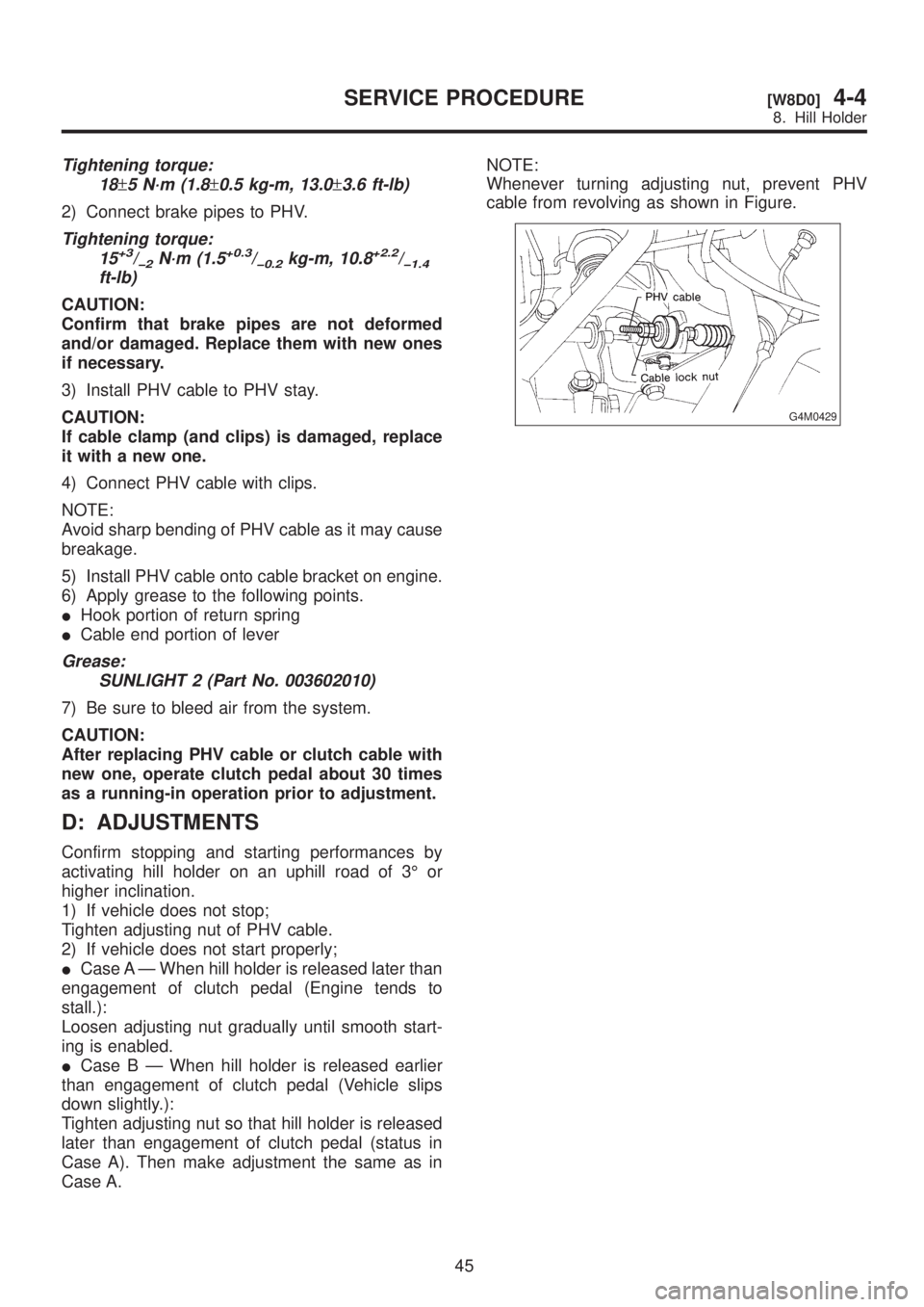
Whenever turning adjusting nut, prevent PHV
cable from revolving as shown in Figure.
G4M0429
45
[W8D0]4-4SERVICE PROCEDURE
8. Hill Holder
Page 935 of 1456

4) Within 0.5 seconds after the ABS warning light
goes out, depress the brake pedal and hold it
immediately after ignition switch is turned to ON.
CAUTION:
Do not depress the clutch pedal.
NOTE:
IWhen the ignition switch is set to on, the brake
pedal must not be depressed.
IEngine must not operate.
5) After completion of ABS sequence control, turn
ignition switch OFF.
2. OPERATIONAL GUIDELINES OF THE
ABS SEQUENCE CONTROL WITH
SELECT MONITOR
NOTE:
IIn the event of any trouble, the sequence con-
trol may not be operative. In such a case, activate
the sequence control, referring to ªOPERATIONAL
GUIDELINES OF THE ABS SEQUENCE CON-
TROL WITH DIAGNOSIS CONNECTORº.
4-4 [W15D1].>
IWhen the diagnosis terminal is connected to the
diagnosis connector, the sequence control will not
operate.
1) Connect select monitor to data link connector
beside driver's seat instrument panel lower cover.
2) Turn ignition switch ON.
3) Turn select monitor switch ON.
4) Put select monitor to {ABS/TCS} mode.
5) When {Function check sequence} is selected,
`ABS sequence control' will start.
6) The message `Press Brake Pedal Firmly' is dis-
played as follows:
(1) When using the brake tester, depress brake
pedal with braking force of 981 N (100 kg, 221
lb).
(2) When using the pressure gauge, depress
brake pedal so as to make the pressure gauge
indicate 3,432 kPa (35 kg/cm
2, 498 psi).
CAUTION:
Do not depress the clutch pedal.
7) When the message ªPress YESº is displayed,
press YES key.
8) Operation points will be displayed on select
monitor.
3. CONDITIONS FOR COMPLETION OF
ABS SEQUENCE CONTROL
When the following conditions develop, the ABS
sequence control stops and ABS operation is
returned to the normal control mode.
1) When the speed of at least one wheel reaches
10 km/h (6 MPH).
2) When terminal No. 3 or No. 6 are separated
from diagnosis terminals. (When select monitor is
not used.)
3) When the brake pedal is released during
sequence control and the braking lamp switch is
set to off.
4) When brake pedal is depressed after ignition
key is turned to ON, and before ABS warning light
goes out. (When select monitor is not used.)
5) When brake pedal is not depressed after igni-
tion key is turned to ON, and within 0.5 seconds
after ABS warning light goes out. (When select
monitor is not used.)
6) After completion of the sequence control.
7) When malfunction is detected. (When select
monitor is used.)
58
4-4[W15D2]SERVICE PROCEDURE
15. ABS Control Module and Hydraulic Control Unit (ABSCM&H/U)
Page 944 of 1456

Trouble and possible cause Corrective action
In the case of the disc brake:
(1) Excessively worn pad or the support Replace the pad or the support.
In the case of the drum brake:
(1) Excessively worn shoe ridge Replace the back plate.
(2) Lack of oil on the shoe ridge surface and anchor Add more grease.
2. Hill Holder
CAUTION:
IDescription in parentheses is a characteris-
tic of hill holder and does not indicate abnor-
mality.
Depressing force required for clutch pedal
equipped to hill holder specifications is 20 to
29 N (2 to 3 kg, 4 to 7 lb) larger than the con-
ventional specifications, which does not con-
stitute abnormality.IWhen vehicle cannot travel (brake cannot be
released) because return spring is broken,
remove adjusting nut, disconnect clutch and
PHV, and then return PHV lever to release the
brake. (Be sure to apply the parking brake
before starting this operation.)
IThe hill holder may not be activated on a
slope of an extremely small inclination.
Trouble and possible cause Corrective action
1. Counterforce of clutch pedal is too strong.
(1) PHV cable is damaged or does not operate properly. Repair or replace.
(2) Lever of PHV is defective. Replace entire PHV assembly.
(3) Clutch system is anomalous. Refer to ªClutch and pedal cable systemº.
2. Vehicle does not stop on uphill road of 3É or higher inclination.
(1) Front side of vehicle is lowered. Refer to ªSuspensionº.
(2) PHV cable is broken. Replace.
(3) Play of clutch is excessive. Adjust.
(4) PHV cable is elongated. Adjust.
(5) Sealing of PHV is poor. Replace entire PHV assembly.
3. Shock is felt when starting.
(1) Poor adjustment of starting performance: Adjust.
(2) When depressing the brake pedal strongly:(The stronger brake pedal depressing force, the later hill
holder releases.)
(3) When starting on flat road after stopping reverse move-
ment:(Because hill holder is activated.)
4. Vehicle slips down when starting.
(1) PHV cable is elongated. Adjust.
(2) Clutch facing is worn out. Adjust or replace.
(3) Bracket (cable) or stay (PHV) is deformed. Repair or replace.
5. Vehicle cannot start after stoppage.
(1) Return spring is fatigued or broken. Replace.
(2) PHV lever won't return. Replace entire PHV assembly.
(3) When intentionally depressing brake pedal strongly:[When the brake pedal is depressed by a force of 1,177 N
(120 kg, 265 lb) or more.]
6. Abnormal sound is generated upon releasing brake pedal when stopping.
(1) Rotor and pad matched with each other due to inadequate
depressing force to brake pedal.(Abnormal sound is not generated when depressing brake
pedal a little stronger.)
7. Abnormal sound is generated when operating clutch pedal.
(1) Grease is inadequate for the hook of return spring and
sliding portion of PHV cable end.Apply grease.
(2) When releasing after maintaining high fluid pressure: (Flowing sound of fluid when releasing high fluid pressure.)
(3) Clutch system is anomalous. Refer to ªClutch and pedal cable systemº.
65
[K200]4-4DIAGNOSTICS
2. Hill Holder