Page 955 of 1456
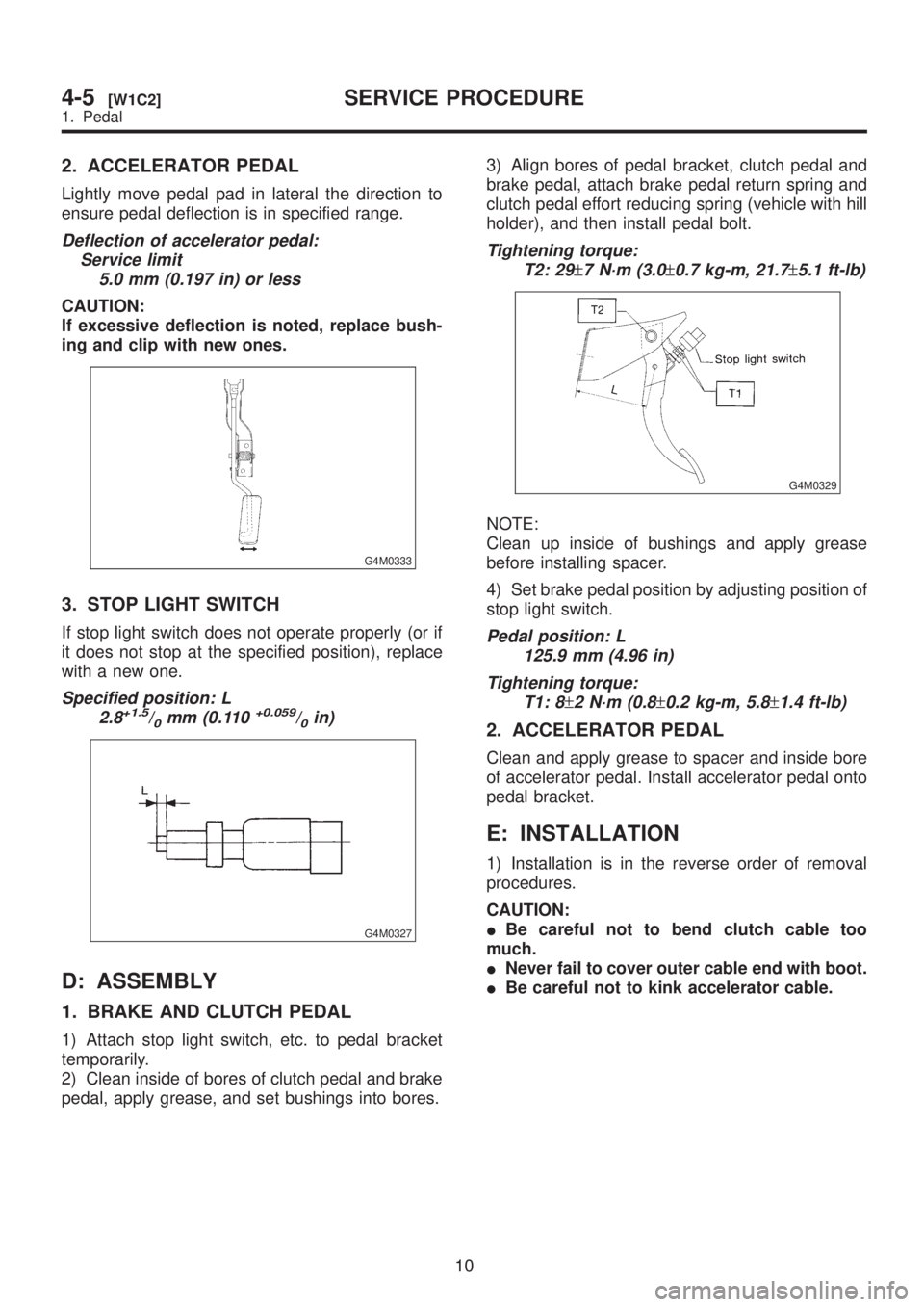
2. ACCELERATOR PEDAL
Lightly move pedal pad in lateral the direction to
ensure pedal deflection is in specified range.
Deflection of accelerator pedal:
Service limit
5.0 mm (0.197 in) or less
CAUTION:
If excessive deflection is noted, replace bush-
ing and clip with new ones.
G4M0333
3. STOP LIGHT SWITCH
If stop light switch does not operate properly (or if
it does not stop at the specified position), replace
with a new one.
Specified position: L
2.8+1.5/0mm (0.110+0.059/0in)
G4M0327
D: ASSEMBLY
1. BRAKE AND CLUTCH PEDAL
1) Attach stop light switch, etc. to pedal bracket
temporarily.
2) Clean inside of bores of clutch pedal and brake
pedal, apply grease, and set bushings into bores.3) Align bores of pedal bracket, clutch pedal and
brake pedal, attach brake pedal return spring and
clutch pedal effort reducing spring (vehicle with hill
holder), and then install pedal bolt.
Tightening torque:
T2: 29
±7 N´m (3.0±0.7 kg-m, 21.7±5.1 ft-lb)
G4M0329
NOTE:
Clean up inside of bushings and apply grease
before installing spacer.
4) Set brake pedal position by adjusting position of
stop light switch.
Pedal position: L
125.9 mm (4.96 in)
Tightening torque:
T1: 8
±2 N´m (0.8±0.2 kg-m, 5.8±1.4 ft-lb)
2. ACCELERATOR PEDAL
Clean and apply grease to spacer and inside bore
of accelerator pedal. Install accelerator pedal onto
pedal bracket.
E: INSTALLATION
1) Installation is in the reverse order of removal
procedures.
CAUTION:
IBe careful not to bend clutch cable too
much.
INever fail to cover outer cable end with boot.
IBe careful not to kink accelerator cable.
10
4-5[W1C2]SERVICE PROCEDURE
1. Pedal
Page 956 of 1456
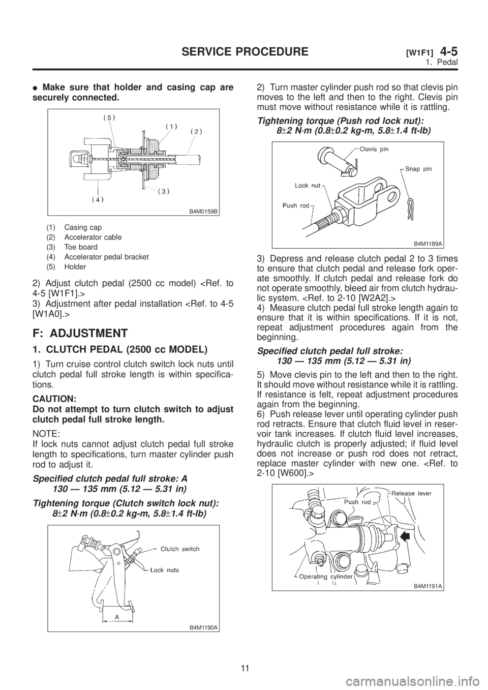
IMake sure that holder and casing cap are
securely connected.
B4M0159B
(1) Casing cap
(2) Accelerator cable
(3) Toe board
(4) Accelerator pedal bracket
(5) Holder
2) Adjust clutch pedal (2500 cc model)
4-5 [W1F1].>
3) Adjustment after pedal installation
[W1A0].>
F: ADJUSTMENT
1. CLUTCH PEDAL (2500 cc MODEL)
1) Turn cruise control clutch switch lock nuts until
clutch pedal full stroke length is within specifica-
tions.
CAUTION:
Do not attempt to turn clutch switch to adjust
clutch pedal full stroke length.
NOTE:
If lock nuts cannot adjust clutch pedal full stroke
length to specifications, turn master cylinder push
rod to adjust it.
Specified clutch pedal full stroke: A
130 Ð 135 mm (5.12 Ð 5.31 in)
Tightening torque (Clutch switch lock nut):
8
±2 N´m (0.8±0.2 kg-m, 5.8±1.4 ft-lb)
B4M1190A
2) Turn master cylinder push rod so that clevis pin
moves to the left and then to the right. Clevis pin
must move without resistance while it is rattling.
Tightening torque (Push rod lock nut):
8
±2 N´m (0.8±0.2 kg-m, 5.8±1.4 ft-lb)
B4M1189A
3) Depress and release clutch pedal 2 to 3 times
to ensure that clutch pedal and release fork oper-
ate smoothly. If clutch pedal and release fork do
not operate smoothly, bleed air from clutch hydrau-
lic system.
4) Measure clutch pedal full stroke length again to
ensure that it is within specifications. If it is not,
repeat adjustment procedures again from the
beginning.
Specified clutch pedal full stroke:
130 Ð 135 mm (5.12 Ð 5.31 in)
5) Move clevis pin to the left and then to the right.
It should move without resistance while it is rattling.
If resistance is felt, repeat adjustment procedures
again from the beginning.
6) Push release lever until operating cylinder push
rod retracts. Ensure that clutch fluid level in reser-
voir tank increases. If clutch fluid level increases,
hydraulic clutch is properly adjusted; if fluid level
does not increase or push rod does not retract,
replace master cylinder with new one.
2-10 [W600].>
B4M1191A
11
[W1F1]4-5SERVICE PROCEDURE
1. Pedal
Page 957 of 1456
2. Clutch Cable
A: REMOVAL
1) Disconnect clutch cable from release lever.
2) Depress clutch pedal to the floor.
3) Remove clutch cable clamp from pedal bracket.
B4M0160A
4) Disconnect clutch cable from pedal bracket and
pedal end.
5) Remove clutch cable from body.
CAUTION:
Before removing clutch cable from toe board,
remove grommet. Slowly remove clutch cable,
being careful not to scratch it.
B: INSTALLATION
1) Clean clutch pedal fitting hole, and apply
grease. Connect clutch cable to clutch pedal.
G4M0332
2) Fit clutch pedal to pedal bolt, and connect
clutch cable to bracket with clamp.
3) Connect clutch cable end to pedal end.
4) Connect clutch cable from release lever.
5) Install grommet to toe board.
6) Adjust after cable installation.
[W1A3].>
12
4-5[W2A0]SERVICE PROCEDURE
2. Clutch Cable
Page 960 of 1456
1. Pedal System and Control Cables
Trouble Corrective action
Excessively worn brake pedal pad Replace.
Failure of clutch and/or accelerator pedals to operate Connect cables correctly.
Stop light switch does not light up. Adjust position of stop light switch.
Stop light switch is not smooth and/or stroke is not correct. Replace.
Insufficient pedal play Adjust pedal play.
Clutch and/or brake pedal free play insufficient Adjust pedal free play.
Maladjustment of brake pedal or booster push rod Inspect and adjust.
Excessively worn and damaged pedal shaft and/or bushing Replace bushing and/or shaft with new one.
15
[K100]4-5DIAGNOSTICS
1. Pedal System and Control Cables
Page 976 of 1456
1. Air Conditioning System
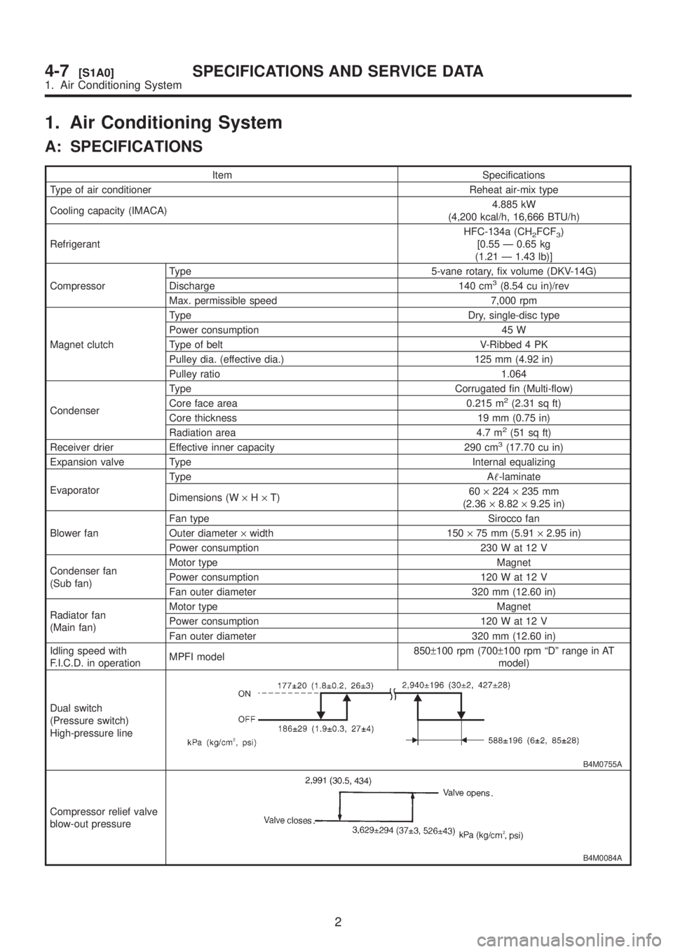
A: SPECIFICATIONS
Item Specifications
Type of air conditioner Reheat air-mix type
Cooling capacity (IMACA)4.885 kW
(4,200 kcal/h, 16,666 BTU/h)
RefrigerantHFC-134a (CH
2FCF3)
[0.55 Ð 0.65 kg
(1.21 Ð 1.43 lb)]
CompressorType 5-vane rotary, fix volume (DKV-14G)
Discharge 140 cm
3(8.54 cu in)/rev
Max. permissible speed 7,000 rpm
Magnet clutchType Dry, single-disc type
Power consumption 45 W
Type of belt V-Ribbed 4 PK
Pulley dia. (effective dia.) 125 mm (4.92 in)
Pulley ratio 1.064
CondenserType Corrugated fin (Multi-flow)
Core face area 0.215 m
2(2.31 sq ft)
Core thickness 19 mm (0.75 in)
Radiation area 4.7 m
2(51 sq ft)
Receiver drier Effective inner capacity 290 cm3(17.70 cu in)
Expansion valve Type Internal equalizing
EvaporatorType A-laminate
Dimensions (W´H´T)60´224´235 mm
(2.36´8.82´9.25 in)
Blower fanFan type Sirocco fan
Outer diameter´width 150´75 mm (5.91´2.95 in)
Power consumption 230 W at 12 V
Condenser fan
(Sub fan)Motor type Magnet
Power consumption 120 W at 12 V
Fan outer diameter 320 mm (12.60 in)
Radiator fan
(Main fan)Motor type Magnet
Power consumption 120 W at 12 V
Fan outer diameter 320 mm (12.60 in)
Idling speed with
F.I.C.D. in operationMPFI model850±100 rpm (700±100 rpm ªDº range in AT
model)
Dual switch
(Pressure switch)
High-pressure line
B4M0755A
Compressor relief valve
blow-out pressure
B4M0084A
2
4-7[S1A0]SPECIFICATIONS AND SERVICE DATA
1. Air Conditioning System
Page 996 of 1456
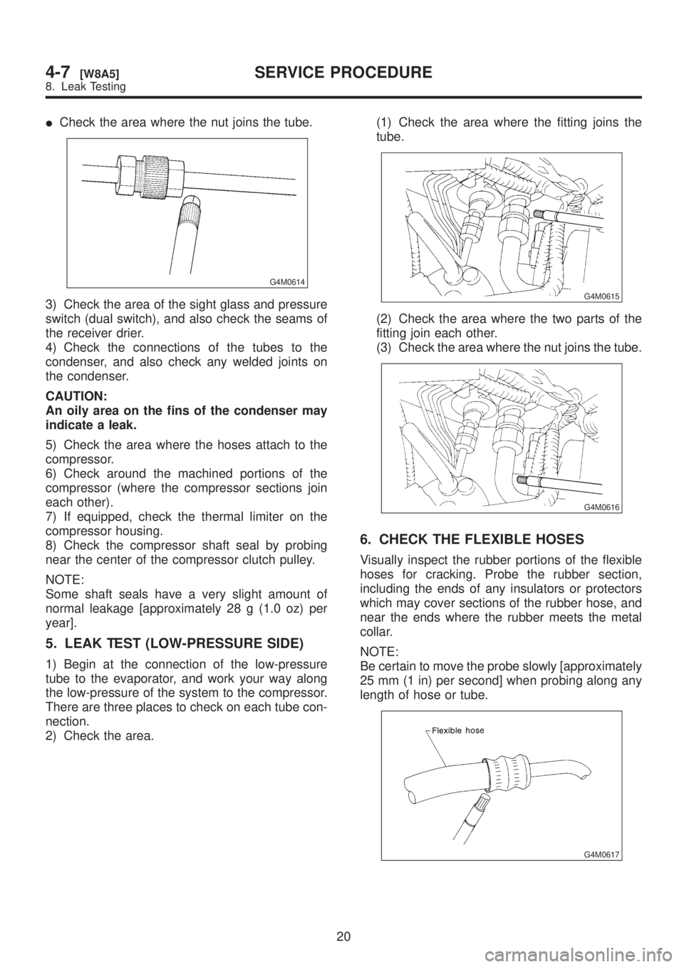
ICheck the area where the nut joins the tube.
G4M0614
3) Check the area of the sight glass and pressure
switch (dual switch), and also check the seams of
the receiver drier.
4) Check the connections of the tubes to the
condenser, and also check any welded joints on
the condenser.
CAUTION:
An oily area on the fins of the condenser may
indicate a leak.
5) Check the area where the hoses attach to the
compressor.
6) Check around the machined portions of the
compressor (where the compressor sections join
each other).
7) If equipped, check the thermal limiter on the
compressor housing.
8) Check the compressor shaft seal by probing
near the center of the compressor clutch pulley.
NOTE:
Some shaft seals have a very slight amount of
normal leakage [approximately 28 g (1.0 oz) per
year].
5. LEAK TEST (LOW-PRESSURE SIDE)
1) Begin at the connection of the low-pressure
tube to the evaporator, and work your way along
the low-pressure of the system to the compressor.
There are three places to check on each tube con-
nection.
2) Check the area.(1) Check the area where the fitting joins the
tube.
G4M0615
(2) Check the area where the two parts of the
fitting join each other.
(3) Check the area where the nut joins the tube.
G4M0616
6. CHECK THE FLEXIBLE HOSES
Visually inspect the rubber portions of the flexible
hoses for cracking. Probe the rubber section,
including the ends of any insulators or protectors
which may cover sections of the rubber hose, and
near the ends where the rubber meets the metal
collar.
NOTE:
Be certain to move the probe slowly [approximately
25 mm (1 in) per second] when probing along any
length of hose or tube.
G4M0617
20
4-7[W8A5]SERVICE PROCEDURE
8. Leak Testing
Page 1001 of 1456
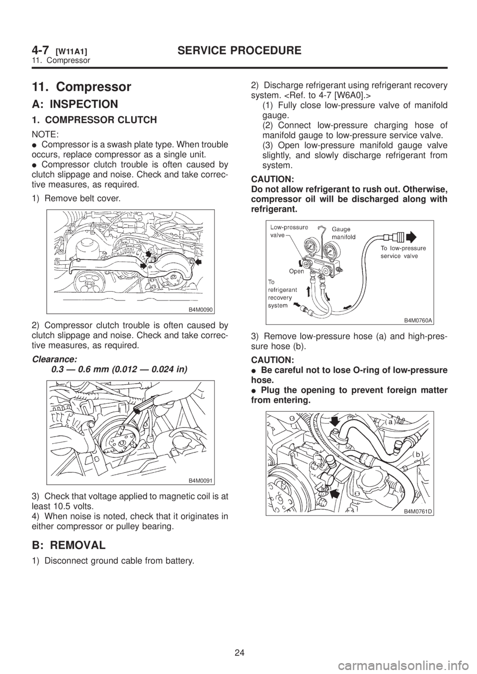
11. Compressor
A: INSPECTION
1. COMPRESSOR CLUTCH
NOTE:
ICompressor is a swash plate type. When trouble
occurs, replace compressor as a single unit.
ICompressor clutch trouble is often caused by
clutch slippage and noise. Check and take correc-
tive measures, as required.
1) Remove belt cover.
B4M0090
2) Compressor clutch trouble is often caused by
clutch slippage and noise. Check and take correc-
tive measures, as required.
Clearance:
0.3 Ð 0.6 mm (0.012 Ð 0.024 in)
B4M0091
3) Check that voltage applied to magnetic coil is at
least 10.5 volts.
4) When noise is noted, check that it originates in
either compressor or pulley bearing.
B: REMOVAL
1) Disconnect ground cable from battery.2) Discharge refrigerant using refrigerant recovery
system.
(1) Fully close low-pressure valve of manifold
gauge.
(2) Connect low-pressure charging hose of
manifold gauge to low-pressure service valve.
(3) Open low-pressure manifold gauge valve
slightly, and slowly discharge refrigerant from
system.
CAUTION:
Do not allow refrigerant to rush out. Otherwise,
compressor oil will be discharged along with
refrigerant.
B4M0760A
3) Remove low-pressure hose (a) and high-pres-
sure hose (b).
CAUTION:
IBe careful not to lose O-ring of low-pressure
hose.
IPlug the opening to prevent foreign matter
from entering.
B4M0761D
24
4-7[W11A1]SERVICE PROCEDURE
11. Compressor
Page 1020 of 1456
5. Compressor Clutch Diagnosis
B4M1105A
40
4-7[K500]DIAGNOSTICS
5. Compressor Clutch Diagnosis