Page 591 of 1456

(1) Using a press and ST1, install the needle
bearing to the inner race.
ST1 398497701 INSTALLER
NOTE:
Use the following ST when removing.
ST 398527700 PULLER ASSY
B3M1409A
(2) Install two seal rings to one-way clutch inner
race.
NOTE:
Apply vaseline to the groove of the inner race and
to the seal ring after installation, so that the seal
ring will not expand.
B3M1100A
(3) Tighten eight socket head bolts from the
rear side of the transmission case.
Tightening torque:
25
±2 N´m (2.5±0.2 kg-m, 18.1±1.4 ft-lb)
CAUTION:
Be sure to tighten evenly.
B3M0958
(4) Install thrust needle bearing.NOTE:
Place transmission case with the front facing up.
12) Installation of the low & reverse brake:
(1) Install dish plate, driven plates, drive plates,
and a retaining plate, and secure with a snap
ring.
NOTE:
Pay attention to the orientation of the dish plate.
B3M1081A
(2) Apply compressed air intermittently to
check for operation.
B3M0957
(3) Check the clearance. (Selection of retaining
plate)
NOTE:
Before measuring clearance, place the same thick-
ness of shim on both sides to prevent retaining
plate from tilting.
Standard value:
0.7 Ð 1.2 mm (0.028 Ð 0.047 in)
Allowable limit:
2.2 mm (0.087 in)
B3M0977
62
3-2[W11C2]SERVICE PROCEDURE
11. Overall Transmission
Page 593 of 1456

19) Install planetary gear and low clutch assembly
to transmission case.
Install carefully while rotating the low clutch and
planetary gear assembly slowly paying special
attention not to damage the seal ring.
B3M1076A
20) Installation of the 2-4 brake:
(1) Install pressure plate, drive plate, driven
plate, retaining plate and snap ring.
B3M1075
(2) Install 2-4 brake oil seal to transmission
case.
NOTE:
Be sure to use a new one.
B3M1102A
(3) After all 2-4 brake component parts have
been installed, blow in air intermittently and con-
firm the operation of the brake.
B3M1103
(4) Measure the clearance between the retain-
ing plate and the snap ring.
NOTE:
Select a retaining plate with a suitable value from
the following table, so that the clearance becomes
the standard value.
Standard value:
0.8 Ð 1.2 mm (0.031 Ð 0.047 in)
Allowable limit:
1.5 mm (0.059 in)
B3M0980
Available retaining plates
Part No. Thickness mm (in)
31567AA610
31567AA620
31567AA630
31567AA640
31567AA650
31567AA6605.6 (0.220)
5.8 (0.228)
6.0 (0.236)
6.2 (0.244)
6.4 (0.252)
6.6 (0.260)
64
3-2[W11C2]SERVICE PROCEDURE
11. Overall Transmission
Page 594 of 1456

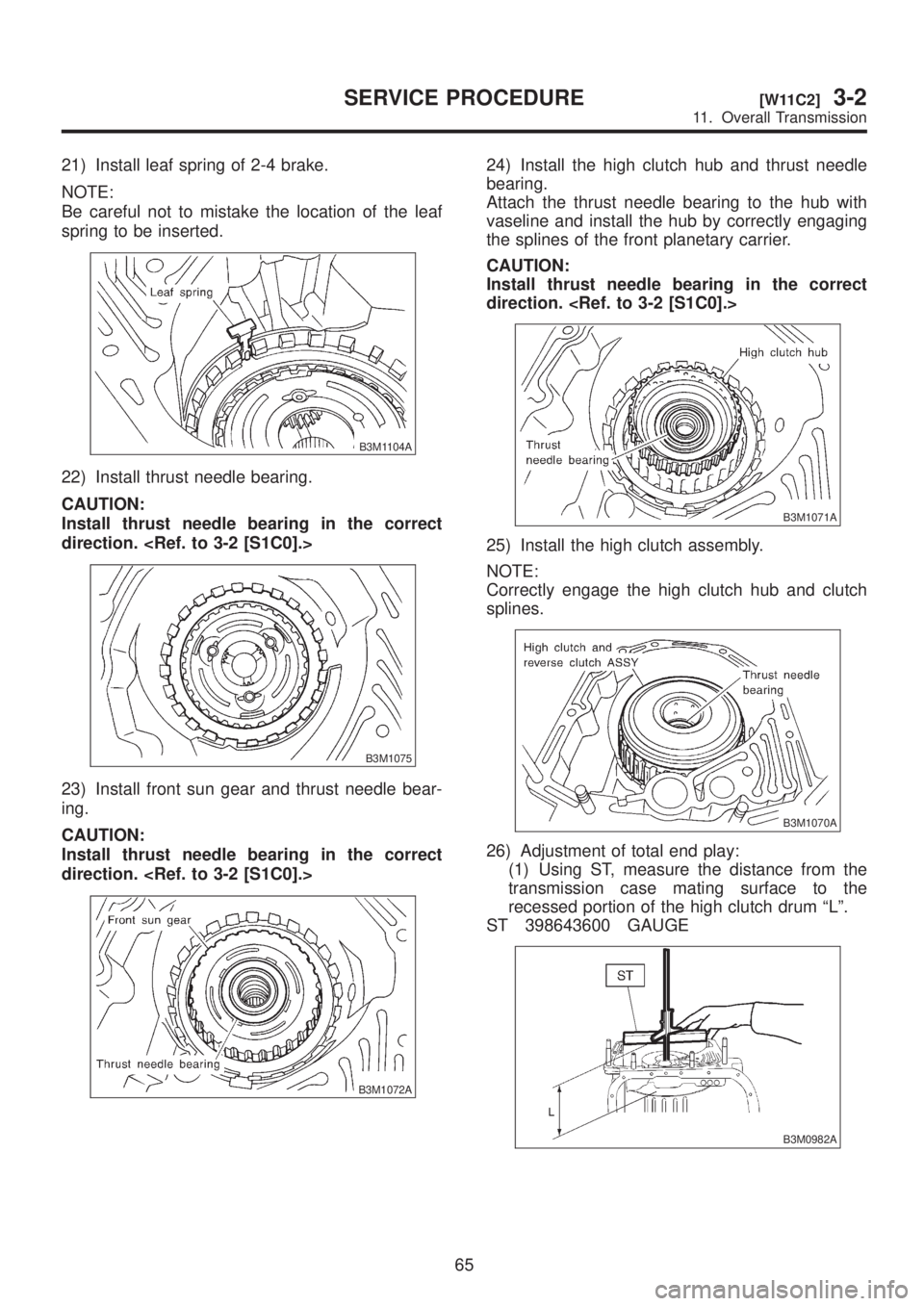
21) Install leaf spring of 2-4 brake.
NOTE:
Be careful not to mistake the location of the leaf
spring to be inserted.
B3M1104A
22) Install thrust needle bearing.
CAUTION:
Install thrust needle bearing in the correct
direction.
B3M1075
23) Install front sun gear and thrust needle bear-
ing.
CAUTION:
Install thrust needle bearing in the correct
direction.
B3M1072A
24) Install the high clutch hub and thrust needle
bearing.
Attach the thrust needle bearing to the hub with
vaseline and install the hub by correctly engaging
the splines of the front planetary carrier.
CAUTION:
Install thrust needle bearing in the correct
direction.
B3M1071A
25) Install the high clutch assembly.
NOTE:
Correctly engage the high clutch hub and clutch
splines.
B3M1070A
26) Adjustment of total end play:
(1) Using ST, measure the distance from the
transmission case mating surface to the
recessed portion of the high clutch drum ªLº.
ST 398643600 GAUGE
B3M0982A
65
[W11C2]3-2SERVICE PROCEDURE
11. Overall Transmission
Page 595 of 1456

(2) Using ST, measure the distance from the oil
pump housing mating surface to the top surface
of the oil pump cover with thrust needle bearing.
ST 398643600 GAUGE
B3M0983A
(3) Calculation of total end play
Select suitable bearing race from among those
listed in this table so that clearance C is in the
0.25 Ð 0.55 mm (0.0098 Ð 0.0217 in) range.
C=(L+G)þ
CClearance between concave portion of high clutch
and end of clutch drum support
LLength from case mating surface to concave por-
tion of high clutch
G Gasket thickness (0.28 mm, 0.0110 in)
Height from housing mating surface to upper sur-
face of clutch drum support
B3M0984A
Thrust needle bearing
Part No. Thickness mm (in)
806528050
806528060
806528070
806528080
806528090
8065281004.1 (0.161)
4.3 (0.169)
4.5 (0.177)
4.7 (0.185)
4.9 (0.193)
5.1 (0.201)
27) Install the oil pump housing assembly.
(1) After completing end play adjustment, insert
the bearing race in the recess of the high clutch.
Attach the thrust needle bearing to the oil pump
cover with vaseline.(2) After correctly installing the gasket to the
case mating surface, carefully install the oil
pump housing assembly. Be careful to avoid hit-
ting the drive pinion against the inside of the
case.
CAUTION:
IBe careful not to damage the seal ring.
IBe sure to use a new gasket.
(3) Install both parts with dowel pins aligned.
Make sure no clearance exists at the mating
surface.
NOTE:
Any clearance suggests a damaged seal ring.
(4) Secure the housing with two nuts.
Tightening torque:
T: 4 1
±3 N´m (4.2±0.3 kg-m, 30.4±2.2 ft-lb)
B3M1068A
3. TORQUE CONVERTER CLUTCH CASE
AND TRANSMISSION CASE
1) Apply proper amount of liquid gasket (THREE
BOND Part No. 1215) to the entire torque con-
verter clutch case mating surface.
NOTE:
Make sure that the rubber seal and seal pipe are
fitted in position.
G3M0394
66
3-2[W11C3]SERVICE PROCEDURE
11. Overall Transmission
Page 596 of 1456

2) Install the torque converter clutch case assem-
bly to the transmission case assembly, and secure
with six bolts and four nuts.
CAUTION:
When installing, be careful not to damage the
torque converter clutch case bushing and oil
seal.
Tightening torque:
41
±3 N´m (4.2±0.3 kg-m, 30.4±2.2 ft-lb)
B3M1055A
4. CONTROL VALVE AND OIL PAN
1) Install and route the transmission harness.
CAUTION:
Be careful not to damage the harness.
B3M1067A
2) Install the control valve assembly.
(1) Set the select lever in range ªNº.(2) Install the control valve by engaging the
manual valve and manual lever, then tighten the
17 bolts.
CAUTION:
Tighten the control valve mounting bolts
evenly.
Tightening torque:
8
±1 N´m (0.8±0.1 kg-m, 5.8±0.7 ft-lb)
B3M1037A
(A) Short bolts
(B) Long bolts
3) Connect all connectors.
B2M2263C
(A) Lock-up duty solenoid (Blue)
(B) Low clutch timing solenoid (Gray)
(C) Line pressure duty solenoid (Red)
(D) Shift solenoid 2 (Yellow)
(E) Shift solenoid 1 (Green)
(F) 2-4 brake timing solenoid (Black)
(G) 2-4 brake duty solenoid (Red)
(H) ATF temperature sensor
4) Install the oil pan.
67
[W11C4]3-2SERVICE PROCEDURE
11. Overall Transmission
Page 597 of 1456
(1) Attach the magnet at the specified position.
B3M1105A
(2) Apply proper amount of liquid gasket
(THREE BOND Part No. 1217B) to the entire oil
pan mating surace.
B3M1040A
(3) Install the oil pan to the transmission case
assembly, and secure with 20 bolts.
NOTE:
Tighten the bolts evenly.
Tightening torque:
4.9
±0.5 N´m (0.50±0.05 kg-m, 3.6±0.4 ft-lb)
B3M1065A
5) Install torque converter turbine speed sensor
and vehicle speed sensor 2 (front).
Tightening torque:
7
±1 N´m (0.7±0.1 kg-m, 5.1±0.7 ft-lb)
B3M1066A
5. EXTENSION SECTION
NOTE:
When installing new oil seal into extension case,
press it with ST.
ST 498057300 INSTALLER
1) Install the transfer pipe to extension case.
B3M1090A
2) Install the transfer clutch assembly to the case.
CAUTION:
Be careful not to damage the seal rings.
NOTE:
Insert the clutch assembly fully into position until
the bearing shoulder bottoms.
B3M1106A
68
3-2[W11C5]SERVICE PROCEDURE
11. Overall Transmission
Page 601 of 1456

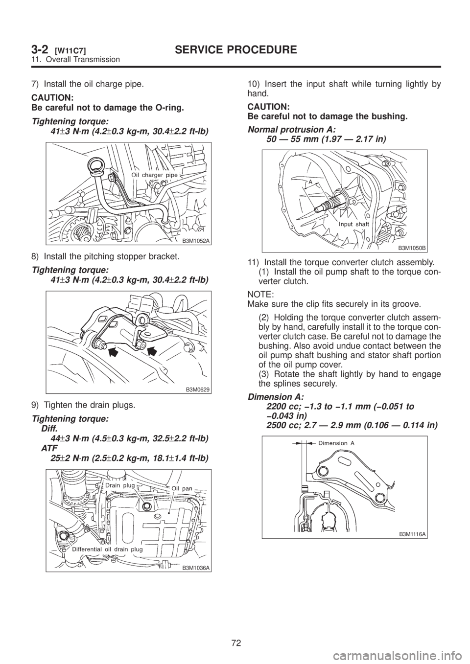
7) Install the oil charge pipe.
CAUTION:
Be careful not to damage the O-ring.
Tightening torque:
41
±3 N´m (4.2±0.3 kg-m, 30.4±2.2 ft-lb)
B3M1052A
8) Install the pitching stopper bracket.
Tightening torque:
41
±3 N´m (4.2±0.3 kg-m, 30.4±2.2 ft-lb)
B3M0629
9) Tighten the drain plugs.
Tightening torque:
Diff.
44
±3 N´m (4.5±0.3 kg-m, 32.5±2.2 ft-lb)
AT F
25
±2 N´m (2.5±0.2 kg-m, 18.1±1.4 ft-lb)
B3M1036A
10) Insert the input shaft while turning lightly by
hand.
CAUTION:
Be careful not to damage the bushing.
Normal protrusion A:
50 Ð 55 mm (1.97 Ð 2.17 in)
B3M1050B
11) Install the torque converter clutch assembly.
(1) Install the oil pump shaft to the torque con-
verter clutch.
NOTE:
Make sure the clip fits securely in its groove.
(2) Holding the torque converter clutch assem-
bly by hand, carefully install it to the torque con-
verter clutch case. Be careful not to damage the
bushing. Also avoid undue contact between the
oil pump shaft bushing and stator shaft portion
of the oil pump cover.
(3) Rotate the shaft lightly by hand to engage
the splines securely.
Dimension A:
2200 cc; þ1.3 to þ1.1 mm (þ0.051 to
þ0.043 in)
2500 cc; 2.7 Ð 2.9 mm (0.106 Ð 0.114 in)
B3M1116A
72
3-2[W11C7]SERVICE PROCEDURE
11. Overall Transmission
Page 605 of 1456

14. Control Valve Body
A: PRECAUTION
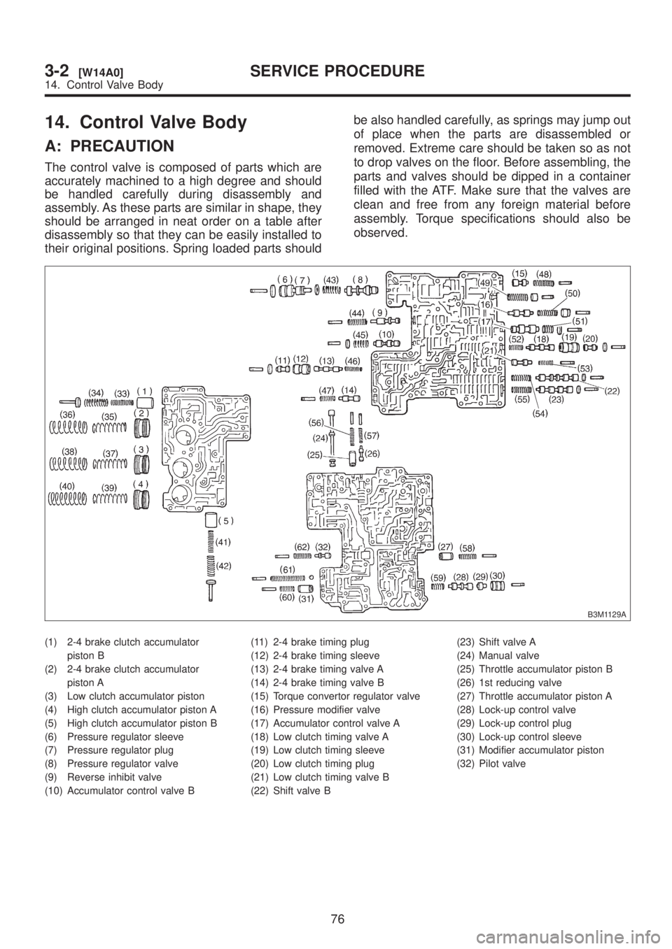
The control valve is composed of parts which are
accurately machined to a high degree and should
be handled carefully during disassembly and
assembly. As these parts are similar in shape, they
should be arranged in neat order on a table after
disassembly so that they can be easily installed to
their original positions. Spring loaded parts shouldbe also handled carefully, as springs may jump out
of place when the parts are disassembled or
removed. Extreme care should be taken so as not
to drop valves on the floor. Before assembling, the
parts and valves should be dipped in a container
filled with the ATF. Make sure that the valves are
clean and free from any foreign material before
assembly. Torque specifications should also be
observed.
B3M1129A
(1) 2-4 brake clutch accumulator
piston B
(2) 2-4 brake clutch accumulator
piston A
(3) Low clutch accumulator piston
(4) High clutch accumulator piston A
(5) High clutch accumulator piston B
(6) Pressure regulator sleeve
(7) Pressure regulator plug
(8) Pressure regulator valve
(9) Reverse inhibit valve
(10) Accumulator control valve B(11) 2-4 brake timing plug
(12) 2-4 brake timing sleeve
(13) 2-4 brake timing valve A
(14) 2-4 brake timing valve B
(15) Torque convertor regulator valve
(16) Pressure modifier valve
(17) Accumulator control valve A
(18) Low clutch timing valve A
(19) Low clutch timing sleeve
(20) Low clutch timing plug
(21) Low clutch timing valve B
(22) Shift valve B(23) Shift valve A
(24) Manual valve
(25) Throttle accumulator piston B
(26) 1st reducing valve
(27) Throttle accumulator piston A
(28) Lock-up control valve
(29) Lock-up control plug
(30) Lock-up control sleeve
(31) Modifier accumulator piston
(32) Pilot valve
76
3-2[W14A0]SERVICE PROCEDURE
14. Control Valve Body