1999 NISSAN PRIMERA light
[x] Cancel search: lightPage 849 of 2267
Emission-related Diagnostic InformationNCEC0031DTC AND 1ST TRIP DTCNCEC0031S01The 1st trip DTC (whose number is the same as the DTC number) is displayed for the latest self-diagnostic
result obtained. If the ECM memory was cleared previously, and the 1st trip DTC did not reoccur, the 1st trip
DTC will not be displayed. If a malfunction is detected during the 1st trip, the 1st trip DTC is stored in the ECM
memory. The MI will not light up (two trip detection logic). If the same malfunction is not detected in the 2nd
trip (meeting the required driving pattern), the 1st trip DTC is cleared from the ECM memory. If the same mal-
function is detected in the 2nd trip, both the 1st trip DTC and DTC are stored in the ECM memory and the MI
lights up. In other words, the DTC is stored in the ECM memory and the MI lights up when the same malfunc-
tion occurs in two consecutive trips. If a 1st trip DTC is stored and a non-diagnostic operation is performed
between the 1st and 2nd trips, only the 1st trip DTC will continue to be stored. For malfunctions that blink or
light up the MI during the 1st trip, the DTC and 1st trip DTC are stored in the ECM memory.
Procedures for clearing the DTC and the 1st trip DTC from the ECM memory are described in ªHOW TO
ERASE EMISSION-RELATED DIAGNOSTIC INFORMATIONº. Refer to EC-SR-56.
For malfunctions in which 1st trip DTCs are displayed, refer to EC-SR-54. These items are required by legal
regulations to continuously monitor the system/component. In addition, the items monitored non-continuously
are also displayed on CONSULT-II.
1st trip DTC is specified in Mode 7 of ISO 15031-5. 1st trip DTC detection occurs without lighting up the MI
and therefore does not warn the driver of a problem. However, 1st trip DTC detection will not prevent the
vehicle from being tested, for example during Inspection/Maintenance (I/M) tests.
When a 1st trip DTC is detected, check, print out or write down and erase (1st trip) DTC and Freeze Frame
data as specified in ªWork Flowº procedure Step II, refer to page EC-SR-82. Then perform ªDTC Confirma-
tion Procedureº or ªOverall Function Checkº to try to duplicate the problem. If the malfunction is duplicated,
the item requires repair.
How to read DTC and 1st Trip DTCNCEC0031S0101DTC and 1st trip DTC can be read by the following methods.
1)
No Tools
The number of blinks of MI in the Diagnostic Test Mode II (Self-Diagnostic Results) Examples: 0340, 1320,
0705, 0750, etc.
These DTCs are controlled by NISSAN.
2)
With CONSULT-II
With GST
CONSULT-II or GST (Generic Scan Tool) Examples: P0340, P1320, P0705, P0750, etc.
These DTCs are prescribed by ISO 15031-6.
(CONSULT-II also displays the malfunctioning component or system.)
I1st trip DTC No. is the same as DTC No.
IOutput of a DTC indicates a malfunction. However, Mode II and GST do not indicate whether the
malfunction is still occurring or has occurred in the past and has returned to normal.
CONSULT-II can identify malfunction status as shown below. Therefore, using CONSULT-II (if avail-
able) is recommended.
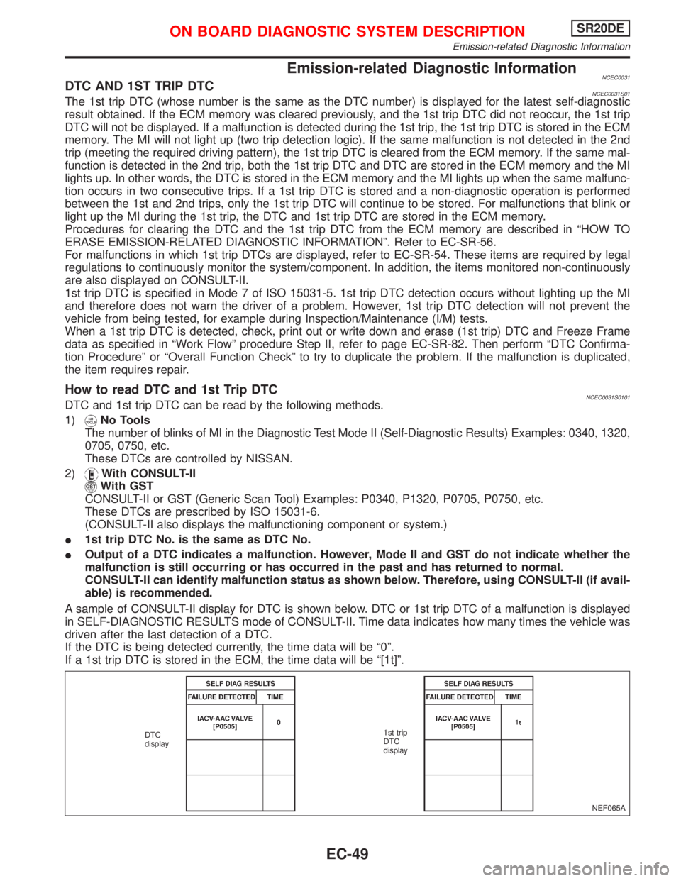
A sample of CONSULT-II display for DTC is shown below. DTC or 1st trip DTC of a malfunction is displayed
in SELF-DIAGNOSTIC RESULTS mode of CONSULT-II. Time data indicates how many times the vehicle was
driven after the last detection of a DTC.
If the DTC is being detected currently, the time data will be ª0º.
If a 1st trip DTC is stored in the ECM, the time data will be ª[1t]º.
NEF065A DTC
display1st trip
DTC
display
ON BOARD DIAGNOSTIC SYSTEM DESCRIPTIONSR20DE
Emission-related Diagnostic Information
EC-49
Page 858 of 2267
How to Erase DTC (No Tools)NCEC0031S0603NOTE:
If the diagnostic trouble code is not for CVT related items (see EC-SR-6), skip step 2.
1. If the ignition switch stays ªONº after repair work, be sure to turn ignition switch ªOFFº once. Wait at least
9 seconds and then turn it ªONº again.
2. Perform ªSELF-DIAGNOSTIC PROCEDURE (Without CONSULT-II)º in AT section titled ªTROUBLE
DIAGNOSISº, ªSelf-diagnosisº. (The engine warm-up step can be skipped when performing the diagnosis
only to erase the DTC.)
3. Change the diagnostic test mode from Mode II to Mode I by using the data link connector. (See EC-SR-
61.)
The emission-related diagnostic information can be erased by changing the diagnostic test mode from Diag-
nostic Test Mode II to Mode I by using the data link connector. (Refer to EC-SR-61.)
NOTE:
IIf the battery is disconnected, the emission-related diagnostic information will be lost after approx.
24 hours.
IErasing the emission-related diagnostic information using CONSULT-II or GST is easier and
quicker than switching the mode using the data link connector.
IThe following data are cleared when the ECM memory is erased.
1) Diagnostic trouble codes
2) 1st trip diagnostic trouble codes
3) Freeze frame data
4) 1st trip freeze frame data
5) System readiness test (SRT) codes
6) Test values
7) Distance traveled while MI is activated
8) Others
Actual work procedures are explained using a DTC as an example. Be careful so that not only the DTC, but
all of the data listed above, are cleared from the ECM memory during work procedures.
Malfunction Indicator (MI)
NATS (NISSAN ANTI-THEFT SYSTEM)
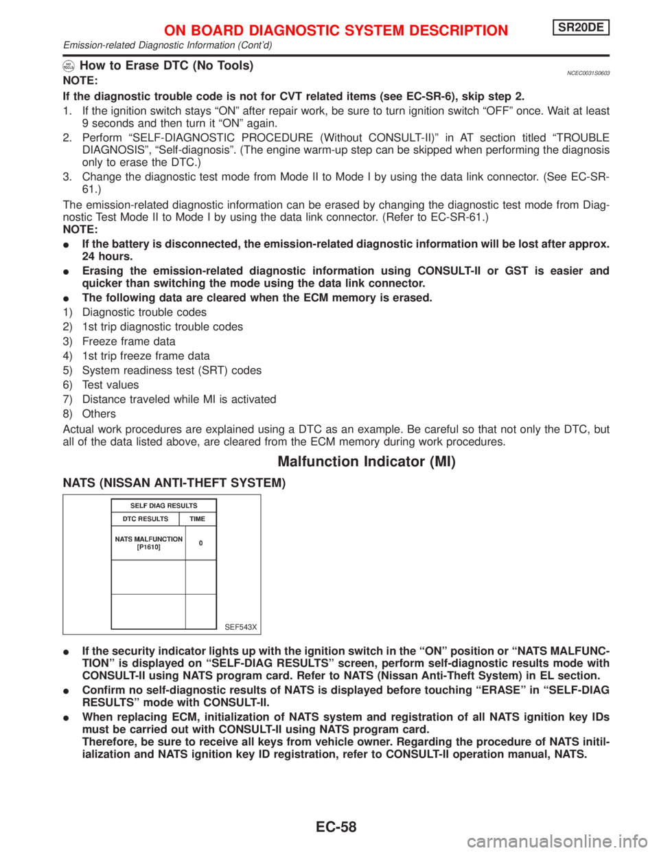
IIf the security indicator lights up with the ignition switch in the ªONº position or ªNATS MALFUNC-
TIONº is displayed on ªSELF-DIAG RESULTSº screen, perform self-diagnostic results mode with
CONSULT-II using NATS program card. Refer to NATS (Nissan Anti-Theft System) in EL section.
IConfirm no self-diagnostic results of NATS is displayed before touching ªERASEº in ªSELF-DIAG
RESULTSº mode with CONSULT-II.
IWhen replacing ECM, initialization of NATS system and registration of all NATS ignition key IDs
must be carried out with CONSULT-II using NATS program card.
Therefore, be sure to receive all keys from vehicle owner. Regarding the procedure of NATS initil-
ialization and NATS ignition key ID registration, refer to CONSULT-II operation manual, NATS.
SEF543X
ON BOARD DIAGNOSTIC SYSTEM DESCRIPTIONSR20DE
Emission-related Diagnostic Information (Cont'd)
EC-58
Page 859 of 2267
DESCRIPTIONNCEC0032
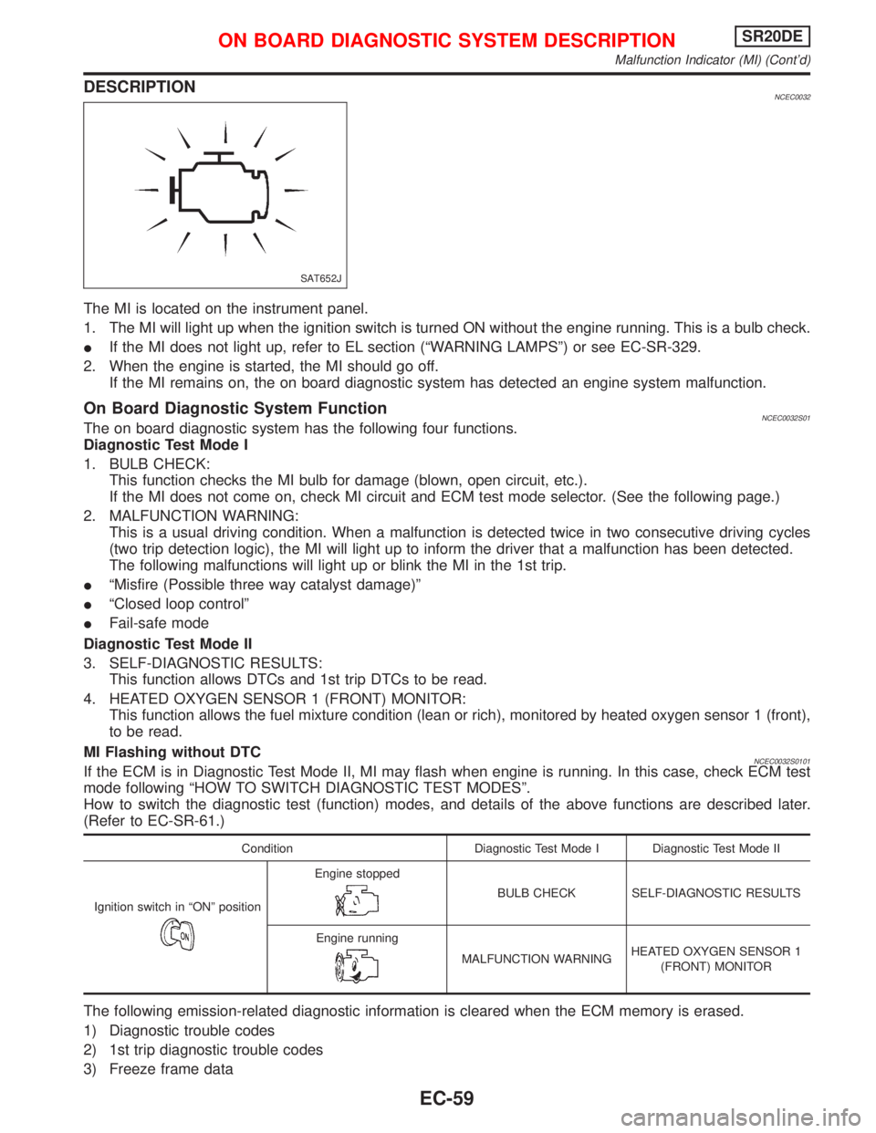
The MI is located on the instrument panel.
1. The MI will light up when the ignition switch is turned ON without the engine running. This is a bulb check.
IIf the MI does not light up, refer to EL section (ªWARNING LAMPSº) or see EC-SR-329.
2. When the engine is started, the MI should go off.
If the MI remains on, the on board diagnostic system has detected an engine system malfunction.
On Board Diagnostic System FunctionNCEC0032S01The on board diagnostic system has the following four functions.
Diagnostic Test Mode I
1. BULB CHECK:
This function checks the MI bulb for damage (blown, open circuit, etc.).
If the MI does not come on, check MI circuit and ECM test mode selector. (See the following page.)
2. MALFUNCTION WARNING:
This is a usual driving condition. When a malfunction is detected twice in two consecutive driving cycles
(two trip detection logic), the MI will light up to inform the driver that a malfunction has been detected.
The following malfunctions will light up or blink the MI in the 1st trip.
IªMisfire (Possible three way catalyst damage)º
IªClosed loop controlº
IFail-safe mode
Diagnostic Test Mode II
3. SELF-DIAGNOSTIC RESULTS:
This function allows DTCs and 1st trip DTCs to be read.
4. HEATED OXYGEN SENSOR 1 (FRONT) MONITOR:
This function allows the fuel mixture condition (lean or rich), monitored by heated oxygen sensor 1 (front),
to be read.
MI Flashing without DTC
NCEC0032S0101If the ECM is in Diagnostic Test Mode II, MI may flash when engine is running. In this case, check ECM test
mode following ªHOW TO SWITCH DIAGNOSTIC TEST MODESº.
How to switch the diagnostic test (function) modes, and details of the above functions are described later.
(Refer to EC-SR-61.)
Condition Diagnostic Test Mode I Diagnostic Test Mode II
Ignition switch in ªONº position
Engine stopped
BULB CHECK SELF-DIAGNOSTIC RESULTS
Engine running
MALFUNCTION WARNINGHEATED OXYGEN SENSOR 1
(FRONT) MONITOR
The following emission-related diagnostic information is cleared when the ECM memory is erased.
1) Diagnostic trouble codes
2) 1st trip diagnostic trouble codes
3) Freeze frame data
SAT652J
ON BOARD DIAGNOSTIC SYSTEM DESCRIPTIONSR20DE
Malfunction Indicator (MI) (Cont'd)
EC-59
Page 864 of 2267
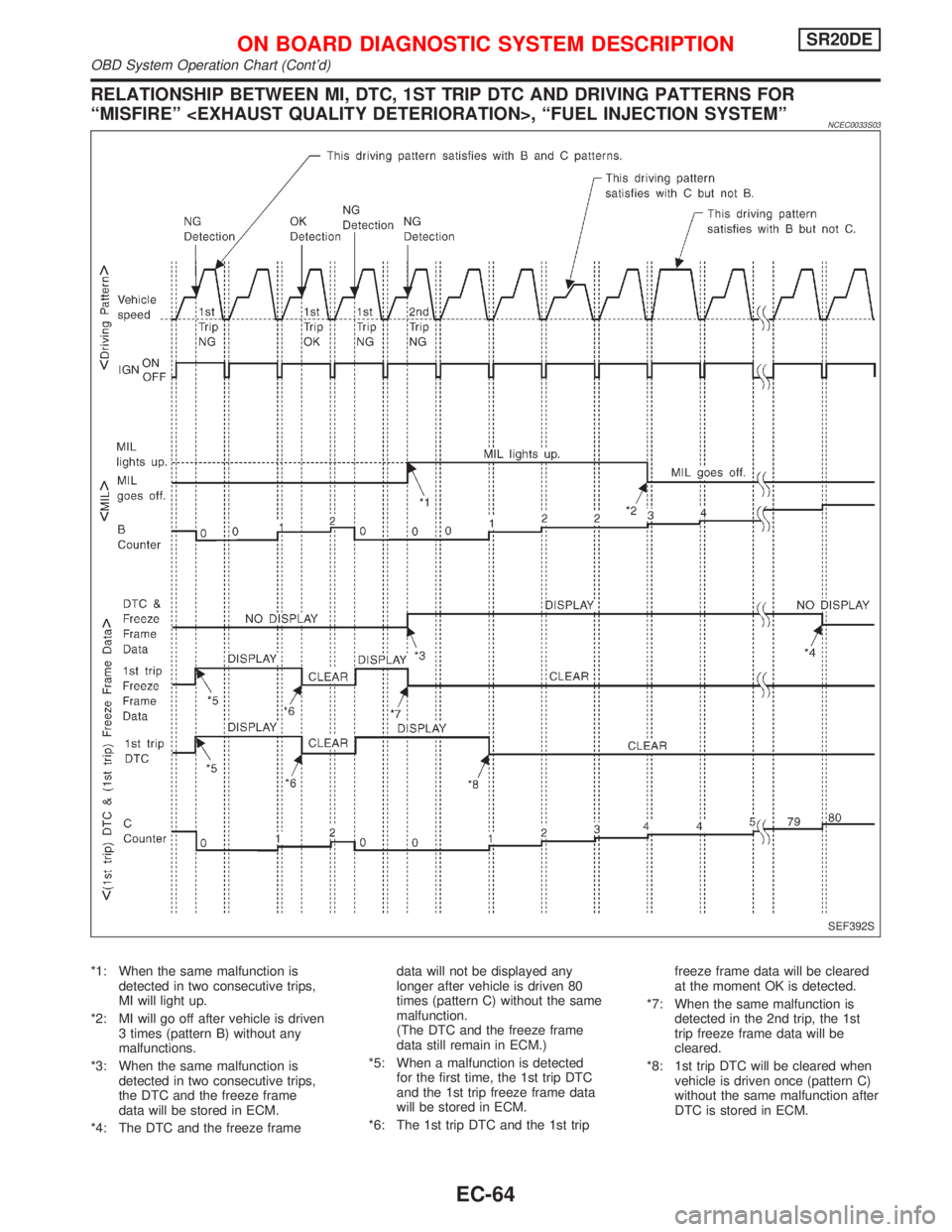
RELATIONSHIP BETWEEN MI, DTC, 1ST TRIP DTC AND DRIVING PATTERNS FOR
ªMISFIREº
NCEC0033S03
*1: When the same malfunction is
detected in two consecutive trips,
MI will light up.
*2: MI will go off after vehicle is driven
3 times (pattern B) without any
malfunctions.
*3: When the same malfunction is
detected in two consecutive trips,
the DTC and the freeze frame
data will be stored in ECM.
*4: The DTC and the freeze framedata will not be displayed any
longer after vehicle is driven 80
times (pattern C) without the same
malfunction.
(The DTC and the freeze frame
data still remain in ECM.)
*5: When a malfunction is detected
for the first time, the 1st trip DTC
and the 1st trip freeze frame data
will be stored in ECM.
*6: The 1st trip DTC and the 1st tripfreeze frame data will be cleared
at the moment OK is detected.
*7: When the same malfunction is
detected in the 2nd trip, the 1st
trip freeze frame data will be
cleared.
*8: 1st trip DTC will be cleared when
vehicle is driven once (pattern C)
without the same malfunction after
DTC is stored in ECM.
SEF392S
ON BOARD DIAGNOSTIC SYSTEM DESCRIPTIONSR20DE
OBD System Operation Chart (Cont'd)
EC-64
Page 866 of 2267
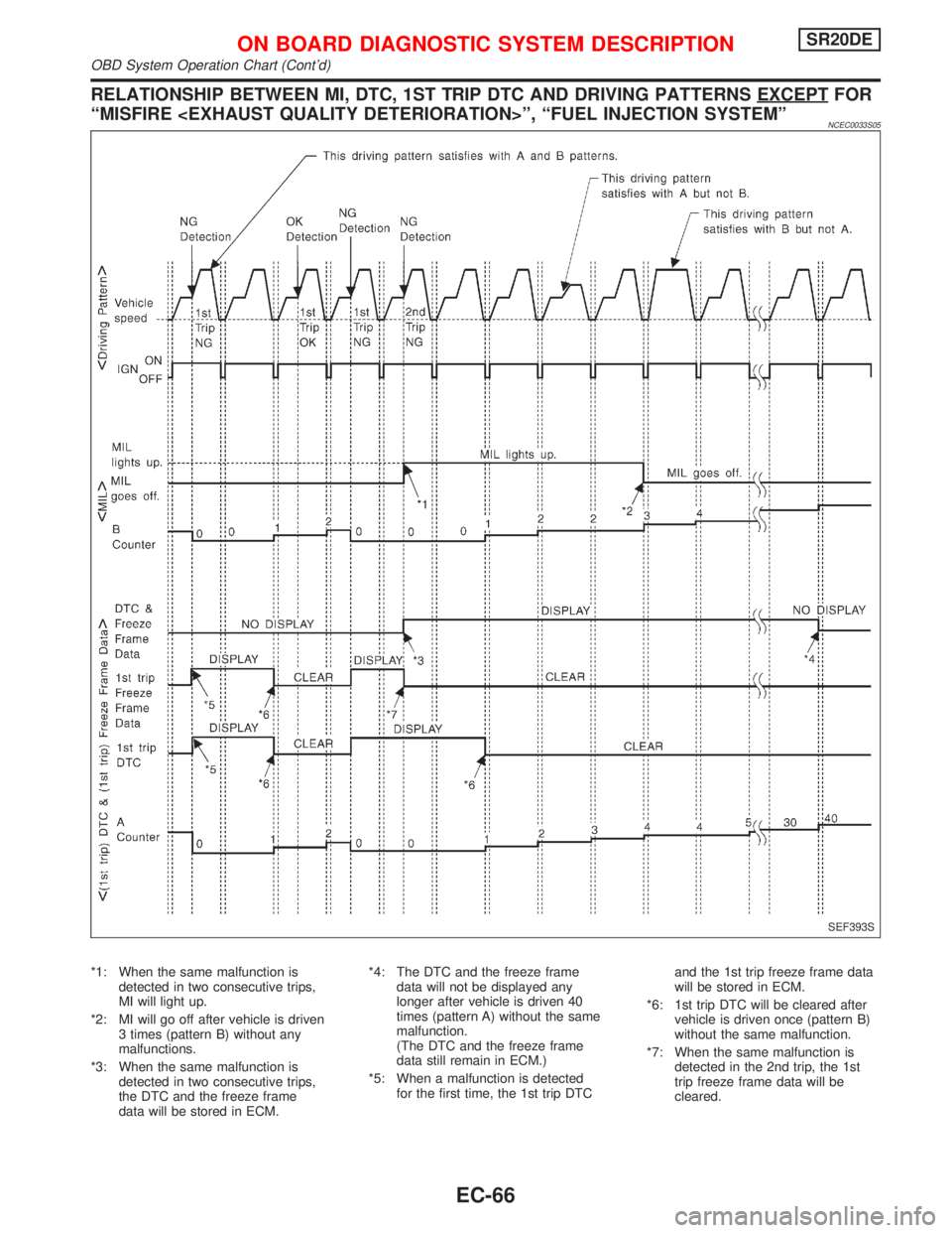
RELATIONSHIP BETWEEN MI, DTC, 1ST TRIP DTC AND DRIVING PATTERNS EXCEPTFOR
ªMISFIRE
NCEC0033S05
*1: When the same malfunction is
detected in two consecutive trips,
MI will light up.
*2: MI will go off after vehicle is driven
3 times (pattern B) without any
malfunctions.
*3: When the same malfunction is
detected in two consecutive trips,
the DTC and the freeze frame
data will be stored in ECM.*4: The DTC and the freeze frame
data will not be displayed any
longer after vehicle is driven 40
times (pattern A) without the same
malfunction.
(The DTC and the freeze frame
data still remain in ECM.)
*5: When a malfunction is detected
for the first time, the 1st trip DTCand the 1st trip freeze frame data
will be stored in ECM.
*6: 1st trip DTC will be cleared after
vehicle is driven once (pattern B)
without the same malfunction.
*7: When the same malfunction is
detected in the 2nd trip, the 1st
trip freeze frame data will be
cleared.
SEF393S
ON BOARD DIAGNOSTIC SYSTEM DESCRIPTIONSR20DE
OBD System Operation Chart (Cont'd)
EC-66
Page 871 of 2267
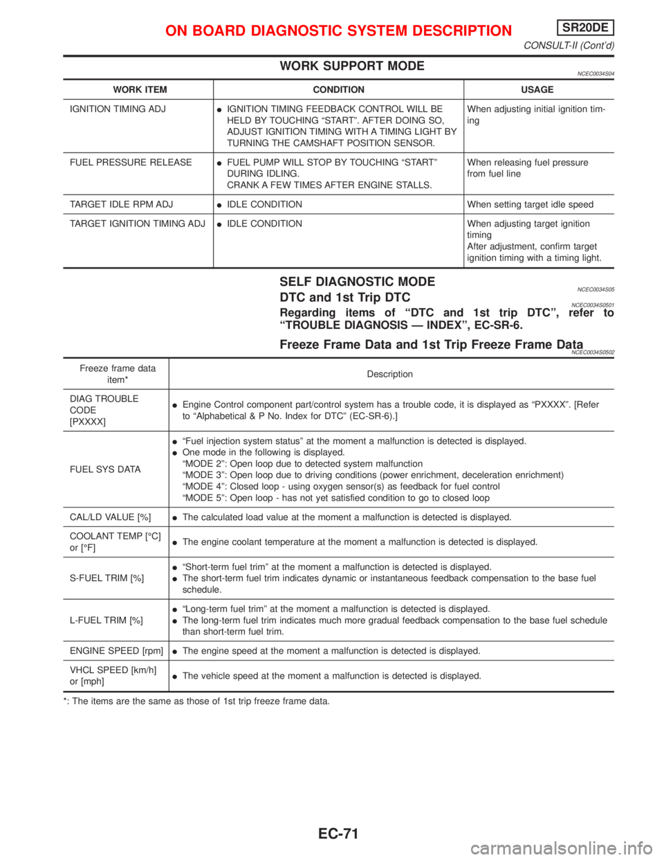
WORK SUPPORT MODENCEC0034S04
WORK ITEM CONDITION USAGE
IGNITION TIMING ADJIIGNITION TIMING FEEDBACK CONTROL WILL BE
HELD BY TOUCHING ªSTARTº. AFTER DOING SO,
ADJUST IGNITION TIMING WITH A TIMING LIGHT BY
TURNING THE CAMSHAFT POSITION SENSOR.When adjusting initial ignition tim-
ing
FUEL PRESSURE RELEASEIFUEL PUMP WILL STOP BY TOUCHING ªSTARTº
DURING IDLING.
CRANK A FEW TIMES AFTER ENGINE STALLS.When releasing fuel pressure
from fuel line
TARGET IDLE RPM ADJIIDLE CONDITION When setting target idle speed
TARGET IGNITION TIMING ADJIIDLE CONDITION When adjusting target ignition
timing
After adjustment, confirm target
ignition timing with a timing light.
SELF DIAGNOSTIC MODENCEC0034S05DTC and 1st Trip DTCNCEC0034S0501Regarding items of ªDTC and 1st trip DTCº, refer to
ªTROUBLE DIAGNOSIS Ð INDEXº, EC-SR-6.
Freeze Frame Data and 1st Trip Freeze Frame DataNCEC0034S0502
Freeze frame data
item*Description
DIAG TROUBLE
CODE
[PXXXX]IEngine Control component part/control system has a trouble code, it is displayed as ªPXXXXº. [Refer
to ªAlphabetical & P No. Index for DTCº (EC-SR-6).]
FUEL SYS DATAIªFuel injection system statusº at the moment a malfunction is detected is displayed.
IOne mode in the following is displayed.
ªMODE 2º: Open loop due to detected system malfunction
ªMODE 3º: Open loop due to driving conditions (power enrichment, deceleration enrichment)
ªMODE 4º: Closed loop - using oxygen sensor(s) as feedback for fuel control
ªMODE 5º: Open loop - has not yet satisfied condition to go to closed loop
CAL/LD VALUE [%]IThe calculated load value at the moment a malfunction is detected is displayed.
COOLANT TEMP [ÉC]
or [ÉF]IThe engine coolant temperature at the moment a malfunction is detected is displayed.
S-FUEL TRIM [%]IªShort-term fuel trimº at the moment a malfunction is detected is displayed.
IThe short-term fuel trim indicates dynamic or instantaneous feedback compensation to the base fuel
schedule.
L-FUEL TRIM [%]IªLong-term fuel trimº at the moment a malfunction is detected is displayed.
IThe long-term fuel trim indicates much more gradual feedback compensation to the base fuel schedule
than short-term fuel trim.
ENGINE SPEED [rpm]IThe engine speed at the moment a malfunction is detected is displayed.
VHCL SPEED [km/h]
or [mph]IThe vehicle speed at the moment a malfunction is detected is displayed.
*: The items are the same as those of 1st trip freeze frame data.
ON BOARD DIAGNOSTIC SYSTEM DESCRIPTIONSR20DE
CONSULT-II (Cont'd)
EC-71
Page 873 of 2267
![NISSAN PRIMERA 1999 Electronic Repair Manual Monitored item [Unit]ECM
input
signalsMain
signalsDescription Remarks
AIR COND SIG
[ON/OFF]qqIIndicates [ON/OFF] condition of the air
conditioner switch as determined by the
air conditioning signal.
P NISSAN PRIMERA 1999 Electronic Repair Manual Monitored item [Unit]ECM
input
signalsMain
signalsDescription Remarks
AIR COND SIG
[ON/OFF]qqIIndicates [ON/OFF] condition of the air
conditioner switch as determined by the
air conditioning signal.
P](/manual-img/5/57377/w960_57377-872.png)
Monitored item [Unit]ECM
input
signalsMain
signalsDescription Remarks
AIR COND SIG
[ON/OFF]qqIIndicates [ON/OFF] condition of the air
conditioner switch as determined by the
air conditioning signal.
P/N POSI SW
[ON/OFF]qqIIndicates [ON/OFF] condition from the
PNP switch signal.
PW/ST SIGNAL
[ON/OFF]qqIIndicates [ON/OFF] condition of the
power steering oil pressure switch deter-
mined by the power steering oil pressure
switch signal.
LOAD SIGNAL
[ON/OFF]qqIIndicates [ON/OFF] condition from the
electrical load signal and/or lighting
switch.
ON ... rear defogger is operating and/or
lighting switch is on.
OFF ... rear defogger is not operating
and lighting switch is not on.
IGNITION SW
[ON/OFF]qIIndicates [ON/OFF] condition from igni-
tion switch.
HEATER FAN SW
[ON/OFF]qIIndicates [ON/OFF] condition from the
heater fan switch.
INJ PULSE -B1
[msec]qIIndicates the actual fuel injection pulse
width compensated by ECM according to
the input signals.IWhen the engine is stopped, a cer-
tain computed value is indicated.
B/FUEL SCHDL
[msec]IªBase fuel scheduleº indicates the fuel
injection pulse width programmed into
ECM, prior to any learned on board cor-
rection.
IGN TIMING [BTDC]qIIndicates the ignition timing computed by
ECM according to the input signals.
IACV-AAC/V [step]qIIndicates the IACV-AAC valve control
value computed by ECM according to
the input signals.
A/F ALPHA -B1 [%]qIIndicates the mean value of the air-fuel
ratio feedback correction factor per
cycle.IWhen the engine is stopped, a cer-
tain value is indicated.
IThis data also includes the data for
the air-fuel ratio learning control.
AIR COND RLY
[ON/OFF]qIIndicates the air conditioner relay control
condition determined by ECM according
to the input signals.
FUEL PUMP RLY
[ON/OFF]qIIndicates the fuel pump relay control
condition determined by ECM according
to the input signals.
COOLING FAN
[HI/LOW/OFF]qIIndicates the control condition of the
cooling fan determined by ECM accord-
ing to the input signals.
HI ... High speed operation
LOW ... Low speed operation
OFF ... Stop
HO2S1 HTR (B1)
[ON/OFF]IIndicates [ON/OFF] condition of heated
oxygen sensor 1 (front) heater deter-
mined by ECM according to the input
signals.
ON BOARD DIAGNOSTIC SYSTEM DESCRIPTIONSR20DE
CONSULT-II (Cont'd)
EC-73
Page 875 of 2267
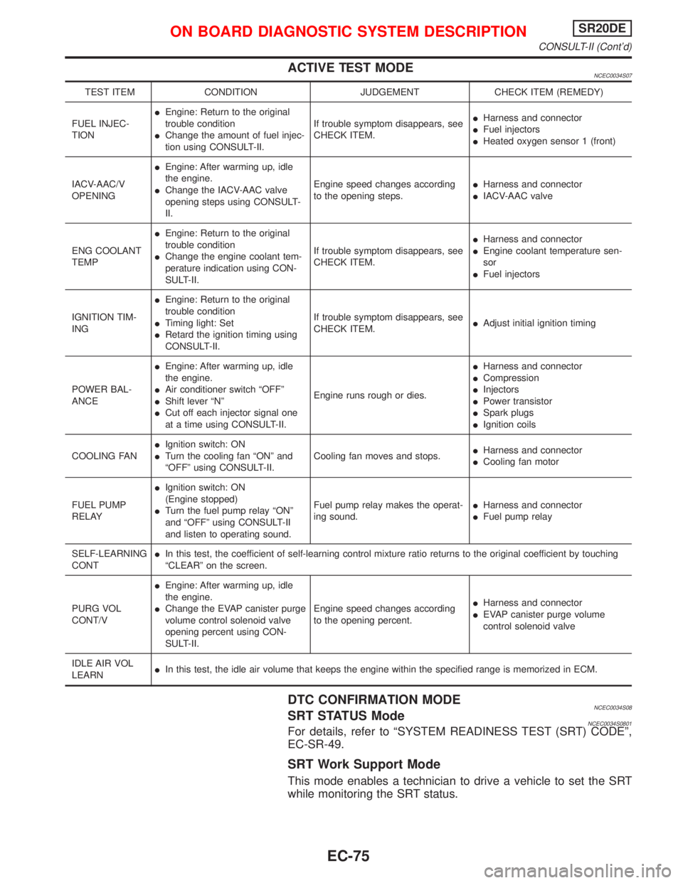
ACTIVE TEST MODENCEC0034S07
TEST ITEM CONDITION JUDGEMENT CHECK ITEM (REMEDY)
FUEL INJEC-
TIONIEngine: Return to the original
trouble condition
IChange the amount of fuel injec-
tion using CONSULT-II.If trouble symptom disappears, see
CHECK ITEM.IHarness and connector
IFuel injectors
IHeated oxygen sensor 1 (front)
IACV-AAC/V
OPENINGIEngine: After warming up, idle
the engine.
IChange the IACV-AAC valve
opening steps using CONSULT-
II.Engine speed changes according
to the opening steps.IHarness and connector
IIACV-AAC valve
ENG COOLANT
TEMPIEngine: Return to the original
trouble condition
IChange the engine coolant tem-
perature indication using CON-
SULT-II.If trouble symptom disappears, see
CHECK ITEM.IHarness and connector
IEngine coolant temperature sen-
sor
IFuel injectors
IGNITION TIM-
INGIEngine: Return to the original
trouble condition
ITiming light: Set
IRetard the ignition timing using
CONSULT-II.If trouble symptom disappears, see
CHECK ITEM.IAdjust initial ignition timing
POWER BAL-
ANCEIEngine: After warming up, idle
the engine.
IAir conditioner switch ªOFFº
IShift lever ªNº
ICut off each injector signal one
at a time using CONSULT-II.Engine runs rough or dies.IHarness and connector
ICompression
IInjectors
IPower transistor
ISpark plugs
IIgnition coils
COOLING FANIIgnition switch: ON
ITurn the cooling fan ªONº and
ªOFFº using CONSULT-II.Cooling fan moves and stops.IHarness and connector
ICooling fan motor
FUEL PUMP
RELAYIIgnition switch: ON
(Engine stopped)
ITurn the fuel pump relay ªONº
and ªOFFº using CONSULT-II
and listen to operating sound.Fuel pump relay makes the operat-
ing sound.IHarness and connector
IFuel pump relay
SELF-LEARNING
CONTIIn this test, the coefficient of self-learning control mixture ratio returns to the original coefficient by touching
ªCLEARº on the screen.
PURG VOL
CONT/VIEngine: After warming up, idle
the engine.
IChange the EVAP canister purge
volume control solenoid valve
opening percent using CON-
SULT-II.Engine speed changes according
to the opening percent.IHarness and connector
IEVAP canister purge volume
control solenoid valve
IDLE AIR VOL
LEARNIIn this test, the idle air volume that keeps the engine within the specified range is memorized in ECM.
DTC CONFIRMATION MODENCEC0034S08SRT STATUS ModeNCEC0034S0801For details, refer to ªSYSTEM READINESS TEST (SRT) CODEº,
EC-SR-49.
SRT Work Support Mode
This mode enables a technician to drive a vehicle to set the SRT
while monitoring the SRT status.
ON BOARD DIAGNOSTIC SYSTEM DESCRIPTIONSR20DE
CONSULT-II (Cont'd)
EC-75