Page 1730 of 2267
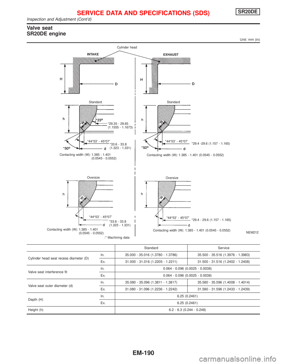
Valve seat
SR20DE engine
Unit: mm (in)
NEM212
Standard Service
Cylinder head seat recess diameter (D)In. 35.000 - 35.016 (1.3780 - 1.3786) 35.500 - 35.516 (1.3976 - 1.3983)
Ex. 31.000 - 31.016 (1.2205 - 1.2211) 31.500 - 31.516 (1.2402 - 1.2408)
Valve seat interference fitIn. 0.064 - 0.096 (0.0025 - 0.0038)
Ex. 0.064 - 0.096 (0.0025 - 0.0038)
Valve seat outer diameter (d)In. 35.080 - 35.096 (1.3811 - 1.3817) 35.580 - 35.596 (1.4008 - 1.4014)
Ex. 31.080 - 31.096 (1.2236 - 1.2242) 31.580 - 31.596 (1.2433 - 1.2439)
Depth (H)In. 6.25 (0.2461)
Ex. 6.25 (0.2461)
Height (h)6.2 - 6.3 (0.244 - 0.248)
INTAKECylinder head
EXHAUST
Standard Standard
*29.35 - 29.65
(1.1555 - 1.1673)
*44É53¢- 45É07¢
*33.6 - 33.8
(1.323 - 1.331)
Contacting width (W): 1.385 - 1.401
(0.0545 - 0.0552)*44É53¢- 45É07¢
*29.4 -29.6 (1.157 - 1.165)
Contacting width (W): 1.385 - 1.401 (0.0545 - 0.0552)
Oversize
Oversize
*44É53¢- 45É07¢
*33.6 - 33.8
(1.323 - 1.331)
Contacting width (W): 1.385 - 1.401
(0.0545 - 0.0552)
:* Machining data*44É53¢- 45É07¢
*29.4 - 29.6 (1.157 - 1.165)
Contacting width (W): 1.385 - 1.401 (0.0545 - 0.0552)
SERVICE DATA AND SPECIFICATIONS (SDS)SR20DE
Inspection and Adjustment (Cont'd)
EM-190
Page 1732 of 2267
CAMSHAFT AND CAMSHAFT BEARING
Unit: mm (in)
Standard Limit
Camshaft journal to
bearing clearance0.030 - 0.071
(0.0012 - 0.0028)0.15 (0.0059)
Inner diameter of
camshaft bearing28.000 - 28.021
(1.1024 - 1.1032)Ð
Outer diameter of
camshaft journal27.950 - 27.970
(1.1004 - 1.1012)Ð
Camshaft runout [TIR*]Less than
0.02 (0.0008)0.1 (0.004)
Camshaft sprocket
runout [TIR*]Less than
0.25 (0.0098)Ð
Camshaft end play0.055 - 0.139
(0.0022 - 0.0055)0.20 (0.0079)
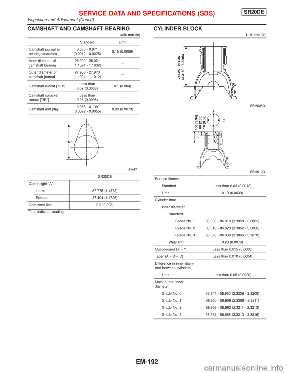
EM671
SR20DE
Cam height ªAº
Intake 37.775 (1.4872)
Exhaust 37.404 (1.4726)
Cam wear limit 0.2 (0.008)
*Total indicator reading
CYLINDER BLOCK
Unit: mm (in)
SEM008D
SEM010D
211.25 - 211.35
(8.3169 - 8.3208)
100 (3.94)
60 (2.36)
10 (0.39)
Surface flatness
Standard Less than 0.03 (0.0012)
Limit 0.10 (0.0039)
Cylinder bore
Inner diameter
Standard
Grade No. 1 86.000 - 86.010 (3.3858 - 3.3862)
Grade No. 2 86.010 - 86.020 (3.3862 - 3.3866)
Grade No. 3 86.020 - 86.030 (3.3866 - 3.3870)
Wear limit 0.20 (0.0079)
Out-of-round (X þ Y) Less than 0.015 (0.0006)
Taper (AþBþC)Less than 0.010 (0.0004)
Difference in inner diam-
eter between cylinders
Limit Less than 0.05 (0.0020)
Main journal inner
diameter
Grade No. 0 58.944 - 58.950 (2.3206 - 2.3209)
Grade No. 1 58.950 - 58.956 (2.3209 - 2.3211)
Grade No. 2 58.956 - 58.962 (2.3211 - 2.3213)
Grade No. 3 58.962 - 58.968 (2.3213 - 2.3216)
SERVICE DATA AND SPECIFICATIONS (SDS)SR20DE
Inspection and Adjustment (Cont'd)
EM-192
Page 1736 of 2267
General Specifications
Cylinder arrangement In-line 4
Displacement cm
3(cu in) 1,974 (120.45)
Bore and stroke mm (in) 84.5´88.0 (3.329´3.465)
Valve arrangement OHC
Firing order 1-3-4-2
Number of piston rings
Compression 2
Oil 1
Number of main bearing 5
Compression ratio 22.2
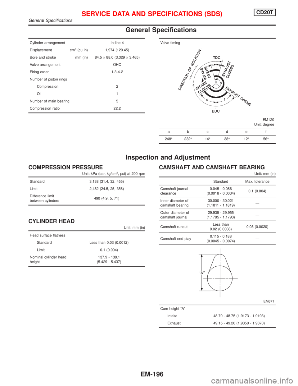
Valve timing
EM120
Unit: degree
abcde f
248É 232É 14É 38É 12É 56É
Inspection and Adjustment
COMPRESSION PRESSURE
Unit: kPa (bar, kg/cm2, psi) at 200 rpm
Standard 3,138 (31.4, 32, 455)
Limit 2,452 (24.5, 25, 356)
Difference limit
between cylinders490 (4.9, 5, 71)
CYLINDER HEAD
Unit: mm (in)
Head surface flatness
Standard Less than 0.03 (0.0012)
Limit 0.1 (0.004)
Nominal cylinder head
height137.9 - 138.1
(5.429 - 5.437)
CAMSHAFT AND CAMSHAFT BEARING
Unit: mm (in)
Standard Max. tolerance
Camshaft journal
clearance0.045 - 0.086
(0.0018 - 0.0034)0.1 (0.004)
Inner diameter of
camshaft bearing30.000 - 30.021
(1.1811 - 1.1819)Ð
Outer diameter of
camshaft journal29.935 - 29.955
(1.1785 - 1.1793)Ð
Camshaft runoutLess than
0.02 (0.0008)0.05 (0.0020)
Camshaft end play0.115 - 0.188
(0.0045 - 0.0074)Ð
EM671
Cam height ªAº
Intake 48.70 - 48.75 (1.9173 - 1.9193)
Exhaust 49.15 - 49.20 (1.9350 - 1.9370)
SERVICE DATA AND SPECIFICATIONS (SDS)CD20T
General Specifications
EM-196
Page 1737 of 2267
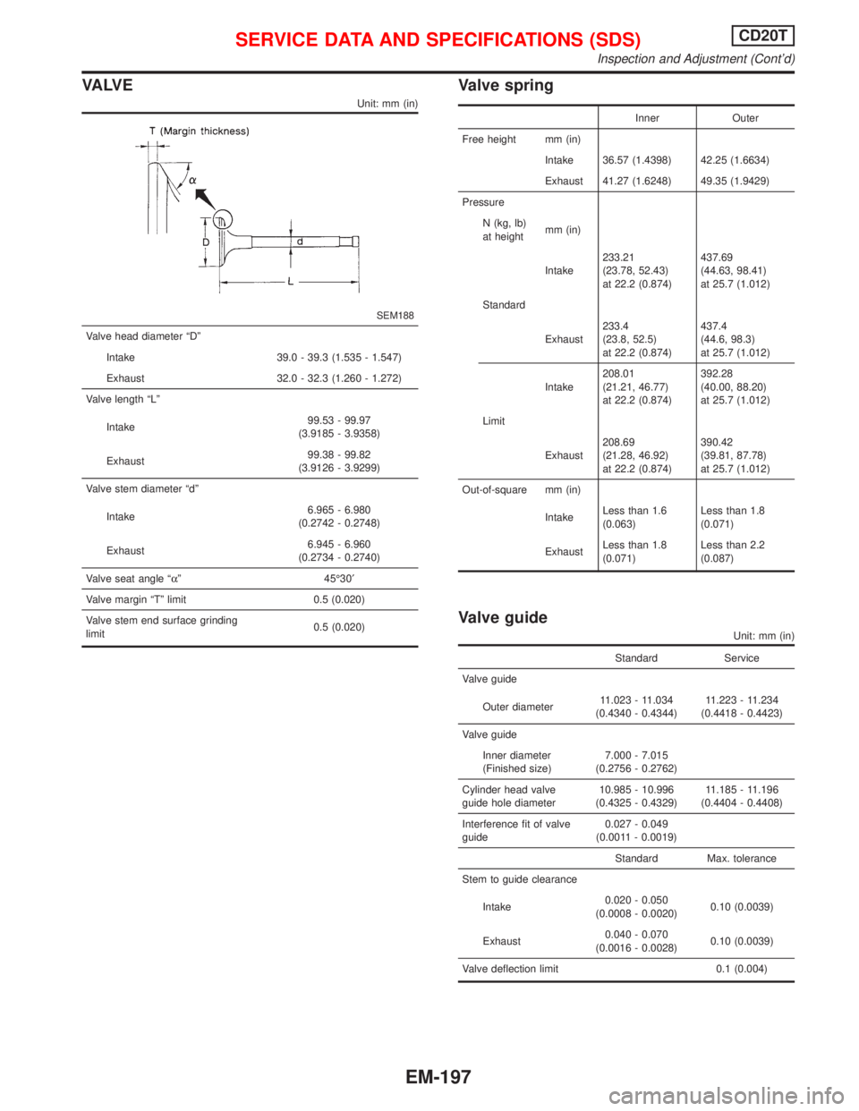
VA LV E
Unit: mm (in)
SEM188
Valve head diameter ªDº
Intake 39.0 - 39.3 (1.535 - 1.547)
Exhaust 32.0 - 32.3 (1.260 - 1.272)
Valve length ªLº
Intake99.53 - 99.97
(3.9185 - 3.9358)
Exhaust99.38 - 99.82
(3.9126 - 3.9299)
Valve stem diameter ªdº
Intake6.965 - 6.980
(0.2742 - 0.2748)
Exhaust6.945 - 6.960
(0.2734 - 0.2740)
Valve seat angle ªaº 45É30¢
Valve margin ªTº limit 0.5 (0.020)
Valve stem end surface grinding
limit0.5 (0.020)
Valve spring
Inner Outer
Free height mm (in)
Intake 36.57 (1.4398) 42.25 (1.6634)
Exhaust 41.27 (1.6248) 49.35 (1.9429)
Pressure
N (kg, lb)
at heightmm (in)
Intake233.21
(23.78, 52.43)
at 22.2 (0.874)437.69
(44.63, 98.41)
at 25.7 (1.012)
Standard
Exhaust233.4
(23.8, 52.5)
at 22.2 (0.874)437.4
(44.6, 98.3)
at 25.7 (1.012)
Intake208.01
(21.21, 46.77)
at 22.2 (0.874)392.28
(40.00, 88.20)
at 25.7 (1.012)
Limit
Exhaust208.69
(21.28, 46.92)
at 22.2 (0.874)390.42
(39.81, 87.78)
at 25.7 (1.012)
Out-of-square mm (in)
IntakeLess than 1.6
(0.063)Less than 1.8
(0.071)
ExhaustLess than 1.8
(0.071)Less than 2.2
(0.087)
Valve guide
Unit: mm (in)
Standard Service
Valve guide
Outer diameter11.023 - 11.034
(0.4340 - 0.4344)11.223 - 11.234
(0.4418 - 0.4423)
Valve guide
Inner diameter
(Finished size)7.000 - 7.015
(0.2756 - 0.2762)
Cylinder head valve
guide hole diameter10.985 - 10.996
(0.4325 - 0.4329)11.185 - 11.196
(0.4404 - 0.4408)
Interference fit of valve
guide0.027 - 0.049
(0.0011 - 0.0019)
Standard Max. tolerance
Stem to guide clearance
Intake0.020 - 0.050
(0.0008 - 0.0020)0.10 (0.0039)
Exhaust0.040 - 0.070
(0.0016 - 0.0028)0.10 (0.0039)
Valve deflection limit 0.1 (0.004)
SERVICE DATA AND SPECIFICATIONS (SDS)CD20T
Inspection and Adjustment (Cont'd)
EM-197
Page 1749 of 2267
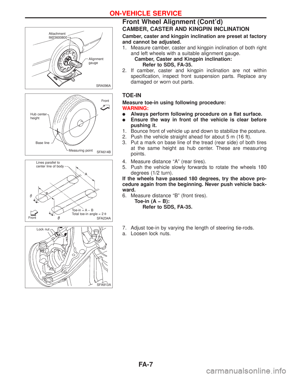
CAMBER, CASTER AND KINGPIN INCLINATION
Camber, caster and kingpin inclination are preset at factory
and cannot be adjusted.
1. Measure camber, caster and kingpin inclination of both right
and left wheels with a suitable alignment gauge.
Camber, Caster and Kingpin inclination:
Refer to SDS, FA-35.
2. If camber, caster and kingpin inclination are not within
specification, inspect front suspension parts. Replace any
damaged or worn out parts.
TOE-IN
Measure toe-in using following procedure:
WARNING:
lAlways perform following procedure on a flat surface.
lEnsure the way in front of the vehicle is clear before
pushing it.
1. Bounce front of vehicle up and down to stabilize the posture.
2. Push the vehicle straight ahead for about 5 m (16 ft).
3. Put a mark on base line of the tread (rear side) of both tires
at the same height as hub center. These are measuring
points.
4. Measure distance ªAº (rear tires).
5. Push the vehicle slowly forwards to rotate the wheels 180
degrees (1/2 turn).
If the wheels have passed 180 degrees, try the above pro-
cedure again from the beginning. Never push vehicle back-
ward.
6. Measure distance ªBº (front tires).
Toe-in (A þ B):
Refer to SDS, FA-35.
7. Adjust toe-in by varying the length of steering tie-rods.
a. Loosen lock nuts.
SRA096A Attachment
IM23600800
Alignment
gauge
SFA614B Hub center
height
Base line
Measuring pointFront
SFA234A FrontLines parallel to
center line of body
Toe-in = A þ B
Total toe-in angle = 2q
.SFA913A Lock nut
ON-VEHICLE SERVICE
Front Wheel Alignment (Cont'd)
FA-7
Page 1840 of 2267
Dimensions
Unit: mm (in)
H/B & Sedan Wagon
Overall length 4522 (178.03) 4566 (179.76)
Overall width 1715 (67.52) *1 1715 (67.52) *1
Overall height 1410 (55.51) *2 1410 (55.51) *2
Front tread 1470 (57.87) 1470 (57.87)
Rear tread 1450 (57.09) 1450 (57.09)
Wheelbase 2600 (102.36) 2600 (102.36)
*1: Without mirrors.
*2: Without roof mounted antenna.
Wheels and Tires
Road
wheelSteel 15 x 6J
ÐÐÐ
Offset
mm (in)45 (1.77)
Aluminum
Ð15x6J 15x6J 16x7J
Offset
mm (in)45 (1.77) 45 (1.77) 45 (1.77)
Tire
sizeConven-
tional185/65HR15 195/60VR15 195/60R15 205/50R16
SpareConven-
tionalConven-
tionalConven-
tional185/65
HR15
IDENTIFICATION INFORMATION
GI-45
Page 2080 of 2267
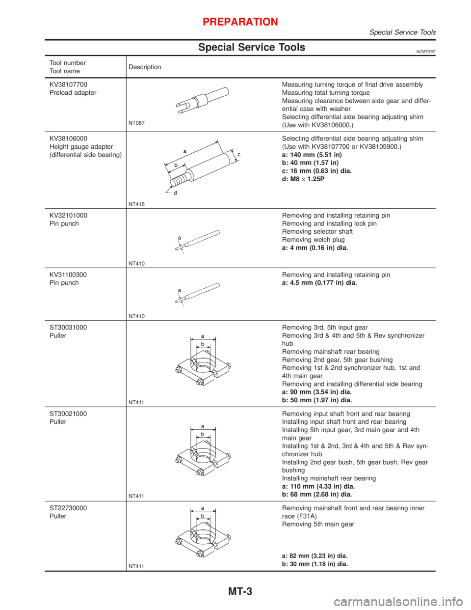
Special Service ToolsNCMT0001
Tool number
Tool nameDescription
KV38107700
Preload adapter
NT087
Measuring turning torque of final drive assembly
Measuring total turning torque
Measuring clearance between side gear and differ-
ential case with washer
Selecting differential side bearing adjusting shim
(Use with KV38106000.)
KV38106000
Height gauge adapter
(differential side bearing)
NT418
Selecting differential side bearing adjusting shim
(Use with KV38107700 or KV38105900.)
a: 140 mm (5.51 in)
b: 40 mm (1.57 in)
c: 16 mm (0.63 in) dia.
d: M8´1.25P
KV32101000
Pin punch
NT410
Removing and installing retaining pin
Removing and installing lock pin
Removing selector shaft
Removing welch plug
a: 4 mm (0.16 in) dia.
KV31100300
Pin punch
NT410
Removing and installing retaining pin
a: 4.5 mm (0.177 in) dia.
ST30031000
Puller
NT411
Removing 3rd, 5th input gear
Removing 3rd & 4th and 5th & Rev synchronizer
hub
Removing mainshaft rear bearing
Removing 2nd gear, 5th gear bushing
Removing 1st & 2nd synchronizer hub, 1st and
4th main gear
Removing and installing differential side bearing
a: 90 mm (3.54 in) dia.
b: 50 mm (1.97 in) dia.
ST30021000
Puller
NT411
Removing input shaft front and rear bearing
Installing input shaft front and rear bearing
Installing 5th input gear, 3rd main gear and 4th
main gear
Installing 1st & 2nd, 3rd & 4th and 5th & Rev syn-
chronizer hub
Installing 2nd gear bush, 5th gear bush, Rev gear
bushing
Installing mainshaft rear bearing
a: 110 mm (4.33 in) dia.
b: 68 mm (2.68 in) dia.
ST22730000
Puller
NT411
Removing mainshaft front and rear bearing inner
race (F31A)
Removing 5th main gear
a: 82 mm (3.23 in) dia.
b: 30 mm (1.18 in) dia.
PREPARATION
Special Service Tools
MT-3
Page 2113 of 2267
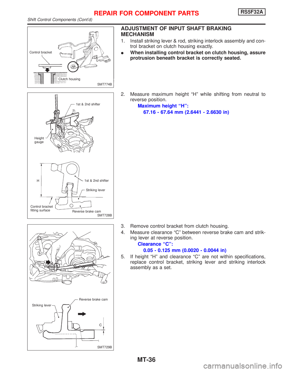
ADJUSTMENT OF INPUT SHAFT BRAKING
MECHANISM
1. Install striking lever & rod, striking interlock assembly and con-
trol bracket on clutch housing exactly.
IWhen installing control bracket on clutch housing, assure
protrusion beneath bracket is correctly seated.
2. Measure maximum height ªHº while shifting from neutral to
reverse position.
Maximum height ªHº:
67.16 - 67.64 mm (2.6441 - 2.6630 in)
3. Remove control bracket from clutch housing.
4. Measure clearance ªCº between reverse brake cam and strik-
ing lever at reverse position.
Clearance ªCº:
0.05 - 0.125 mm (0.0020 - 0.0044 in)
5. If height ªHº and clearance ªCº are not within specifications,
replace control bracket, striking lever and striking interlock
assembly as a set.
SMT774B Control bracket
Clutch housing
SMT728B 1st & 2nd shifter
Height
gauge
1st & 2nd shifter
Striking lever
Control bracket
fitting surface
.Reverse brake cam
SMT729B Reverse brake cam
Striking lever
REPAIR FOR COMPONENT PARTSRS5F32A
Shift Control Components (Cont'd)
MT-36