Page 1575 of 2267
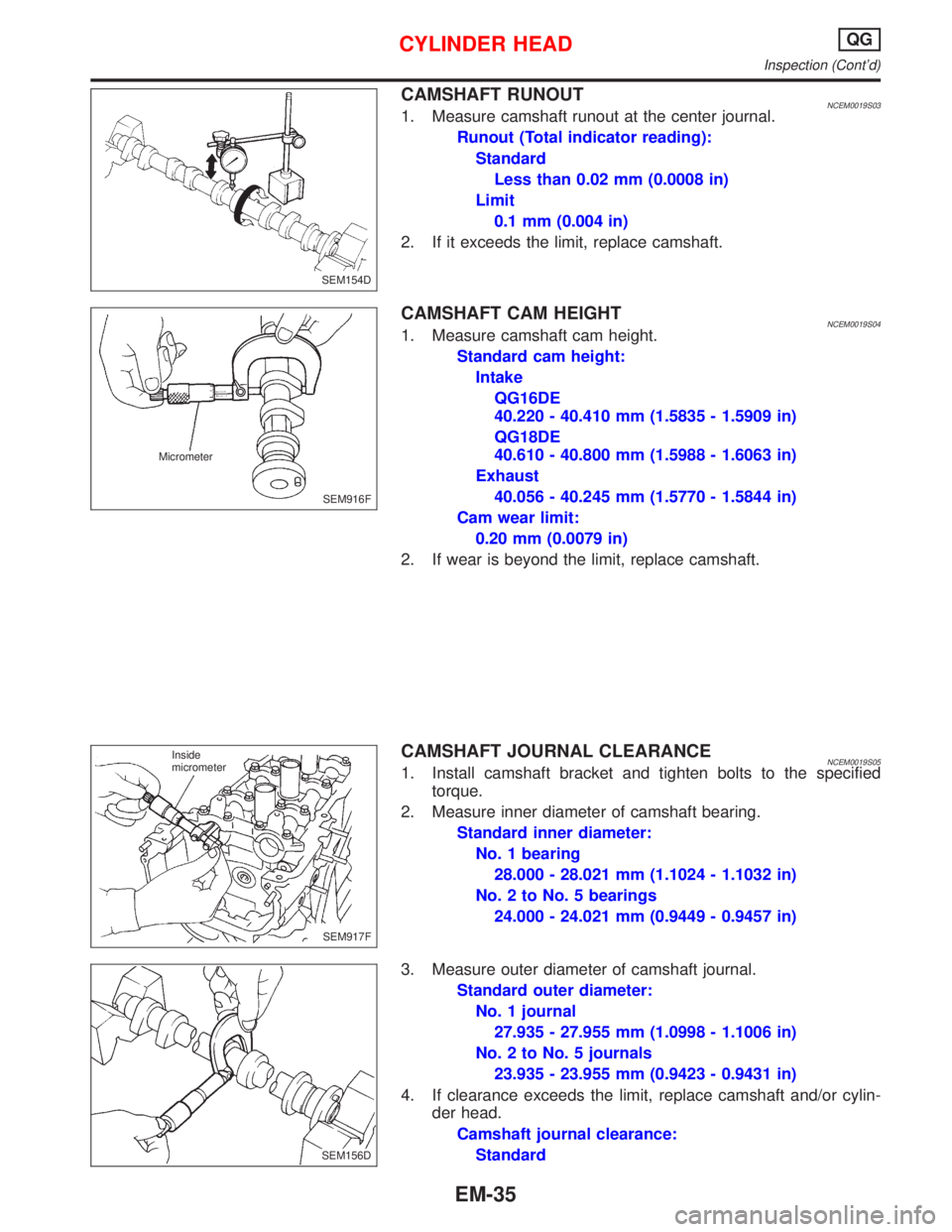
CAMSHAFT RUNOUTNCEM0019S031. Measure camshaft runout at the center journal.
Runout (Total indicator reading):
Standard
Less than 0.02 mm (0.0008 in)
Limit
0.1 mm (0.004 in)
2. If it exceeds the limit, replace camshaft.
CAMSHAFT CAM HEIGHTNCEM0019S041. Measure camshaft cam height.
Standard cam height:
Intake
QG16DE
40.220 - 40.410 mm (1.5835 - 1.5909 in)
QG18DE
40.610 - 40.800 mm (1.5988 - 1.6063 in)
Exhaust
40.056 - 40.245 mm (1.5770 - 1.5844 in)
Cam wear limit:
0.20 mm (0.0079 in)
2. If wear is beyond the limit, replace camshaft.
CAMSHAFT JOURNAL CLEARANCENCEM0019S051. Install camshaft bracket and tighten bolts to the specified
torque.
2. Measure inner diameter of camshaft bearing.
Standard inner diameter:
No. 1 bearing
28.000 - 28.021 mm (1.1024 - 1.1032 in)
No. 2 to No. 5 bearings
24.000 - 24.021 mm (0.9449 - 0.9457 in)
3. Measure outer diameter of camshaft journal.
Standard outer diameter:
No. 1 journal
27.935 - 27.955 mm (1.0998 - 1.1006 in)
No. 2 to No. 5 journals
23.935 - 23.955 mm (0.9423 - 0.9431 in)
4. If clearance exceeds the limit, replace camshaft and/or cylin-
der head.
Camshaft journal clearance:
Standard
SEM154D
SEM916F Micrometer
SEM917F Inside
micrometer
SEM156D
CYLINDER HEADQG
Inspection (Cont'd)
EM-35
Page 1580 of 2267
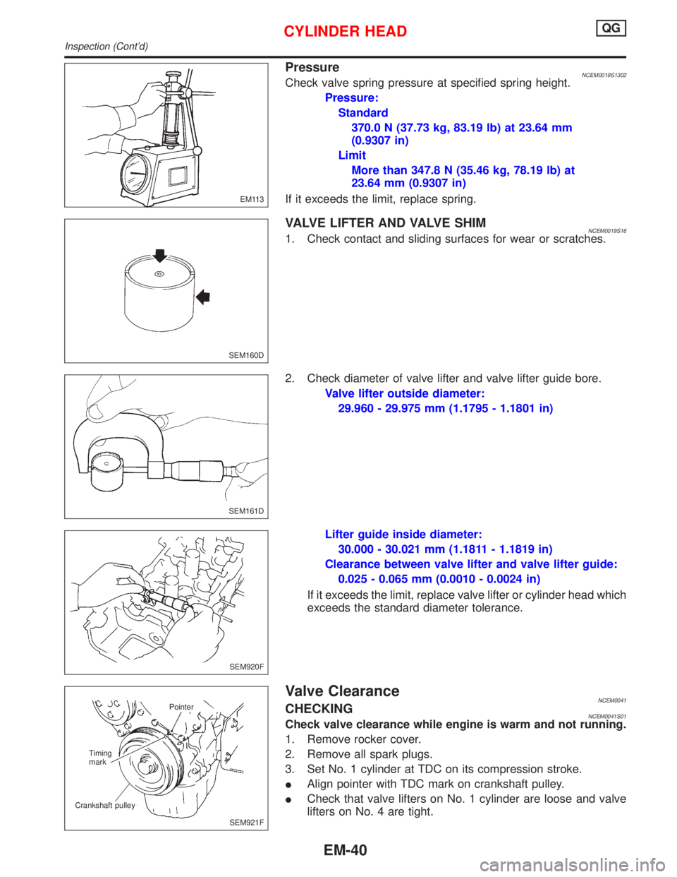
PressureNCEM0019S1302Check valve spring pressure at specified spring height.
Pressure:
Standard
370.0 N (37.73 kg, 83.19 lb) at 23.64 mm
(0.9307 in)
Limit
More than 347.8 N (35.46 kg, 78.19 lb) at
23.64 mm (0.9307 in)
If it exceeds the limit, replace spring.
VALVE LIFTER AND VALVE SHIMNCEM0019S161. Check contact and sliding surfaces for wear or scratches.
2. Check diameter of valve lifter and valve lifter guide bore.
Valve lifter outside diameter:
29.960 - 29.975 mm (1.1795 - 1.1801 in)
Lifter guide inside diameter:
30.000 - 30.021 mm (1.1811 - 1.1819 in)
Clearance between valve lifter and valve lifter guide:
0.025 - 0.065 mm (0.0010 - 0.0024 in)
If it exceeds the limit, replace valve lifter or cylinder head which
exceeds the standard diameter tolerance.
Valve ClearanceNCEM0041CHECKINGNCEM0041S01Check valve clearance while engine is warm and not running.
1. Remove rocker cover.
2. Remove all spark plugs.
3. Set No. 1 cylinder at TDC on its compression stroke.
IAlign pointer with TDC mark on crankshaft pulley.
ICheck that valve lifters on No. 1 cylinder are loose and valve
lifters on No. 4 are tight.
EM113
SEM160D
SEM161D
SEM920F
SEM921F Pointer
Timing
mark
Crankshaft pulley
CYLINDER HEADQG
Inspection (Cont'd)
EM-40
Page 1595 of 2267
If out of specification, replace piston ring. If gap exceeds maximum
limit with a new ring, rebore cylinder and use oversized piston and
piston rings.
Refer to SDS, EM-185.
IWhen replacing the piston, check the cylinder block surface for
scratches or seizure. If scratches or seizure is found, hone or
replace the cylinder block.
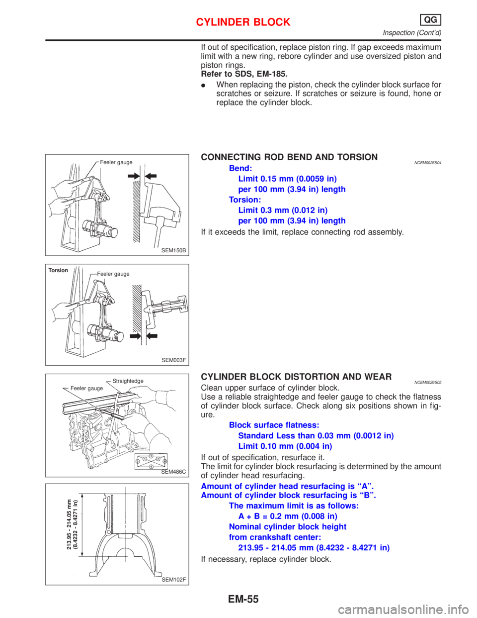
CONNECTING ROD BEND AND TORSIONNCEM0026S04Bend:
Limit 0.15 mm (0.0059 in)
per 100 mm (3.94 in) length
Torsion:
Limit 0.3 mm (0.012 in)
per 100 mm (3.94 in) length
If it exceeds the limit, replace connecting rod assembly.
CYLINDER BLOCK DISTORTION AND WEARNCEM0026S05Clean upper surface of cylinder block.
Use a reliable straightedge and feeler gauge to check the flatness
of cylinder block surface. Check along six positions shown in fig-
ure.
Block surface flatness:
Standard Less than 0.03 mm (0.0012 in)
Limit 0.10 mm (0.004 in)
If out of specification, resurface it.
The limit for cylinder block resurfacing is determined by the amount
of cylinder head resurfacing.
Amount of cylinder head resurfacing is ªAº.
Amount of cylinder block resurfacing is ªBº.
The maximum limit is as follows:
A + B = 0.2 mm (0.008 in)
Nominal cylinder block height
from crankshaft center:
213.95 - 214.05 mm (8.4232 - 8.4271 in)
If necessary, replace cylinder block.
SEM150B Feeler gauge
SEM003F Torsion
Feeler gauge
SEM486C Feeler gaugeStraightedge
SEM102F
213.95 - 214.05 mm
(8.4232 - 8.4271 in)
CYLINDER BLOCKQG
Inspection (Cont'd)
EM-55
Page 1631 of 2267
7. Remove valve components with Tool.
8. Remove valve oil seal with a suitable tool.
Inspection
CYLINDER HEAD DISTORTION
Head surface flatness:
Standard
Less than 0.03 mm (0.0012 in)
Limit
0.1 mm (0.004 in)
If beyond the specified limit, replace or resurface.
Resurfacing limit:
The limit of cylinder head is determined by the cylinder block
resurfacing in an engine.
Amount of cylinder head resurfacing is ªAº.
Amount of cylinder block resurfacing is ªBº.
The maximum limit is as follows:
A + B = 0.2 mm (0.008 in)
After resurfacing cylinder head, check that camshaft rotates freely
by hand. If resistance is felt, cylinder head must be replaced.
Nominal cylinder head height:
136.9 - 137.1 mm (5.390 - 5.398 in)
CAMSHAFT VISUAL CHECK
Check camshaft for scratches, seizure and wear.
SEM604E Compressor assemblyAttachment
SEM994C
SEM925C
CYLINDER HEADSR20DE
Inspection
EM-91
Page 1632 of 2267
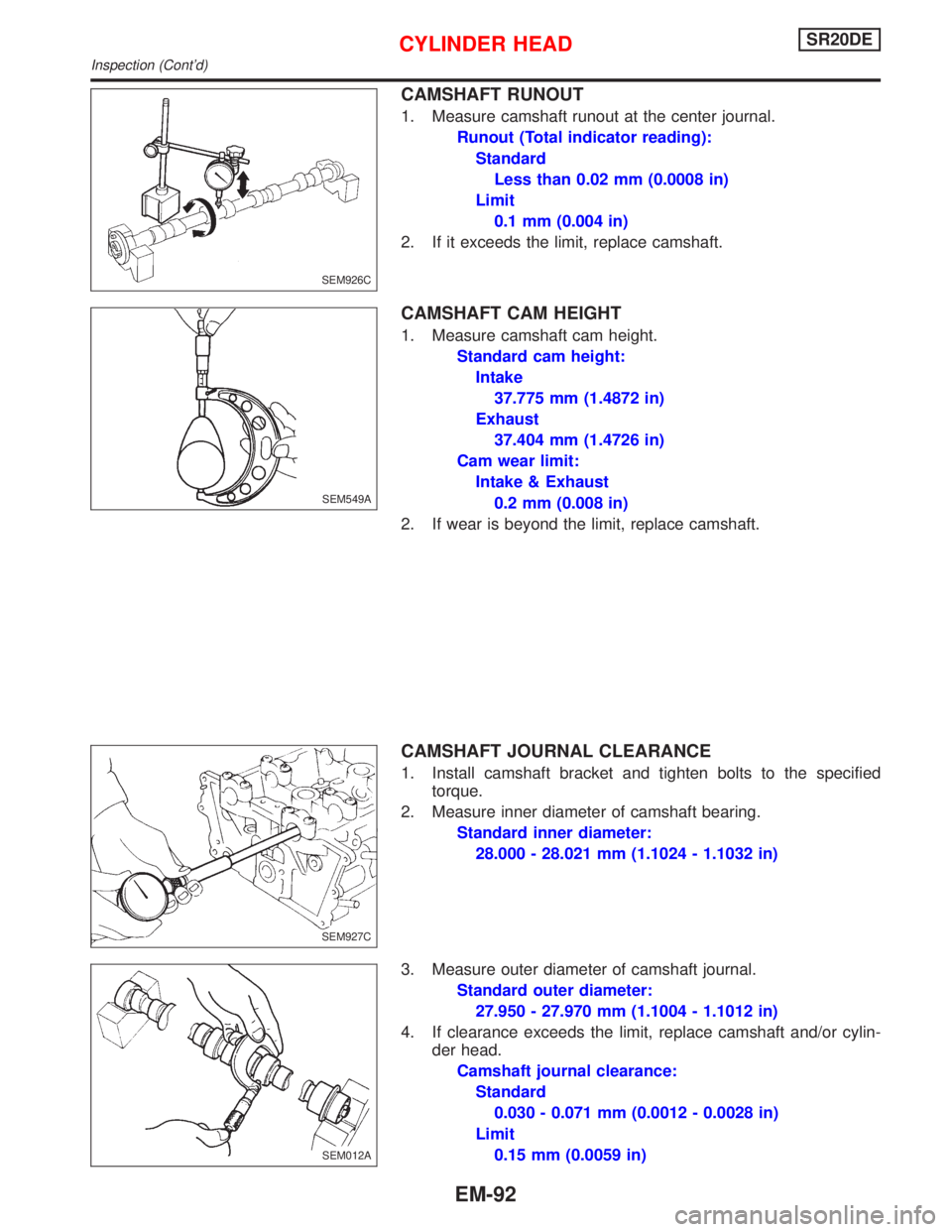
CAMSHAFT RUNOUT
1. Measure camshaft runout at the center journal.
Runout (Total indicator reading):
Standard
Less than 0.02 mm (0.0008 in)
Limit
0.1 mm (0.004 in)
2. If it exceeds the limit, replace camshaft.
CAMSHAFT CAM HEIGHT
1. Measure camshaft cam height.
Standard cam height:
Intake
37.775 mm (1.4872 in)
Exhaust
37.404 mm (1.4726 in)
Cam wear limit:
Intake & Exhaust
0.2 mm (0.008 in)
2. If wear is beyond the limit, replace camshaft.
CAMSHAFT JOURNAL CLEARANCE
1. Install camshaft bracket and tighten bolts to the specified
torque.
2. Measure inner diameter of camshaft bearing.
Standard inner diameter:
28.000 - 28.021 mm (1.1024 - 1.1032 in)
3. Measure outer diameter of camshaft journal.
Standard outer diameter:
27.950 - 27.970 mm (1.1004 - 1.1012 in)
4. If clearance exceeds the limit, replace camshaft and/or cylin-
der head.
Camshaft journal clearance:
Standard
0.030 - 0.071 mm (0.0012 - 0.0028 in)
Limit
0.15 mm (0.0059 in)
SEM926C
SEM549A
SEM927C
.SEM012A
CYLINDER HEADSR20DE
Inspection (Cont'd)
EM-92
Page 1636 of 2267
VALVE SPRING
Squareness
1. Measure ªSº dimension.
Out-of-square:
Less than 2.2 mm (0.087 in)
2. If it exceeds the limit, replace spring.
Free height
Check free height: 49.36 mm (1.9433 in)
Pressure
Check valve spring pressure.
Pressure: N (kg, lb) at height mm (in)
Standard
519 - 571 (52.9 - 58.2, 116.6 - 128.3) at 27 (1.063)
Limit
Replace if load is less than 501 (51.1 - 112.7) at
27 (1.063)
HYDRAULIC LASH ADJUSTER
1. Check contact and sliding surfaces for wear or scratches.
2. Check diameter of lash adjuster.
Outer diameter:
16.980 - 16.993 mm (0.6685 - 0.6690 in)
3. Check lash adjuster guide inner diameter.
Inner diameter:
17.000 - 17.020 mm (0.6693 - 0.6701 in)
Standard clearance between lash adjuster and
adjuster guide:
0.007 - 0.040 mm (0.0003 - 0.0016 in)
SEM288A S (Out-of-square)
EM113
SEM935C
SEM936C
.SEM084D
CYLINDER HEADSR20DE
Inspection (Cont'd)
EM-96
Page 1652 of 2267
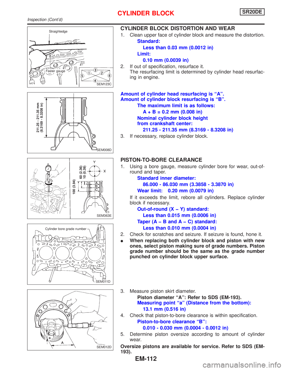
CYLINDER BLOCK DISTORTION AND WEAR
1. Clean upper face of cylinder block and measure the distortion.
Standard:
Less than 0.03 mm (0.0012 in)
Limit:
0.10 mm (0.0039 in)
2. If out of specification, resurface it.
The resurfacing limit is determined by cylinder head resurfac-
ing in engine.
Amount of cylinder head resurfacing is ªAº.
Amount of cylinder block resurfacing is ªBº.
The maximum limit is as follows:
A + B = 0.2 mm (0.008 in)
Nominal cylinder block height
from crankshaft center:
211.25 - 211.35 mm (8.3169 - 8.3208 in)
3. If necessary, replace cylinder block.
PISTON-TO-BORE CLEARANCE
1. Using a bore gauge, measure cylinder bore for wear, out-of-
round and taper.
Standard inner diameter:
86.000 - 86.030 mm (3.3858 - 3.3870 in)
Wear limit: 0.20 mm (0.0079 in)
If it exceeds the limit, rebore all cylinders. Replace cylinder
block if necessary.
Out-of-round (X þ Y) standard:
Less than 0.015 mm (0.0006 in)
Taper (A þ B and A þ C) standard:
Less than 0.010 mm (0.0004 in)
2. Check for scratches and seizure. If seizure is found, hone it.
IWhen replacing both cylinder block and piston with new
ones, select piston making sure of grade numbers. Piston
grade number should be the same as the grade number
punched on cylinder block upper surface.
3. Measure piston skirt diameter.
Piston diameter ªAº: Refer to SDS (EM-193).
Measuring point ªaº (Distance from the bottom):
13.1 mm (0.516 in)
4. Check that piston-to-bore clearance is within specification.
Piston-to-bore clearance ªBº:
0.010 - 0.030 mm (0.0004 - 0.0012 in)
5. Determine piston oversize according to amount of cylinder
wear.
Oversize pistons are available for service. Refer to SDS (EM-
193).
SEM123C Straightedge
Feeler gauge
SEM008D
211.25 - 211.35 mm
(8.3169 - 8.3208 in)
SEM363E
100 (3.94)
60 (2.36)
10 (0.39)
.SEM011D
Cylinder bore grade number
SEM012D
CYLINDER BLOCKSR20DE
Inspection (Cont'd)
EM-112
Page 1682 of 2267
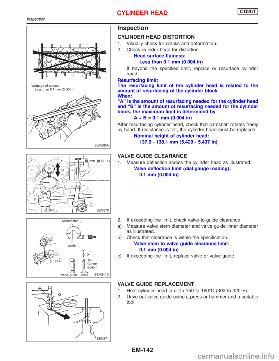
Inspection
CYLINDER HEAD DISTORTION
1. Visually check for cracks and deformation.
2. Check cylinder head for distortion.
Head surface flatness:
Less than 0.1 mm (0.004 in)
If beyond the specified limit, replace or resurface cylinder
head.
Resurfacing limit:
The resurfacing limit of the cylinder head is related to the
amount of resurfacing of the cylinder block.
When:
ªAº is the amount of resurfacing needed for the cylinder head
and ªBº is the amount of resurfacing needed for the cylinder
block, the maximum limit is determined by
A + B = 0.1 mm (0.004 in)
After resurfacing cylinder head, check that camshaft rotates freely
by hand. If resistance is felt, the cylinder head must be replaced.
Nominal height of cylinder head:
137.9 - 138.1 mm (5.429 - 5.437 in)
VALVE GUIDE CLEARANCE
1. Measure deflection across the cylinder head as illustrated.
Valve deflection limit (dial gauge reading):
0.1 mm (0.004 in)
2. If exceeding the limit, check valve-to-guide clearance.
a) Measure valve stem diameter and valve guide inner diameter
as illustrated.
b) Check that clearance is within the specification.
Valve stem to valve guide clearance limit:
0.1 mm (0.004 in)
c) If exceeding the limit, replace valve or valve guide.
VALVE GUIDE REPLACEMENT
1. Heat cylinder head in oil to 150 to 160ÉC (302 to 320ÉF).
2. Drive out valve guide using a press or hammer and a suitable
tool.
SEM595A Warpage of surface:
Less than 0.1 mm (0.004 in)
SEM870
SEM244D Micrometer
To p
Center
Bottom
Valve guide Valve
SEM871
CYLINDER HEADCD20T
Inspection
EM-142