1999 NISSAN PRIMERA battery
[x] Cancel search: batteryPage 1828 of 2267
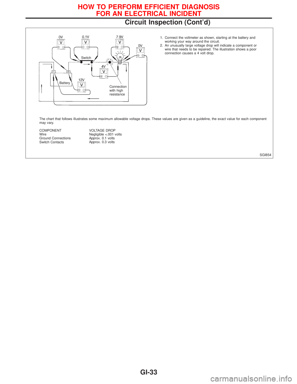
SGI854 1. Connect the voltmeter as shown, starting at the battery and
working your way around the circuit.
2. An unusually large voltage drop will indicate a component or
wire that needs to be repaired. The illustration shows a poor
connection causes a 4 volt drop.
The chart that follows illustrates some maximum allowable voltage drops. These values are given as a guideline, the exact value for each component
may vary.
COMPONENT
Wire
Ground Connections
Switch ContactsVOLTAGE DROP
Negligible <.001 volts
Approx. 0.1 volts
Approx. 0.3 volts BatterySwitch
Connection
with high
resistance
HOW TO PERFORM EFFICIENT DIAGNOSIS
FOR AN ELECTRICAL INCIDENT
Circuit Inspection (Cont'd)
GI-33
Page 1829 of 2267
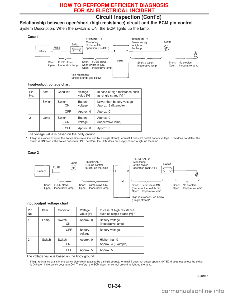
Relationship between open/short (high resistance) circuit and the ECM pin control
System Description: When the switch is ON, the ECM lights up the lamp.
SGI849-A
Case 1
BatteryFUSESwitchTERMINAL: 1
Monitoring
of the switch
operation (ON/OFF)TERMINAL: 2
Power supply
to light up
the lampLamp
Short: FUSE blows.
Open: Inoperative lampShort: FUSE blows
when switch is ON.
Open: Inoperative lamp
High resistance:
(Single strand) See below.*ECM
Short & Open:
Inoperative lampShort: No problem
Open: Inoperative lamp
Case 2
BatteryFUSELampTERMINAL: 1
Ground control
to light up the lampTERMINAL: 2
Monitoring
of the switch
operation (ON/OFF)Switch
Short: FUSE blows.
Open: Inoperative lampShort: Lamp stays ON.
Open: Inoperative lampShort: Lamp stays ON.
(Same as the switch ON)
Open: Inoperative lamp
High resistance: See below.
(Single strand)*Short: No problem
Open: Inoperative lamp ECM
Pin
No.Item Condition Voltage
value [V]In case of high resistance such
as single strand [V] *
1 Switch Switch Battery Lower than battery voltage
ON voltage Approx. 8 (Example)
OFF Approx. 0 Approx. 0
2 Lamp Switch Battery Approx. 0
ON voltage (Inoperative lamp)
OFF Approx. 0 Approx. 0
The voltage value is based on the body ground.
Input-output voltage chart
Pin
No.Item Condition Voltage
value [V]In case of high resistance
such as single strand [V] *
1 Lamp Switch Approx. 0 Battery voltage
ON (Inoperative lamp)
OFF Battery
voltageBattery voltage
2 Switch Switch Approx. 0 Higher than 0
ON Approx. 4 (Example)
OFF Approx. 5 Approx. 5
The voltage value is based on the body ground.
Input-output voltage chart
* : If high resistance exists in the switch side circuit (caused by a single strand), terminal 1 does not detect battery voltage. ECM does not detect the
switch is ON even if the switch does turn ON. Therefore, the ECM does not supply power to light up the lamp.
* : If high resistance exists in the switch side circuit (caused by a single strand), terminal 2 does not detect approx. 0V. ECM does not detect the switch
is ON even if the switch does turn ON. Therefore, the ECM does not control ground to light up the lamp.
HOW TO PERFORM EFFICIENT DIAGNOSIS
FOR AN ELECTRICAL INCIDENT
Circuit Inspection (Cont'd)
GI-34
Page 1830 of 2267
NOTICE
Trouble diagnoses indicates work procedures required to diag-
nose problems effectively. Observe the following instructions
before diagnosing.
1) Before performing trouble diagnoses, read the ªPrelimi-
nary Checkº, the ªSymptom Chartº or the ªWork Flowº.
2) After repairs, re-check that the problem has been com-
pletely eliminated.
3) Refer to Component Parts and Harness Connector Loca-
tion for the Systems described in each section for
identification/location of components and harness con-
nectors.
4) Refer to the Circuit Diagram for Quick Pinpoint Check.
If you need to check circuit continuity between harness
connectors in more detail, such as when a sub-harness
is used, refer to Wiring Diagram in each individual sec-
tion and Harness Layout in EL section for identification
of harness connectors.
5) When checking circuit continuity, ignition switch should
be in the ªLOCKº position.
6) Before checking voltage at connectors, check battery
voltage.
7) After accomplishing the Diagnostic Procedures and
Electrical Components Inspection, make sure that all
harness connectors are reconnected as they were.
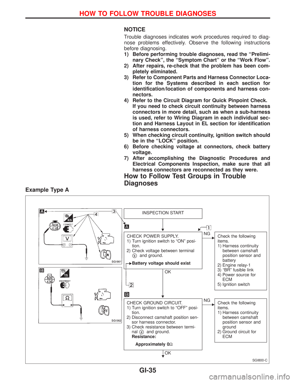
How to Follow Test Groups in Trouble
Diagnoses
Example Type A
SGI800-C
INSPECTION START
CHECK POWER SUPPLY.
1) Turn ignition switch to ªONº posi-
tion.
2) Check voltage between terminal
pband ground.
Battery voltage should exist
OK
ENG
Check the following
items.
1) Harness continuity
between camshaft
position sensor and
battery
2) Engine relay-1
3) ªBRº fusible link
4) Power source for
ECM
5) Ignition switch
CHECK GROUND CIRCUIT.
1) Turn ignition switch to ªOFFº posi-
tion.
2) Disconnect camshaft position sen-
sor harness connector.
3) Check resistance between termi-
nal
pdand ground.
Resistance:
Approximately 0W
OK
ENG
Check the following
items.
1) Harness continuity
between camshaft
position sensor and
ground
2) Ground circuit for
ECM
H
H
H
HOW TO FOLLOW TROUBLE DIAGNOSES
GI-35
Page 1831 of 2267
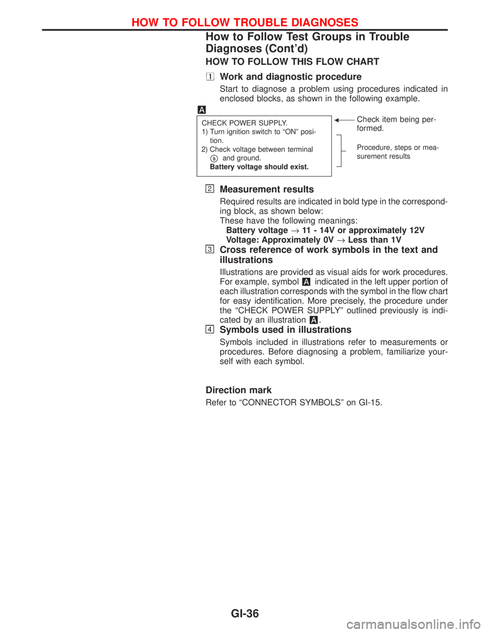
HOW TO FOLLOW THIS FLOW CHART
Work and diagnostic procedure
Start to diagnose a problem using procedures indicated in
enclosed blocks, as shown in the following example.
CHECK POWER SUPPLY.
1) Turn ignition switch to ªONº posi-
tion.
2) Check voltage between terminal
pband ground.
Battery voltage should exist.
FCheck item being per-
formed.
Procedure, steps or mea-
surement results
Measurement results
Required results are indicated in bold type in the correspond-
ing block, as shown below:
These have the following meanings:
Battery voltage®11 - 14V or approximately 12V
Voltage: Approximately 0V®Less than 1V
Cross reference of work symbols in the text and
illustrations
Illustrations are provided as visual aids for work procedures.
For example, symbol
indicated in the left upper portion of
each illustration corresponds with the symbol in the flow chart
for easy identification. More precisely, the procedure under
the ªCHECK POWER SUPPLYº outlined previously is indi-
cated by an illustration
.
Symbols used in illustrations
Symbols included in illustrations refer to measurements or
procedures. Before diagnosing a problem, familiarize your-
self with each symbol.
Direction mark
Refer to ªCONNECTOR SYMBOLSº on GI-15.
HOW TO FOLLOW TROUBLE DIAGNOSES
How to Follow Test Groups in Trouble
Diagnoses (Cont'd)
GI-36
Page 1832 of 2267
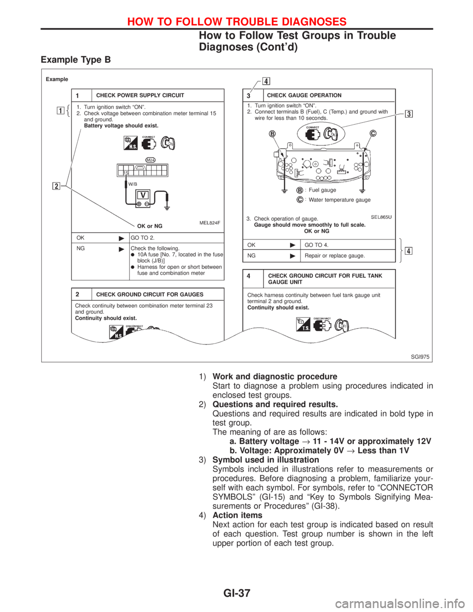
Example Type B
1)Work and diagnostic procedure
Start to diagnose a problem using procedures indicated in
enclosed test groups.
2)Questions and required results.
Questions and required results are indicated in bold type in
test group.
The meaning of are as follows:
a. Battery voltage®11 - 14V or approximately 12V
b. Voltage: Approximately 0V®Less than 1V
3)Symbol used in illustration
Symbols included in illustrations refer to measurements or
procedures. Before diagnosing a problem, familiarize your-
self with each symbol. For symbols, refer to ªCONNECTOR
SYMBOLSº (GI-15) and ªKey to Symbols Signifying Mea-
surements or Proceduresº (GI-38).
4)Action items
Next action for each test group is indicated based on result
of each question. Test group number is shown in the left
upper portion of each test group.
SGI975
Example
CHECK POWER SUPPLY CIRCUIT
1. Turn ignition switch ªONº.
2. Check voltage between combination meter terminal 15
and ground.
Battery voltage should exist.
OK or NG
OK
NGGO TO 2.
Check the following.
l10A fuse [No. 7, located in the fuse
block (J/B)]
lHarness for open or short between
fuse and combination meter
CHECK GROUND CIRCUIT FOR GAUGES
Check continuity between combination meter terminal 23
and ground.
Continuity should exist.CHECK GAUGE OPERATION
1. Turn ignition switch ªONº.
2. Connect terminals B (Fuel), C (Temp.) and ground with
wire for less than 10 seconds.
Fuel gauge
Water temperature gauge
3. Check operation of gauge.
Gauge should move smoothly to full scale.
OK or NG
OK
NGGO TO 4.
Repair or replace gauge.
CHECK GROUND CIRCUIT FOR FUEL TANK
GAUGE UNIT
Check harness continuity between fuel tank gauge unit
terminal 2 and ground.
Continuity should exist.
HOW TO FOLLOW TROUBLE DIAGNOSES
How to Follow Test Groups in Trouble
Diagnoses (Cont'd)
GI-37
Page 1833 of 2267
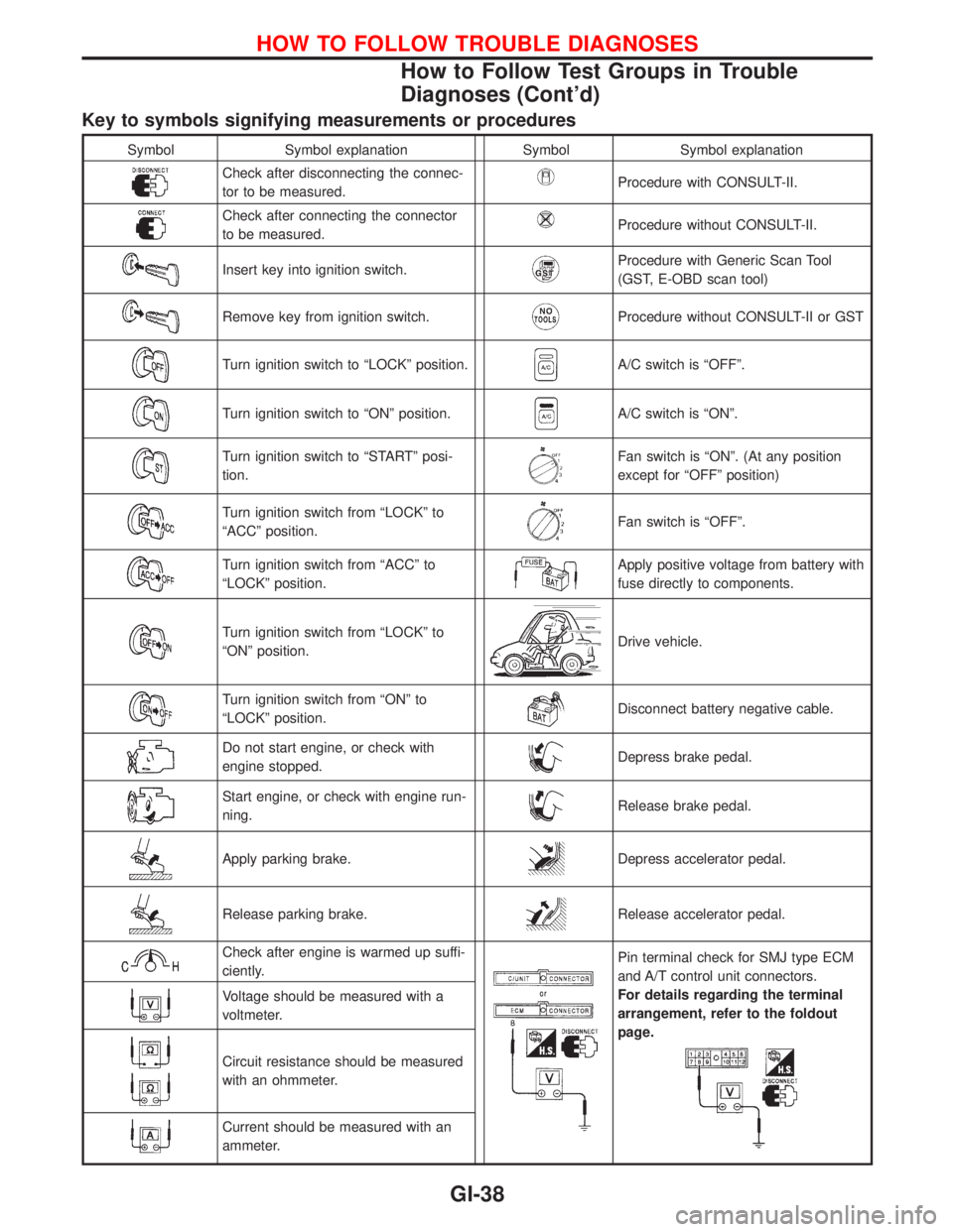
Key to symbols signifying measurements or procedures
Symbol Symbol explanation Symbol Symbol explanation
Check after disconnecting the connec-
tor to be measured.Procedure with CONSULT-II.
Check after connecting the connector
to be measured.Procedure without CONSULT-II.
Insert key into ignition switch.Procedure with Generic Scan Tool
(GST, E-OBD scan tool)
Remove key from ignition switch.Procedure without CONSULT-II or GST
Turn ignition switch to ªLOCKº position.A/C switch is ªOFFº.
Turn ignition switch to ªONº position.A/C switch is ªONº.
Turn ignition switch to ªSTARTº posi-
tion.Fan switch is ªONº. (At any position
except for ªOFFº position)
Turn ignition switch from ªLOCKº to
ªACCº position.Fan switch is ªOFFº.
Turn ignition switch from ªACCº to
ªLOCKº position.Apply positive voltage from battery with
fuse directly to components.
Turn ignition switch from ªLOCKº to
ªONº position.Drive vehicle.
Turn ignition switch from ªONº to
ªLOCKº position.Disconnect battery negative cable.
Do not start engine, or check with
engine stopped.Depress brake pedal.
Start engine, or check with engine run-
ning.Release brake pedal.
Apply parking brake.Depress accelerator pedal.
Release parking brake.Release accelerator pedal.
Check after engine is warmed up suffi-
ciently.Pin terminal check for SMJ type ECM
and A/T control unit connectors.
For details regarding the terminal
arrangement, refer to the foldout
page.
Voltage should be measured with a
voltmeter.
Circuit resistance should be measured
with an ohmmeter.
Current should be measured with an
ammeter.
HOW TO FOLLOW TROUBLE DIAGNOSES
How to Follow Test Groups in Trouble
Diagnoses (Cont'd)
GI-38
Page 1834 of 2267
Function and System Application
Diagnostic
test modeFunction ENGINE H×CVT ABSAIR
BAGNATS
Work supportThis mode enables a technician to adjust some devices faster
and more accurate by following the indications on CONSULT-II.´ÐÐÐÐ
Self-diagnostic
resultsSelf-diagnostic results can be read and erased quickly.´xx´´
Trouble diagnostic
recordCurrent self-diagnostic results and all trouble diagnostic records
previously stored can be read.ÐÐÐxÐ
ECU discriminated
No.Classification number of a replacement ECU can be read to pre-
vent an incorrect ECU from being installed.ÐÐдÐ
Data monitor Input/Output data in the ECM can be read.´xxÐÐ
DTC work supportThis mode enables a technician to set operating conditions to
confirm self-diagnosis status/results.x x ÐÐÐ
Active testDiagnostic Test Mode in which CONSULT-II drives some actua-
tors apart from the ECMs and also shifts some parameters in a
specified range.´ÐxÐÐ
ECM part number ECM part number can be read.´xxÐÐ
Control unit initialisa-
tionAll registered ignition key IDs in NATS components can be initia-
lised and new IDs can be registered.ÐÐÐÐ x
DTC & SRT confirma-
tionThe results of SRT (System Readiness Test) and the self-diag-
nosis status/results can be confirmed.x ÐÐÐÐ
´: Applicable
*1: NATS: Nissan Anti-Theft System
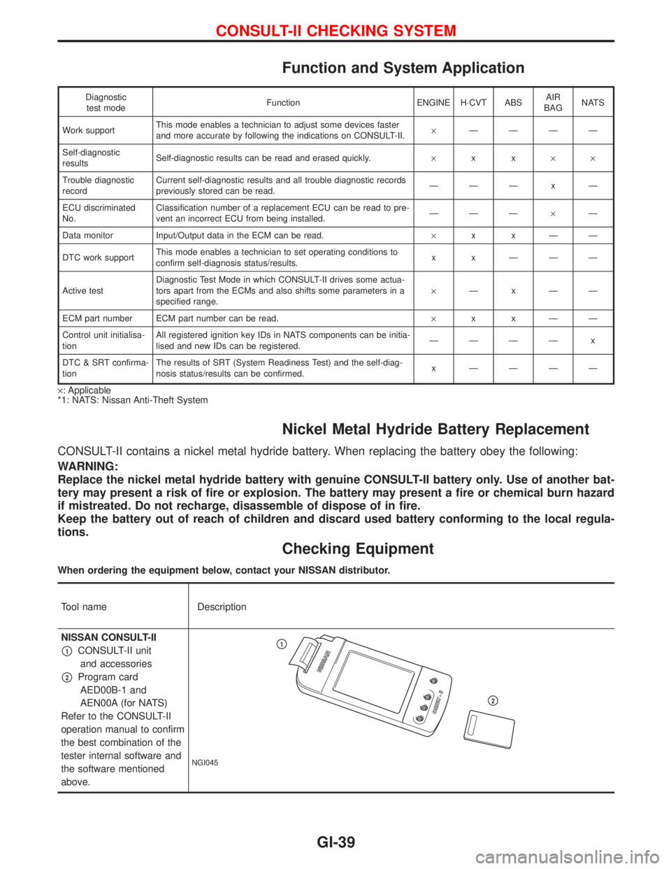
Nickel Metal Hydride Battery Replacement
CONSULT-II contains a nickel metal hydride battery. When replacing the battery obey the following:
WARNING:
Replace the nickel metal hydride battery with genuine CONSULT-II battery only. Use of another bat-
tery may present a risk of fire or explosion. The battery may present a fire or chemical burn hazard
if mistreated. Do not recharge, disassemble of dispose of in fire.
Keep the battery out of reach of children and discard used battery conforming to the local regula-
tions.
Checking Equipment
When ordering the equipment below, contact your NISSAN distributor.
Tool name Description
NISSAN CONSULT-II
p1CONSULT-II unit
and accessories
p2Program card
AED00B-1 and
AEN00A (for NATS)
Refer to the CONSULT-II
operation manual to confirm
the best combination of the
tester internal software and
the software mentioned
above.
NGI045
p1
p2
CONSULT-II CHECKING SYSTEM
GI-39
Page 1883 of 2267
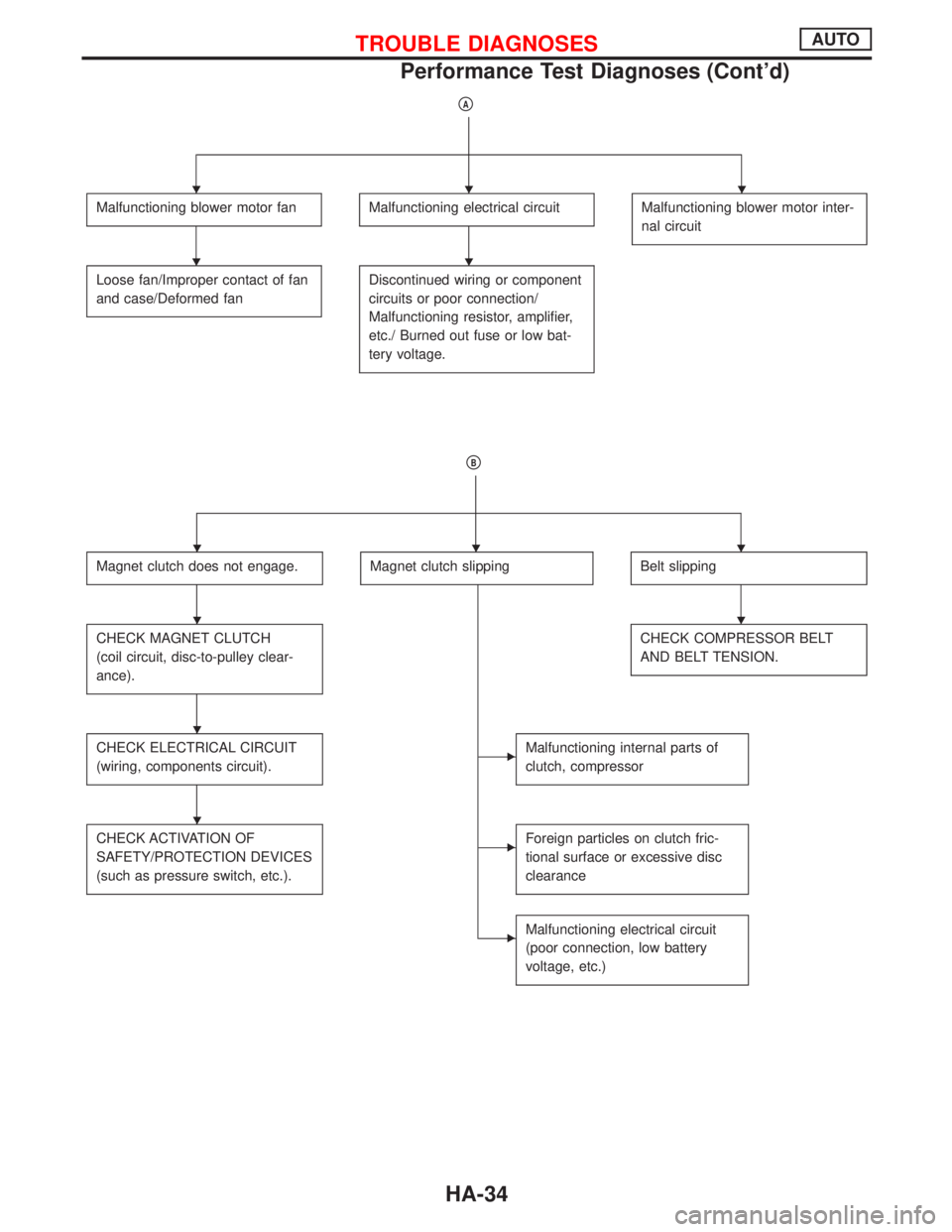
pA
Malfunctioning blower motor fanMalfunctioning electrical circuitMalfunctioning blower motor inter-
nal circuit
Loose fan/Improper contact of fan
and case/Deformed fanDiscontinued wiring or component
circuits or poor connection/
Malfunctioning resistor, amplifier,
etc./ Burned out fuse or low bat-
tery voltage.
pB
Magnet clutch does not engage.Magnet clutch slippingBelt slipping
CHECK MAGNET CLUTCH
(coil circuit, disc-to-pulley clear-
ance).CHECK COMPRESSOR BELT
AND BELT TENSION.
CHECK ELECTRICAL CIRCUIT
(wiring, components circuit).EMalfunctioning internal parts of
clutch, compressor
CHECK ACTIVATION OF
SAFETY/PROTECTION DEVICES
(such as pressure switch, etc.).EForeign particles on clutch fric-
tional surface or excessive disc
clearance
EMalfunctioning electrical circuit
(poor connection, low battery
voltage, etc.)
HHH
HH
HHH
HH
H
H
TROUBLE DIAGNOSESAUTO
Performance Test Diagnoses (Cont'd)
HA-34