1999 NISSAN PRIMERA battery
[x] Cancel search: batteryPage 1801 of 2267
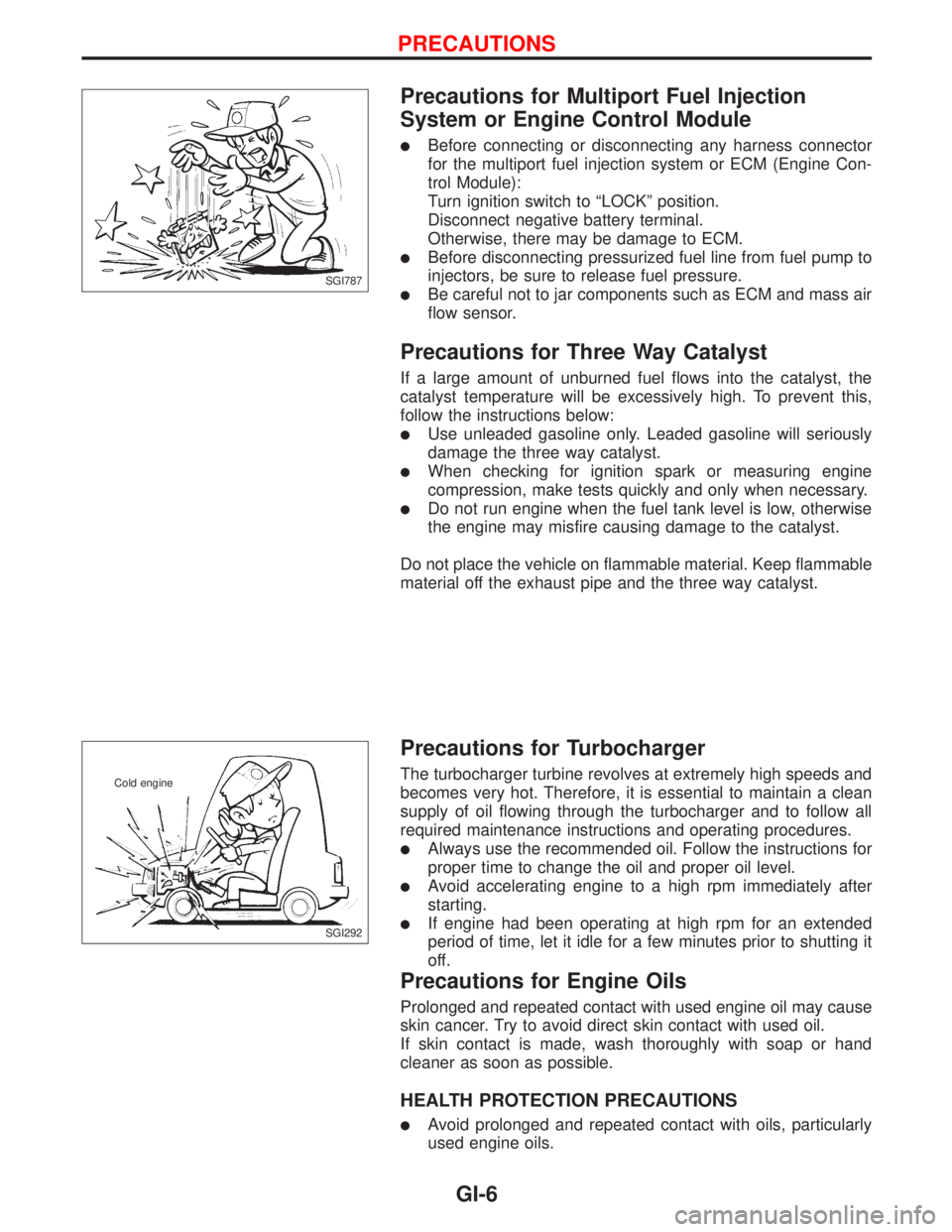
Precautions for Multiport Fuel Injection
System or Engine Control Module
lBefore connecting or disconnecting any harness connector
for the multiport fuel injection system or ECM (Engine Con-
trol Module):
Turn ignition switch to ªLOCKº position.
Disconnect negative battery terminal.
Otherwise, there may be damage to ECM.
lBefore disconnecting pressurized fuel line from fuel pump to
injectors, be sure to release fuel pressure.
lBe careful not to jar components such as ECM and mass air
flow sensor.
Precautions for Three Way Catalyst
If a large amount of unburned fuel flows into the catalyst, the
catalyst temperature will be excessively high. To prevent this,
follow the instructions below:
lUse unleaded gasoline only. Leaded gasoline will seriously
damage the three way catalyst.
lWhen checking for ignition spark or measuring engine
compression, make tests quickly and only when necessary.
lDo not run engine when the fuel tank level is low, otherwise
the engine may misfire causing damage to the catalyst.
Do not place the vehicle on flammable material. Keep flammable
material off the exhaust pipe and the three way catalyst.
Precautions for Turbocharger
The turbocharger turbine revolves at extremely high speeds and
becomes very hot. Therefore, it is essential to maintain a clean
supply of oil flowing through the turbocharger and to follow all
required maintenance instructions and operating procedures.
lAlways use the recommended oil. Follow the instructions for
proper time to change the oil and proper oil level.
lAvoid accelerating engine to a high rpm immediately after
starting.
lIf engine had been operating at high rpm for an extended
period of time, let it idle for a few minutes prior to shutting it
off.
Precautions for Engine Oils
Prolonged and repeated contact with used engine oil may cause
skin cancer. Try to avoid direct skin contact with used oil.
If skin contact is made, wash thoroughly with soap or hand
cleaner as soon as possible.
HEALTH PROTECTION PRECAUTIONS
lAvoid prolonged and repeated contact with oils, particularly
used engine oils.
SGI787
SGI292 Cold engine
PRECAUTIONS
GI-6
Page 1806 of 2267
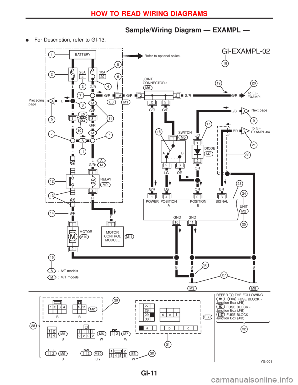
Sample/Wiring Diagram Ð EXAMPL Ð
lFor Description, refer to GI-13.
YGI001
Refer to optional splice. BATTERY
Preceding
page
RELAY
MOTOR
MOTOR
CONTROL
MODULE
A/T models
M/T models
.REFER TO THE FOLLOWINGM1,E103FUSE BLOCK -
Junction Box (J/B)
M2FUSE BLOCK -
Junction Box (J/B)
E127FUSE BLOCK -
Junction Box (J/B) POWER JOINT
CONNECTOR-1
SWITCHTo EL-
EXAMPL
Next page
To GI-
EXAMPL-04
DIODE
POSITION
APOSITION
BSIGNAL
GND GNDUNIT
HOW TO READ WIRING DIAGRAMS
GI-11
Page 1807 of 2267
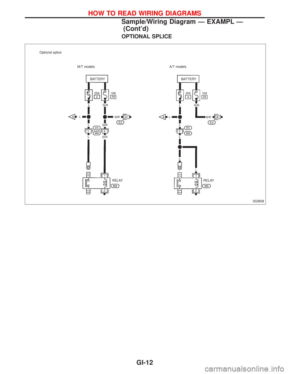
OPTIONAL SPLICE
SGI858 BATTERY BATTERY Optional splice
M/T models A/T models
RELAY RELAY
HOW TO READ WIRING DIAGRAMS
Sample/Wiring Diagram Ð EXAMPL Ð
(Cont'd)
GI-12
Page 1808 of 2267
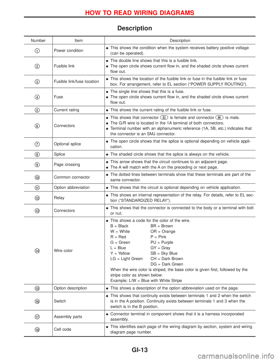
Description
Number Item Description
p1Power conditionlThis shows the condition when the system receives battery positive voltage
(can be operated).
p2Fusible link
lThe double line shows that this is a fusible link.
lThe open circle shows current flow in, and the shaded circle shows current
flow out.
p3Fusible link/fuse locationlThis shows the location of the fusible link or fuse in the fusible link or fuse
box. For arrangement, refer to EL section (ªPOWER SUPPLY ROUTINGº).
p4Fuse
lThe single line shows that this is a fuse.
lThe open circle shows current flow in, and the shaded circle shows current
flow out.
p5Current ratinglThis shows the current rating of the fusible link or fuse.
p6Connectors
lThis shows that connectorE3is female and connectorM1is male.
lThe G/R wire is located in the 1A terminal of both connectors.
lTerminal number with an alphanumeric reference (1A, 5B, etc.) indicates that
the connector is an SMJ connector.
p7Optional splicelThe open circle shows that the splice is optional depending on vehicle appli-
cation.
p8SplicelThe shaded circle shows that the splice is always on the vehicle.
p9Page crossinglThis arrow shows that the circuit continues to an adjacent page.
lThe A will match with the A on the preceding or next page.
p10Common connectorlThe dotted lines between terminals show that these terminals are part of the
same connector.
p11Option abbreviationlThis shows that the circuit is optional depending on vehicle application.
p12RelaylThis shows an internal representation of the relay. For details, refer to EL sec-
tion (ªSTANDARDIZED RELAYº).
p13ConnectorslThis shows that the connector is connected to the body or a terminal with bolt
or nut.
p14Wire color
lThis shows a code for the color of the wire.
B = Black BR = Brown
W = White OR = Orange
R = Red P = Pink
G = Green PU = Purple
L = Blue GY = Gray
Y = Yellow SB = Sky Blue
LG = Light Green CH = Dark Brown
DG = Dark Green
When the wire color is striped, the base color is given first, followed by the
stripe color as shown below:
Example: L/W = Blue with White Stripe
p15Option descriptionlThis shows a description of the option abbreviation used on the page.
p16Switch
lThis shows that continuity exists between terminals 1 and 2 when the switch
is in the A position. Continuity exists between terminals 1 and 3 when the
switch is in the B position.
p17Assembly partslConnector terminal in component shows that it is a harness incorporated
assembly.
p18Cell codelThis identifies each page of the wiring diagram by section, system and wiring
diagram page number.
HOW TO READ WIRING DIAGRAMS
GI-13
Page 1824 of 2267
Circuit Inspection
INTRODUCTION
In general, testing electrical circuits is an easy task if it is approached in a logical and organized method.
Before beginning it is important to have all available information on the system to be tested. Also, get a
thorough understanding of system operation. Then you will be able to use the appropriate equipment and
follow the correct test procedure.
You may have to simulate vehicle vibrations while testing electrical components.Gently shakethe wiring
harness or electrical component to do this.
OPEN A circuit is open when there is no continuity through a section of the circuit.
SHORT There are two types of shorts.
lSHORT CIRCUITWhen a circuit contacts another circuit and causes the
normal resistance to change.
lSHORT TO GROUNDWhen a circuit contacts a ground source and grounds the
circuit.
TESTING FOR ªOPENSº IN THE CIRCUIT
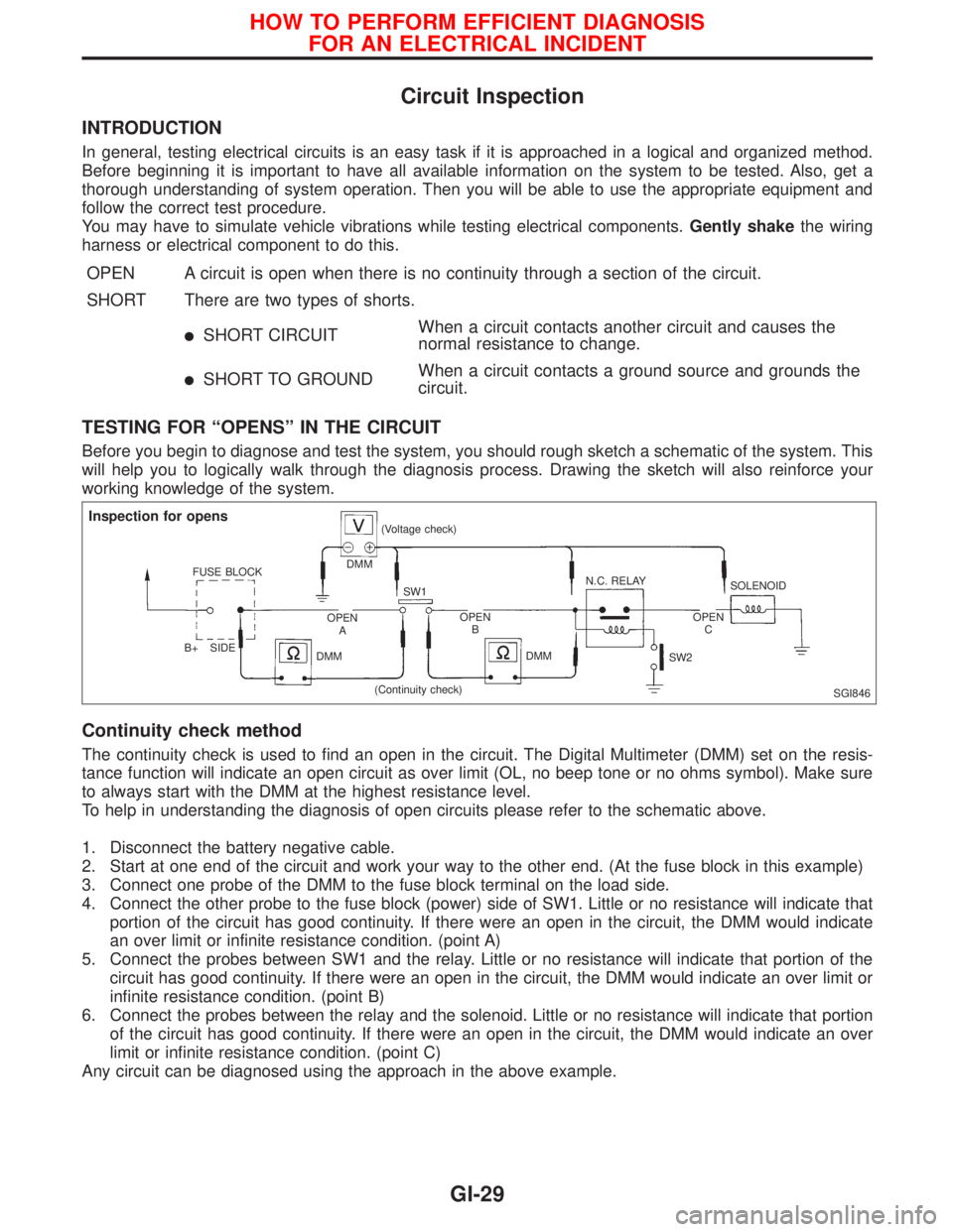
Before you begin to diagnose and test the system, you should rough sketch a schematic of the system. This
will help you to logically walk through the diagnosis process. Drawing the sketch will also reinforce your
working knowledge of the system.
Continuity check method
The continuity check is used to find an open in the circuit. The Digital Multimeter (DMM) set on the resis-
tance function will indicate an open circuit as over limit (OL, no beep tone or no ohms symbol). Make sure
to always start with the DMM at the highest resistance level.
To help in understanding the diagnosis of open circuits please refer to the schematic above.
1. Disconnect the battery negative cable.
2. Start at one end of the circuit and work your way to the other end. (At the fuse block in this example)
3. Connect one probe of the DMM to the fuse block terminal on the load side.
4. Connect the other probe to the fuse block (power) side of SW1. Little or no resistance will indicate that
portion of the circuit has good continuity. If there were an open in the circuit, the DMM would indicate
an over limit or infinite resistance condition. (point A)
5. Connect the probes between SW1 and the relay. Little or no resistance will indicate that portion of the
circuit has good continuity. If there were an open in the circuit, the DMM would indicate an over limit or
infinite resistance condition. (point B)
6. Connect the probes between the relay and the solenoid. Little or no resistance will indicate that portion
of the circuit has good continuity. If there were an open in the circuit, the DMM would indicate an over
limit or infinite resistance condition. (point C)
Any circuit can be diagnosed using the approach in the above example.
SGI846
Inspection for opens
FUSE BLOCK
B+ SIDEDMM(Voltage check)
SW1N.C. RELAY
SOLENOID
OPEN
AOPEN
BOPEN
C
DMMDMM
SW2
(Continuity check)
HOW TO PERFORM EFFICIENT DIAGNOSIS
FOR AN ELECTRICAL INCIDENT
GI-29
Page 1825 of 2267
Voltage check method
To help in understanding the diagnosis of open circuits please refer to the previous schematic.
In any powered circuit, an open can be found by methodically checking the system for the presence of volt-
age. This is done by switching the DMM to the voltage function.
1. Connect one probe of the DMM to a known good ground.
2. Begin probing at one end of the circuit and work your way to the other end.
3. With SW1 open, probe at SW1 to check for voltage.
voltage; open is further down the circuit than SW1.
no voltage; open is between fuse block and SW1 (point A).
4. Close SW1 and probe at relay.
voltage; open is further down the circuit than the relay.
no voltage; open is between SW1 and relay (point B).
5. Close the relay and probe at the solenoid.
voltage; open is further down the circuit than the solenoid.
no voltage; open is between relay and solenoid (point C).
Any powered circuit can be diagnosed using the approach in the above example.
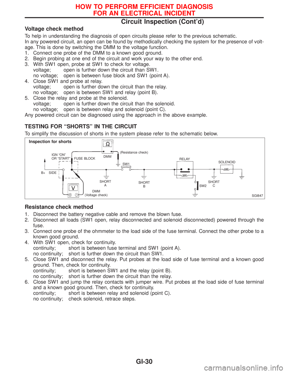
TESTING FOR ªSHORTSº IN THE CIRCUIT
To simplify the discussion of shorts in the system please refer to the schematic below.
Resistance check method
1. Disconnect the battery negative cable and remove the blown fuse.
2. Disconnect all loads (SW1 open, relay disconnected and solenoid disconnected) powered through the
fuse.
3. Connect one probe of the ohmmeter to the load side of the fuse terminal. Connect the other probe to a
known good ground.
4. With SW1 open, check for continuity.
continuity; short is between fuse terminal and SW1 (point A).
no continuity; short is further down the circuit than SW1.
5. Close SW1 and disconnect the relay. Put probes at the load side of fuse terminal and a known good
ground. Then, check for continuity.
continuity; short is between SW1 and the relay (point B).
no continuity; short is further down the circuit than the relay.
6. Close SW1 and jump the relay contacts with jumper wire. Put probes at the load side of fuse terminal
and a known good ground. Then, check for continuity.
continuity; short is between relay and solenoid (point C).
no continuity; check solenoid, retrace steps.
SGI847
Inspection for shorts
IGN ªONº
OR ªSTARTº
B+ SIDEFUSE BLOCKDMM(Resistance check)
SW1RELAY
SOLENOID
SHORT
ASHORT
BSHORT
C
DMM
(Voltage check)SW2
HOW TO PERFORM EFFICIENT DIAGNOSIS
FOR AN ELECTRICAL INCIDENT
Circuit Inspection (Cont'd)
GI-30
Page 1826 of 2267
Voltage check method
1. Remove the blown fuse and disconnect all loads (i.e. SW1 open, relay disconnected and solenoid dis-
connected) powered through the fuse.
2. Turn the ignition key to the ON or START position. Verify battery voltage at the B
+side of the fuse ter-
minal (one lead on the B
+terminal side of the fuse block and one lead on a known good ground).
3. With SW1 open and the DMM leads across both fuse terminals, check for voltage.
voltage; short is between fuse block and SW1 (point A).
no voltage; short is further down the circuit than SW1.
4. With SW1 closed, relay and solenoid disconnected and the DMM leads across both fuse terminals, check
for voltage.
voltage; short is between SW1 and the relay (point B).
no voltage; short is further down the circuit than the relay.
5. With SW1 closed, relay contacts jumped with fused jumper wire check for voltage.
voltage; short is down the circuit of the relay or between the relay and the disconnected solenoid
(point C).
no voltage; retrace steps and check power to fuse block.
GROUND INSPECTION
Ground connections are very important to the proper operation of electrical and electronic circuits. Ground
connections are often exposed to moisture, dirt and other corrosive elements. The corrosion (rust) can
become an unwanted resistance. This unwanted resistance can change the way a circuit works.
Electronically controlled circuits are very sensitive to proper grounding. A loose or corroded ground can
drastically affect an electronically controlled circuit. A poor or corroded ground can easily affect the circuit.
Even when the ground connection looks clean, there can be a thin film of rust on the surface.
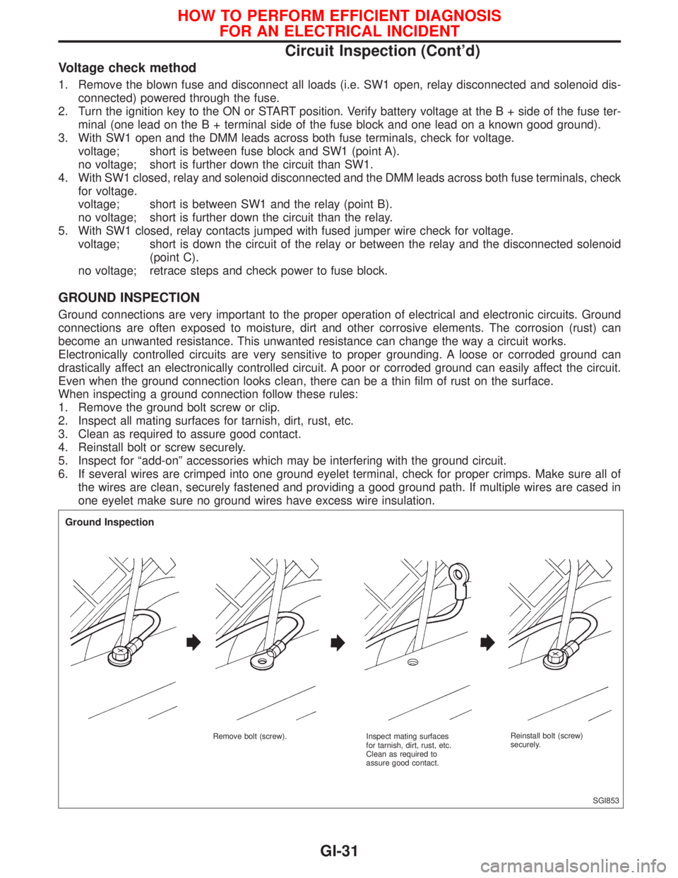
When inspecting a ground connection follow these rules:
1. Remove the ground bolt screw or clip.
2. Inspect all mating surfaces for tarnish, dirt, rust, etc.
3. Clean as required to assure good contact.
4. Reinstall bolt or screw securely.
5. Inspect for ªadd-onº accessories which may be interfering with the ground circuit.
6. If several wires are crimped into one ground eyelet terminal, check for proper crimps. Make sure all of
the wires are clean, securely fastened and providing a good ground path. If multiple wires are cased in
one eyelet make sure no ground wires have excess wire insulation.
SGI853
Ground Inspection
Remove bolt (screw). Inspect mating surfaces
for tarnish, dirt, rust, etc.
Clean as required to
assure good contact.Reinstall bolt (screw)
securely.
HOW TO PERFORM EFFICIENT DIAGNOSIS
FOR AN ELECTRICAL INCIDENT
Circuit Inspection (Cont'd)
GI-31
Page 1827 of 2267
VOLTAGE DROP TESTS
Voltage drop tests are often used to find components or circuits which have excessive resistance. A voltage
drop in a circuit is caused by a resistancewhen the circuit is in operation.
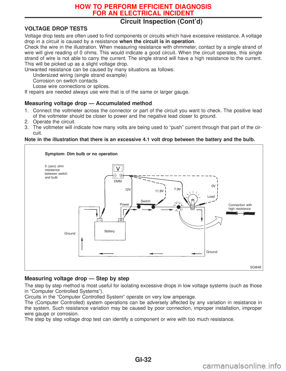
Check the wire in the illustration. When measuring resistance with ohmmeter, contact by a single strand of
wire will give reading of 0 ohms. This would indicate a good circuit. When the circuit operates, this single
strand of wire is not able to carry the current. The single strand will have a high resistance to the current.
This will be picked up as a slight voltage drop.
Unwanted resistance can be caused by many situations as follows:
Undersized wiring (single strand example)
Corrosion on switch contacts
Loose wire connections or splices.
If repairs are needed always use wire that is of the same or larger gauge.
Measuring voltage drop Ð Accumulated method
1. Connect the voltmeter across the connector or part of the circuit you want to check. The positive lead
of the voltmeter should be closer to power and the negative lead closer to ground.
2. Operate the circuit.
3. The voltmeter will indicate how many volts are being used to ªpushº current through that part of the cir-
cuit.
Note in the illustration that there is an excessive 4.1 volt drop between the battery and the bulb.
Measuring voltage drop Ð Step by step
The step by step method is most useful for isolating excessive drops in low voltage systems (such as those
in ªComputer Controlled Systemsº).
Circuits in the ªComputer Controlled Systemº operate on very low amperage.
The (Computer Controlled) system operations can be adversely affected by any variation in resistance in
the system. Such resistance variation may be caused by poor connection, improper installation, improper
wire gauge or corrosion.
The step by step voltage drop test can identify a component or wire with too much resistance.
SGI848
Symptom: Dim bulb or no operation
0 (zero) ohm
resistance
between switch
and bulb
GroundBatteryDMM
PowerSwitchLoad
Connection with
high resistance
Ground
HOW TO PERFORM EFFICIENT DIAGNOSIS
FOR AN ELECTRICAL INCIDENT
Circuit Inspection (Cont'd)
GI-32