Page 1579 of 2267
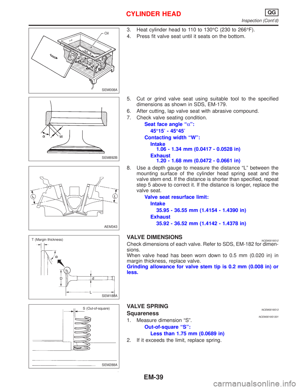
3. Heat cylinder head to 110 to 130ÉC (230 to 266ÉF).
4. Press fit valve seat until it seats on the bottom.
5. Cut or grind valve seat using suitable tool to the specified
dimensions as shown in SDS, EM-179.
6. After cutting, lap valve seat with abrasive compound.
7. Check valve seating condition.
Seat face angle ªaº:
45É15¢- 45É45¢
Contacting width ªWº:
Intake
1.06 - 1.34 mm (0.0417 - 0.0528 in)
Exhaust
1.20 - 1.68 mm (0.0472 - 0.0661 in)
8. Use a depth gauge to measure the distance ªLº between the
mounting surface of the cylinder head spring seat and the
valve stem end. If the distance is shorter than specified, repeat
step 5 above to correct it. If the distance is longer, replace the
valve seat.
Valve seat resurface limit:
Intake
35.95 - 36.55 mm (1.4154 - 1.4390 in)
Exhaust
35.92 - 36.52 mm (1.4142 - 1.4378 in)
VALVE DIMENSIONSNCEM0019S12Check dimensions of each valve. Refer to SDS, EM-182 for dimen-
sions.
When valve head has been worn down to 0.5 mm (0.020 in) in
margin thickness, replace valve.
Grinding allowance for valve stem tip is 0.2 mm (0.008 in) or
less.
VALVE SPRINGNCEM0019S13SquarenessNCEM0019S13011. Measure dimension ªSº.
Out-of-square ªSº:
Less than 1.75 mm (0.0689 in)
2. If it exceeds the limit, replace spring.
SEM008AOil
SEM892B
AEM343
SEM188A T (Margin thickness)
SEM288A S (Out-of-square)
CYLINDER HEADQG
Inspection (Cont'd)
EM-39
Page 1635 of 2267
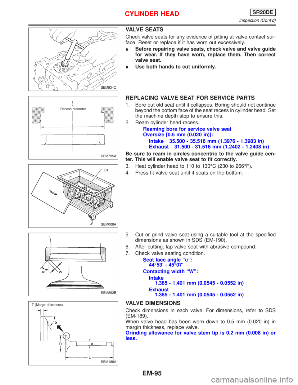
VALVE SEATS
Check valve seats for any evidence of pitting at valve contact sur-
face. Reset or replace if it has worn out excessively.
IBefore repairing valve seats, check valve and valve guide
for wear. If they have worn, replace them. Then correct
valve seat.
IUse both hands to cut uniformly.
REPLACING VALVE SEAT FOR SERVICE PARTS
1. Bore out old seat until it collapses. Boring should not continue
beyond the bottom face of the seat recess in cylinder head. Set
the machine depth stop to ensure this.
2. Ream cylinder head recess.
Reaming bore for service valve seat
Oversize [0.5 mm (0.020 in)]:
Intake 35.500 - 35.516 mm (1.3976 - 1.3983 in)
Exhaust 31.500 - 31.516 mm (1.2402 - 1.2408 in)
Be sure to ream in circles concentric to the valve guide cen-
ter. This will enable valve seat to fit correctly.
3. Heat cylinder head to 110 to 130ÉC (230 to 266ÉF).
4. Press fit valve seat until it seats on the bottom.
5. Cut or grind valve seat using a suitable tool at the specified
dimensions as shown in SDS (EM-190).
6. After cutting, lap valve seat with abrasive compound.
7. Check valve seating condition.
Seat face angle ªaº:
44É53¢- 45É07¢
Contacting width ªWº:
Intake
1.385 - 1.401 mm (0.0545 - 0.0552 in)
Exhaust
1.385 - 1.401 mm (0.0545 - 0.0552 in)
VALVE DIMENSIONS
Check dimensions in each valve. For dimensions, refer to SDS
(EM-189).
When valve head has been worn down to 0.5 mm (0.020 in) in
margin thickness, replace valve.
Grinding allowance for valve stem tip is 0.2 mm (0.008 in) or
less.
SEM934C
SEM795A
.Recess diameter
SEM008AOil
SEM892B
.SEM188A T (Margin thickness)
CYLINDER HEADSR20DE
Inspection (Cont'd)
EM-95
Page 1688 of 2267
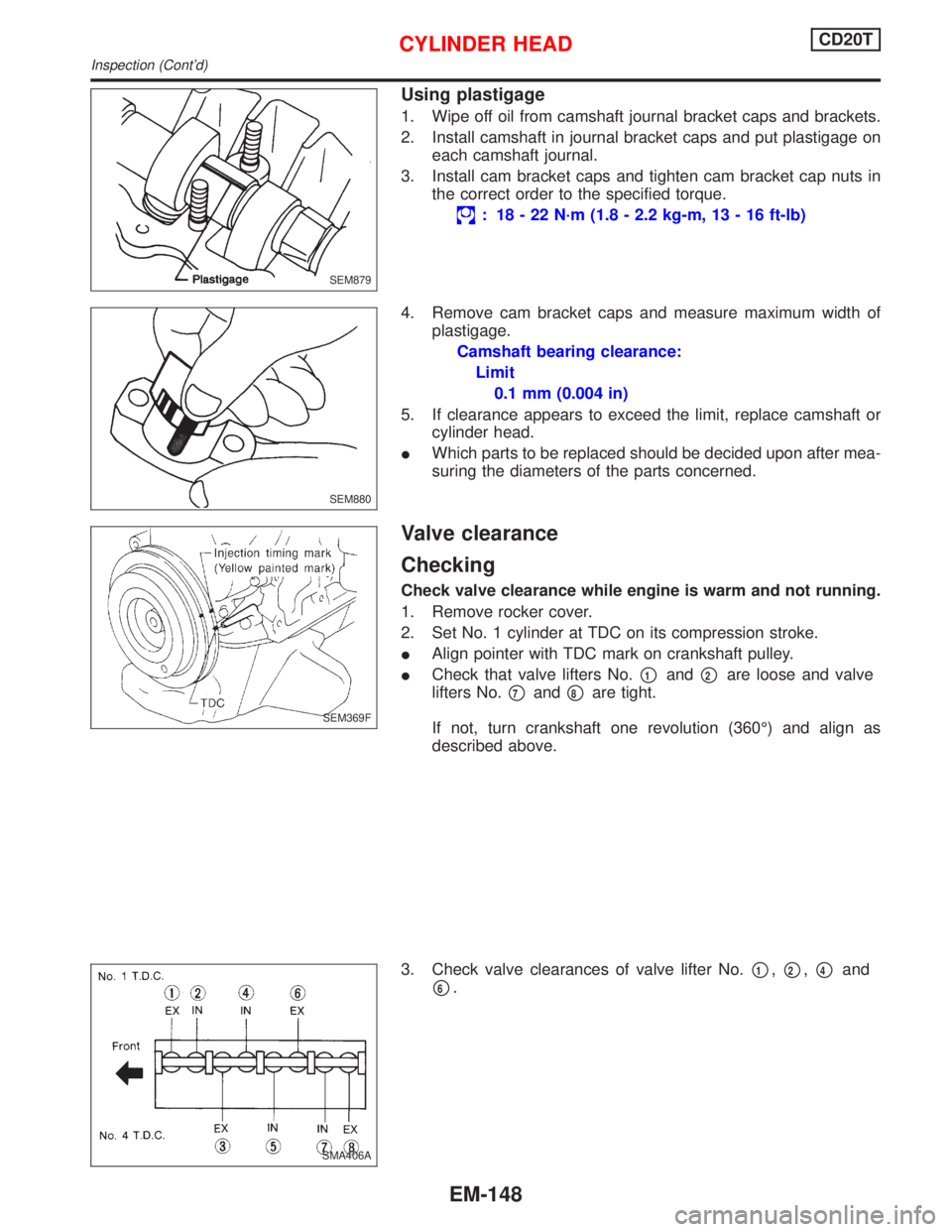
Using plastigage
1. Wipe off oil from camshaft journal bracket caps and brackets.
2. Install camshaft in journal bracket caps and put plastigage on
each camshaft journal.
3. Install cam bracket caps and tighten cam bracket cap nuts in
the correct order to the specified torque.
: 18 - 22 N´m (1.8 - 2.2 kg-m, 13 - 16 ft-lb)
4. Remove cam bracket caps and measure maximum width of
plastigage.
Camshaft bearing clearance:
Limit
0.1 mm (0.004 in)
5. If clearance appears to exceed the limit, replace camshaft or
cylinder head.
IWhich parts to be replaced should be decided upon after mea-
suring the diameters of the parts concerned.
Valve clearance
Checking
Check valve clearance while engine is warm and not running.
1. Remove rocker cover.
2. Set No. 1 cylinder at TDC on its compression stroke.
IAlign pointer with TDC mark on crankshaft pulley.
ICheck that valve lifters No.
p1andp2are loose and valve
lifters No.
p7andp8are tight.
If not, turn crankshaft one revolution (360É) and align as
described above.
3. Check valve clearances of valve lifter No.
p1,p2,p4and
p6.
SEM879
SEM880
SEM369F
SMA406A
CYLINDER HEADCD20T
Inspection (Cont'd)
EM-148
Page 1730 of 2267
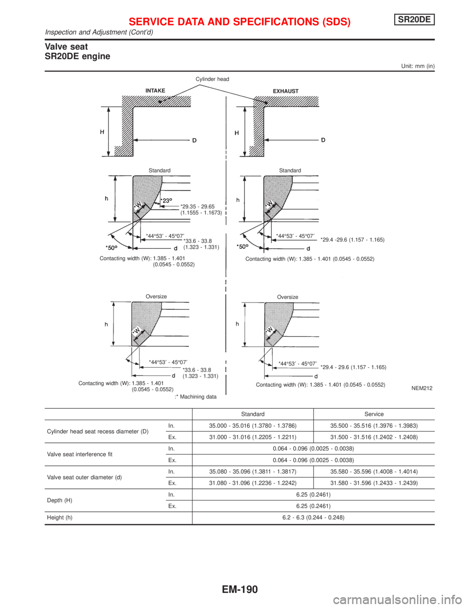
Valve seat
SR20DE engine
Unit: mm (in)
NEM212
Standard Service
Cylinder head seat recess diameter (D)In. 35.000 - 35.016 (1.3780 - 1.3786) 35.500 - 35.516 (1.3976 - 1.3983)
Ex. 31.000 - 31.016 (1.2205 - 1.2211) 31.500 - 31.516 (1.2402 - 1.2408)
Valve seat interference fitIn. 0.064 - 0.096 (0.0025 - 0.0038)
Ex. 0.064 - 0.096 (0.0025 - 0.0038)
Valve seat outer diameter (d)In. 35.080 - 35.096 (1.3811 - 1.3817) 35.580 - 35.596 (1.4008 - 1.4014)
Ex. 31.080 - 31.096 (1.2236 - 1.2242) 31.580 - 31.596 (1.2433 - 1.2439)
Depth (H)In. 6.25 (0.2461)
Ex. 6.25 (0.2461)
Height (h)6.2 - 6.3 (0.244 - 0.248)
INTAKECylinder head
EXHAUST
Standard Standard
*29.35 - 29.65
(1.1555 - 1.1673)
*44É53¢- 45É07¢
*33.6 - 33.8
(1.323 - 1.331)
Contacting width (W): 1.385 - 1.401
(0.0545 - 0.0552)*44É53¢- 45É07¢
*29.4 -29.6 (1.157 - 1.165)
Contacting width (W): 1.385 - 1.401 (0.0545 - 0.0552)
Oversize
Oversize
*44É53¢- 45É07¢
*33.6 - 33.8
(1.323 - 1.331)
Contacting width (W): 1.385 - 1.401
(0.0545 - 0.0552)
:* Machining data*44É53¢- 45É07¢
*29.4 - 29.6 (1.157 - 1.165)
Contacting width (W): 1.385 - 1.401 (0.0545 - 0.0552)
SERVICE DATA AND SPECIFICATIONS (SDS)SR20DE
Inspection and Adjustment (Cont'd)
EM-190
Page 1734 of 2267
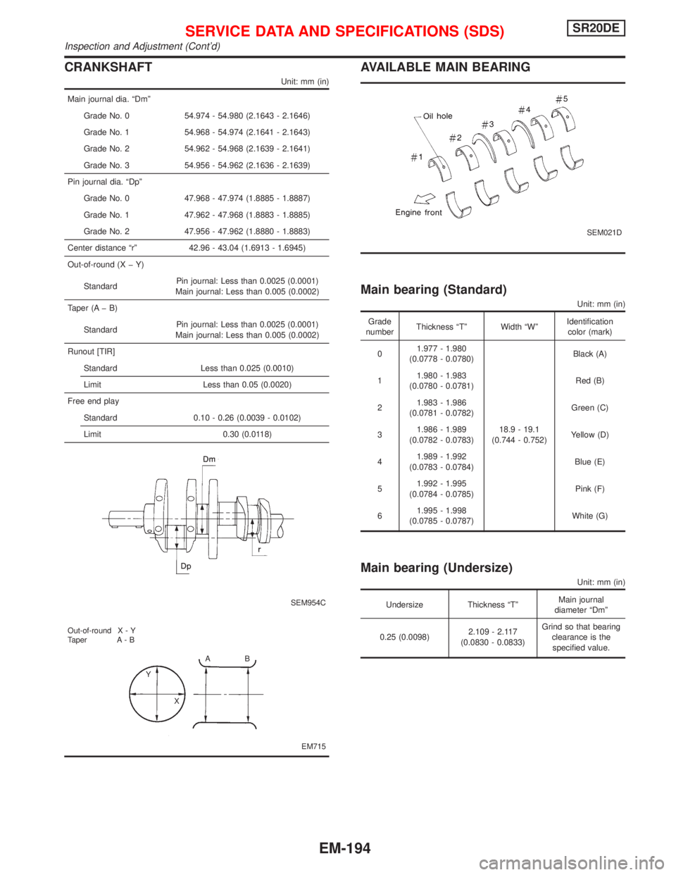
CRANKSHAFT
Unit: mm (in)
Main journal dia. ªDmº
Grade No. 0 54.974 - 54.980 (2.1643 - 2.1646)
Grade No. 1 54.968 - 54.974 (2.1641 - 2.1643)
Grade No. 2 54.962 - 54.968 (2.1639 - 2.1641)
Grade No. 3 54.956 - 54.962 (2.1636 - 2.1639)
Pin journal dia. ªDpº
Grade No. 0 47.968 - 47.974 (1.8885 - 1.8887)
Grade No. 1 47.962 - 47.968 (1.8883 - 1.8885)
Grade No. 2 47.956 - 47.962 (1.8880 - 1.8883)
Center distance ªrº 42.96 - 43.04 (1.6913 - 1.6945)
Out-of-round (X þ Y)
StandardPin journal: Less than 0.0025 (0.0001)
Main journal: Less than 0.005 (0.0002)
Taper (A þ B)
StandardPin journal: Less than 0.0025 (0.0001)
Main journal: Less than 0.005 (0.0002)
Runout [TIR]
Standard Less than 0.025 (0.0010)
Limit Less than 0.05 (0.0020)
Free end play
Standard 0.10 - 0.26 (0.0039 - 0.0102)
Limit 0.30 (0.0118)
SEM954C
EM715 Out-of-round X - Y
Taper A - B
AB
Y
X
AVAILABLE MAIN BEARING
SEM021D
Main bearing (Standard)
Unit: mm (in)
Grade
numberThickness ªTº Width ªWºIdentification
color (mark)
01.977 - 1.980
(0.0778 - 0.0780)
18.9 - 19.1
(0.744 - 0.752)Black (A)
11.980 - 1.983
(0.0780 - 0.0781)Red (B)
21.983 - 1.986
(0.0781 - 0.0782)Green (C)
31.986 - 1.989
(0.0782 - 0.0783)Yellow (D)
41.989 - 1.992
(0.0783 - 0.0784)Blue (E)
51.992 - 1.995
(0.0784 - 0.0785)Pink (F)
61.995 - 1.998
(0.0785 - 0.0787)White (G)
Main bearing (Undersize)
Unit: mm (in)
Undersize Thickness ªTºMain journal
diameter ªDmº
0.25 (0.0098)2.109 - 2.117
(0.0830 - 0.0833)Grind so that bearing
clearance is the
specified value.
SERVICE DATA AND SPECIFICATIONS (SDS)SR20DE
Inspection and Adjustment (Cont'd)
EM-194
Page 1735 of 2267
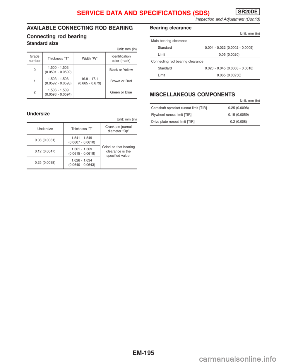
AVAILABLE CONNECTING ROD BEARING
Connecting rod bearing
Standard size
Unit: mm (in)
Grade
numberThickness ªTº Width ªWºIdentification
color (mark)
01.500 - 1.503
(0.0591 - 0.0592)
16.9 - 17.1
(0.665 - 0.673)Black or Yellow
11.503 - 1.506
(0.0592 - 0.0593)Brown or Red
21.506 - 1.509
(0.0593 - 0.0594)Green or Blue
Undersize
Unit: mm (in)
Undersize Thickness ªTºCrank pin journal
diameter ªDpº
0.08 (0.0031)1.541 - 1.549
(0.0607 - 0.0610)
Grind so that bearing
clearance is the
specified value. 0.12 (0.0047)1.561 - 1.569
(0.0615 - 0.0618)
0.25 (0.0098)1.626 - 1.634
(0.0640 - 0.0643)
Bearing clearance
Unit: mm (in)
Main bearing clearance
Standard 0.004 - 0.022 (0.0002 - 0.0009)
Limit 0.05 (0.0020)
Connecting rod bearing clearance
Standard 0.020 - 0.045 (0.0008 - 0.0018)
Limit 0.065 (0.00256)
MISCELLANEOUS COMPONENTS
Unit: mm (in)
Camshaft sprocket runout limit [TIR] 0.25 (0.0098)
Flywheel runout limit [TIR] 0.15 (0.0059)
Drive plate runout limit [TIR] 0.2 (0.008)
SERVICE DATA AND SPECIFICATIONS (SDS)SR20DE
Inspection and Adjustment (Cont'd)
EM-195
Page 1740 of 2267
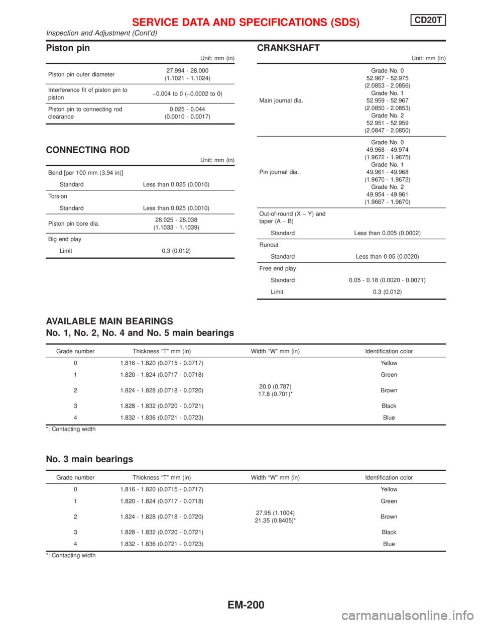
Piston pin
Unit: mm (in)
Piston pin outer diameter27.994 - 28.000
(1.1021 - 1.1024)
Interference fit of piston pin to
pistonþ0.004 to 0 (þ0.0002 to 0)
Piston pin to connecting rod
clearance0.025 - 0.044
(0.0010 - 0.0017)
CONNECTING ROD
Unit: mm (in)
Bend [per 100 mm (3.94 in)]
Standard Less than 0.025 (0.0010)
Torsion
Standard Less than 0.025 (0.0010)
Piston pin bore dia.28.025 - 28.038
(1.1033 - 1.1039)
Big end play
Limit 0.3 (0.012)
CRANKSHAFT
Unit: mm (in)
Main journal dia.Grade No. 0
52.967 - 52.975
(2.0853 - 2.0856)
Grade No. 1
52.959 - 52.967
(2.0850 - 2.0853)
Grade No. 2
52.951 - 52.959
(2.0847 - 2.0850)
Pin journal dia.Grade No. 0
49.968 - 49.974
(1.9672 - 1.9675)
Grade No. 1
49.961 - 49.968
(1.9670 - 1.9672)
Grade No. 2
49.954 - 49.961
(1.9667 - 1.9670)
Out-of-round (X þ Y) and
taper (A þ B)
Standard Less than 0.005 (0.0002)
Runout
Standard Less than 0.05 (0.0020)
Free end play
Standard 0.05 - 0.18 (0.0020 - 0.0071)
Limit 0.3 (0.012)
AVAILABLE MAIN BEARINGS
No. 1, No. 2, No. 4 and No. 5 main bearings
Grade number Thickness ªTº mm (in) Width ªWº mm (in) Identification color
0 1.816 - 1.820 (0.0715 - 0.0717) Yellow
1 1.820 - 1.824 (0.0717 - 0.0718) Green
2 1.824 - 1.828 (0.0718 - 0.0720)20.0 (0.787)
17.8 (0.701)*Brown
3 1.828 - 1.832 (0.0720 - 0.0721) Black
4 1.832 - 1.836 (0.0721 - 0.0723) Blue
*: Contacting width
No. 3 main bearings
Grade number Thickness ªTº mm (in) Width ªWº mm (in) Identification color
0 1.816 - 1.820 (0.0715 - 0.0717) Yellow
1 1.820 - 1.824 (0.0717 - 0.0718) Green
2 1.824 - 1.828 (0.0718 - 0.0720)27.95 (1.1004)
21.35 (0.8405)*Brown
3 1.828 - 1.832 (0.0720 - 0.0721) Black
4 1.832 - 1.836 (0.0721 - 0.0723) Blue
*: Contacting width
SERVICE DATA AND SPECIFICATIONS (SDS)CD20T
Inspection and Adjustment (Cont'd)
EM-200
Page 1840 of 2267
Dimensions
Unit: mm (in)
H/B & Sedan Wagon
Overall length 4522 (178.03) 4566 (179.76)
Overall width 1715 (67.52) *1 1715 (67.52) *1
Overall height 1410 (55.51) *2 1410 (55.51) *2
Front tread 1470 (57.87) 1470 (57.87)
Rear tread 1450 (57.09) 1450 (57.09)
Wheelbase 2600 (102.36) 2600 (102.36)
*1: Without mirrors.
*2: Without roof mounted antenna.
Wheels and Tires
Road
wheelSteel 15 x 6J
ÐÐÐ
Offset
mm (in)45 (1.77)
Aluminum
Ð15x6J 15x6J 16x7J
Offset
mm (in)45 (1.77) 45 (1.77) 45 (1.77)
Tire
sizeConven-
tional185/65HR15 195/60VR15 195/60R15 205/50R16
SpareConven-
tionalConven-
tionalConven-
tional185/65
HR15
IDENTIFICATION INFORMATION
GI-45