Page 1736 of 2267

General Specifications
Cylinder arrangement In-line 4
Displacement cm
3(cu in) 1,974 (120.45)
Bore and stroke mm (in) 84.5´88.0 (3.329´3.465)
Valve arrangement OHC
Firing order 1-3-4-2
Number of piston rings
Compression 2
Oil 1
Number of main bearing 5
Compression ratio 22.2
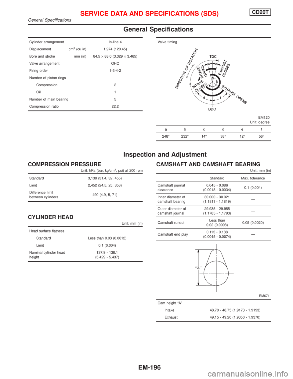
Valve timing
EM120
Unit: degree
abcde f
248É 232É 14É 38É 12É 56É
Inspection and Adjustment
COMPRESSION PRESSURE
Unit: kPa (bar, kg/cm2, psi) at 200 rpm
Standard 3,138 (31.4, 32, 455)
Limit 2,452 (24.5, 25, 356)
Difference limit
between cylinders490 (4.9, 5, 71)
CYLINDER HEAD
Unit: mm (in)
Head surface flatness
Standard Less than 0.03 (0.0012)
Limit 0.1 (0.004)
Nominal cylinder head
height137.9 - 138.1
(5.429 - 5.437)
CAMSHAFT AND CAMSHAFT BEARING
Unit: mm (in)
Standard Max. tolerance
Camshaft journal
clearance0.045 - 0.086
(0.0018 - 0.0034)0.1 (0.004)
Inner diameter of
camshaft bearing30.000 - 30.021
(1.1811 - 1.1819)Ð
Outer diameter of
camshaft journal29.935 - 29.955
(1.1785 - 1.1793)Ð
Camshaft runoutLess than
0.02 (0.0008)0.05 (0.0020)
Camshaft end play0.115 - 0.188
(0.0045 - 0.0074)Ð
EM671
Cam height ªAº
Intake 48.70 - 48.75 (1.9173 - 1.9193)
Exhaust 49.15 - 49.20 (1.9350 - 1.9370)
SERVICE DATA AND SPECIFICATIONS (SDS)CD20T
General Specifications
EM-196
Page 1737 of 2267

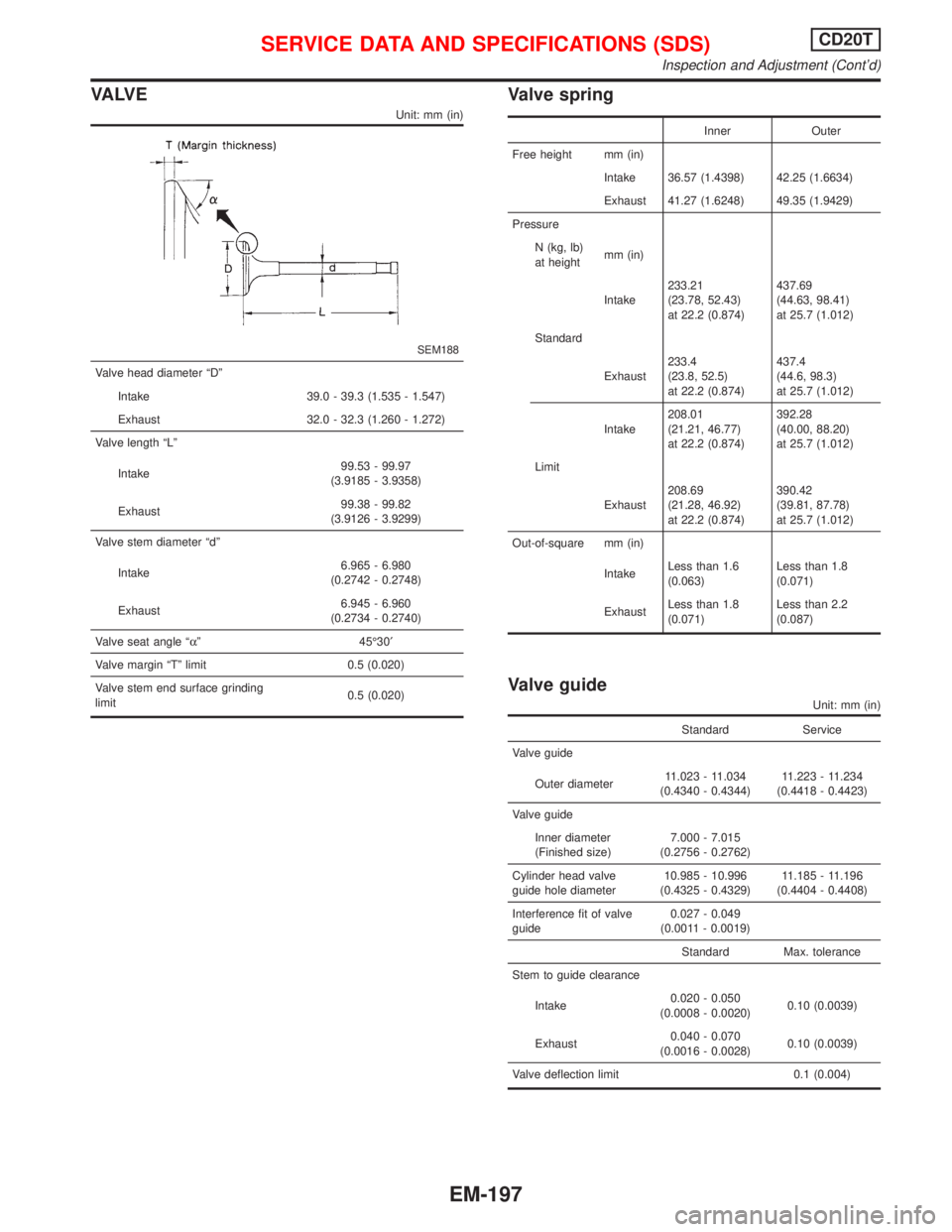
VA LV E
Unit: mm (in)
SEM188
Valve head diameter ªDº
Intake 39.0 - 39.3 (1.535 - 1.547)
Exhaust 32.0 - 32.3 (1.260 - 1.272)
Valve length ªLº
Intake99.53 - 99.97
(3.9185 - 3.9358)
Exhaust99.38 - 99.82
(3.9126 - 3.9299)
Valve stem diameter ªdº
Intake6.965 - 6.980
(0.2742 - 0.2748)
Exhaust6.945 - 6.960
(0.2734 - 0.2740)
Valve seat angle ªaº 45É30¢
Valve margin ªTº limit 0.5 (0.020)
Valve stem end surface grinding
limit0.5 (0.020)
Valve spring
Inner Outer
Free height mm (in)
Intake 36.57 (1.4398) 42.25 (1.6634)
Exhaust 41.27 (1.6248) 49.35 (1.9429)
Pressure
N (kg, lb)
at heightmm (in)
Intake233.21
(23.78, 52.43)
at 22.2 (0.874)437.69
(44.63, 98.41)
at 25.7 (1.012)
Standard
Exhaust233.4
(23.8, 52.5)
at 22.2 (0.874)437.4
(44.6, 98.3)
at 25.7 (1.012)
Intake208.01
(21.21, 46.77)
at 22.2 (0.874)392.28
(40.00, 88.20)
at 25.7 (1.012)
Limit
Exhaust208.69
(21.28, 46.92)
at 22.2 (0.874)390.42
(39.81, 87.78)
at 25.7 (1.012)
Out-of-square mm (in)
IntakeLess than 1.6
(0.063)Less than 1.8
(0.071)
ExhaustLess than 1.8
(0.071)Less than 2.2
(0.087)
Valve guide
Unit: mm (in)
Standard Service
Valve guide
Outer diameter11.023 - 11.034
(0.4340 - 0.4344)11.223 - 11.234
(0.4418 - 0.4423)
Valve guide
Inner diameter
(Finished size)7.000 - 7.015
(0.2756 - 0.2762)
Cylinder head valve
guide hole diameter10.985 - 10.996
(0.4325 - 0.4329)11.185 - 11.196
(0.4404 - 0.4408)
Interference fit of valve
guide0.027 - 0.049
(0.0011 - 0.0019)
Standard Max. tolerance
Stem to guide clearance
Intake0.020 - 0.050
(0.0008 - 0.0020)0.10 (0.0039)
Exhaust0.040 - 0.070
(0.0016 - 0.0028)0.10 (0.0039)
Valve deflection limit 0.1 (0.004)
SERVICE DATA AND SPECIFICATIONS (SDS)CD20T
Inspection and Adjustment (Cont'd)
EM-197
Page 2113 of 2267

ADJUSTMENT OF INPUT SHAFT BRAKING
MECHANISM
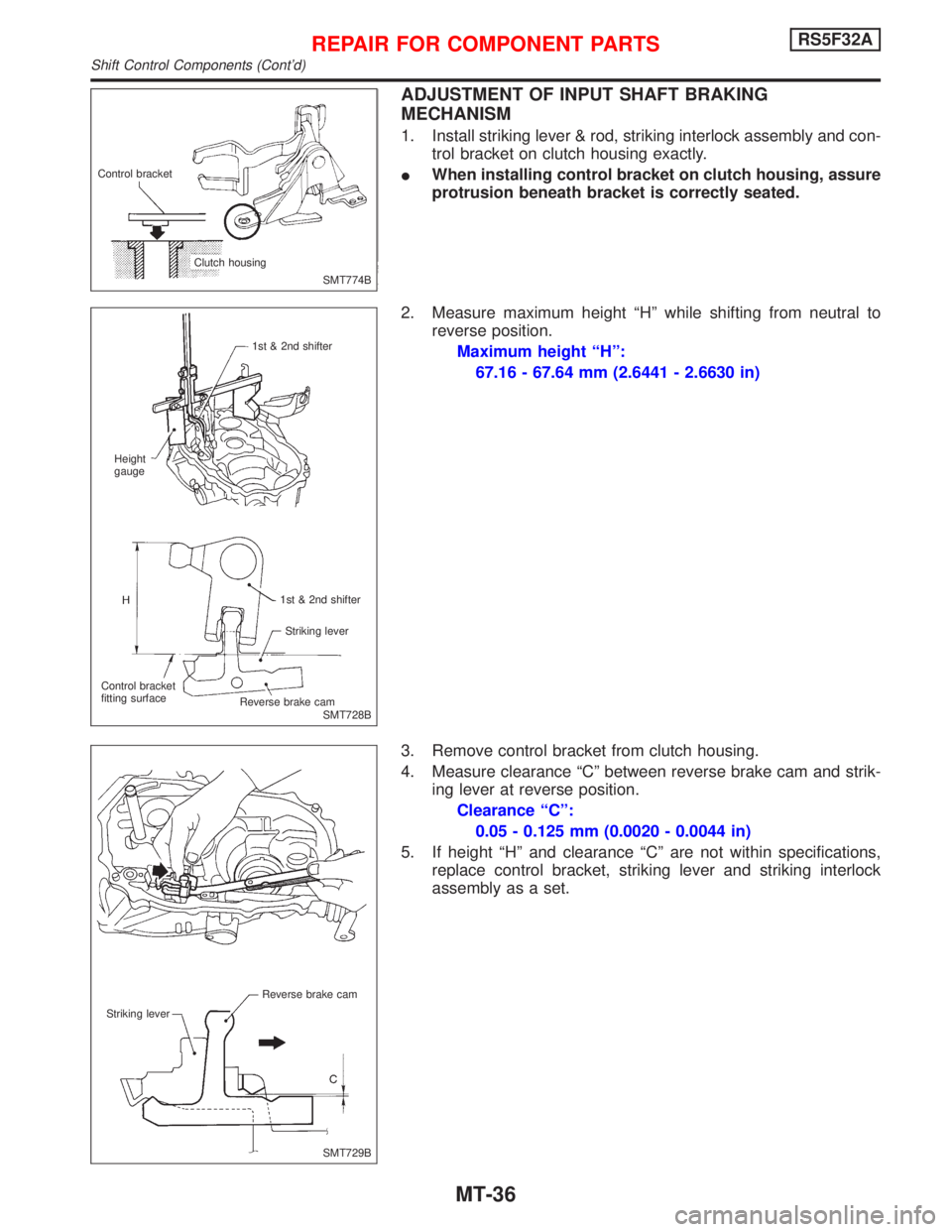
1. Install striking lever & rod, striking interlock assembly and con-
trol bracket on clutch housing exactly.
IWhen installing control bracket on clutch housing, assure
protrusion beneath bracket is correctly seated.
2. Measure maximum height ªHº while shifting from neutral to
reverse position.
Maximum height ªHº:
67.16 - 67.64 mm (2.6441 - 2.6630 in)
3. Remove control bracket from clutch housing.
4. Measure clearance ªCº between reverse brake cam and strik-
ing lever at reverse position.
Clearance ªCº:
0.05 - 0.125 mm (0.0020 - 0.0044 in)
5. If height ªHº and clearance ªCº are not within specifications,
replace control bracket, striking lever and striking interlock
assembly as a set.
SMT774B Control bracket
Clutch housing
SMT728B 1st & 2nd shifter
Height
gauge
1st & 2nd shifter
Striking lever
Control bracket
fitting surface
.Reverse brake cam
SMT729B Reverse brake cam
Striking lever
REPAIR FOR COMPONENT PARTSRS5F32A
Shift Control Components (Cont'd)
MT-36
Page 2166 of 2267
INPUT SHAFT BRAKING MECHANISM
SMT735B 1st & 2nd shifter
Striking lever
Reverse brake cam Control bracket
fitting surface
Maximum height ªHº between the
control bracket fitting surface and
1-2 shifter
mm (in)67.16 - 67.64
(2.6441 - 2.6630)
SMT736B Reverse brake cam
Striking lever
Clearance ªCº between reverse
brake cam and striking lever
mm (in)0.05 - 0.125
(0.0020 - 0.0049)
MAINSHAFT END PLAY
Mainshaft end play
(Clearance between end of case cover and
mainshaft rear bearing outer race)0 - 0.1 mm
(0 - 0.004 in)
Case cover
SMT760B T
Thickness ªTº mm (in) Part No.
10.78 (0.4244) 32131-50J00
10.83 (0.4264) 32131-50J01
10.88 (0.4283) 32131-50J02
10.93 (0.4303) 32131-50J03
10.98 (0.4323) 32131-50J04
11.03 (0.4343) 32131-50J05
SERVICE DATA AND SPECIFICATIONS (SDS)RS5F32A
Inspection and Adjustment Ð RS5F32A (Cont'd)
MT-89
Page:
< prev 1-8 9-16 17-24